

What Is a Custom Extruder Screw and Why Does It Matter
Every polymer behaves differently under heat and shear. So why would you process them all with the same screw? That question sits at the heart of custom extruder screw design - a discipline where geometry, metallurgy, and polymer science converge to solve real production problems.
Defining the Custom Extruder Screw
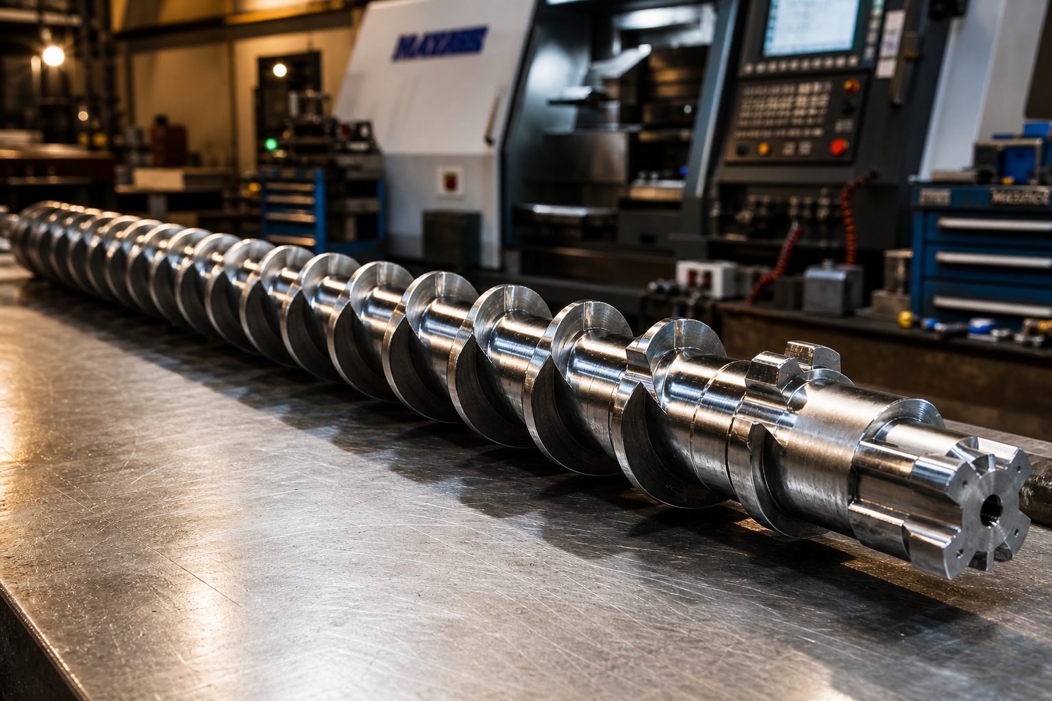
A custom extruder screw is a purpose-engineered screw whose geometry, materials, and functional elements are specifically designed to match a defined polymer, production target, and extruder platform - rather than relying on a generic, one-size-fits-all configuration.
Unlike off-the-shelf replacements, a custom screw is built around your exact process. Its parameters - length-to-diameter (L/D) ratio, compression ratio, channel depths, flight geometry, mixing sections, and surface metallurgy - are all selected to optimize how a specific resin melts, mixes, and flows through your barrel. As extrusion specialist Allan Griff notes, screws can be designed by computer if resistance, output rate, and material viscosities are known, but it is still wise to "season" the computation with real processing experience before cutting metal.
How Custom Screws Differ from Standard Designs
A standard general-purpose extrusion screw typically features a conventional three-zone layout: a deep feed zone, a tapered compression zone, and a shallow metering zone. This works acceptably for a narrow range of commodity resins under moderate conditions. A custom extruder screw, however, modifies each of these zones independently. Imagine processing a glass-filled nylon alongside an unfilled polypropylene on the same extruder line. The feed behavior, melting mechanism, shear sensitivity, and wear profile of these two materials are completely different. A single standard screw geometry simply cannot serve both well.
Key parameters that distinguish a custom design include:
- L/D ratio - matched to the melting and mixing demands of the target resin
- Compression ratio - tuned to the polymer's bulk density and melt behavior
- Flight geometry - optimized for conveying efficiency and shear control
- Barrier flights and mixing elements - added where melt homogeneity or additive dispersion requires it
- Metallurgy and coatings - selected to resist the specific wear or corrosion profile of the material
Who Benefits from Custom Screw Engineering
Plastics engineers running high-output lines, processors handling filled or reinforced compounds, and manufacturers working with heat-sensitive resins like PVC all stand to gain measurable improvements from a properly engineered extruder screw. The same applies to operations experiencing persistent melt quality issues, excessive scrap, or throughput that falls well short of the extruder's rated capacity. Configuring a screw profile is, as NC State Extension research describes, "a blend of art and science" - no gold standard exists because every material exhibits unique flow properties influenced by temperature, shear rate, and extruder geometry.
The sections ahead break down the engineering reasoning behind every major customization decision - from polymer rheology and screw zone design to material-specific geometry recommendations and total cost of ownership. Whether you are diagnosing a current performance gap or evaluating your first custom screw investment, the goal is to give you the technical foundation to make informed choices.
Signs Your Standard Screw Is Underperforming
A general-purpose screw rarely fails dramatically. Instead, it quietly underdelivers - shaving a few percentage points off throughput here, introducing a subtle melt inconsistency there. The trouble is, many processors live with these issues for months or even years, attributing them to material variability or downstream equipment when the root cause sits inside the barrel. Recognizing the warning signs early is the first step toward determining whether your screw extrusion process needs a geometry upgrade.
Common Symptoms of Screw-Polymer Mismatch
When the screw profile does not align with how your polymer actually melts and flows, the process tells you - if you know what to look for. The following checklist covers the most reliable diagnostic indicators that your extruder screws may be fighting the material rather than working with it:
- Unmelts and gels in the extrudate - Solid particles or gel specks appearing in finished product indicate incomplete melting in the transition zone. This often means the compression ratio or channel depth is mismatched to the resin's melting behavior, leaving pockets of unprocessed material that pass through the metering section.
- Output surging or pressure instability - Cyclic fluctuations in die pressure, strand diameter, or part weight point to unstable solids conveying or inconsistent melt formation along the screw. As extrusion research by Mark Spalding documents, flow surging in smooth-bore extruders most commonly originates from improper temperature conditions in the solids conveying section, though it can also stem from melting instabilities when the screw geometry does not match the resin.
- Excessive melt temperature - When the actual melt temperature consistently exceeds the polymer's recommended processing window despite moderate barrel settings, the screw is generating too much shear heating. This typically points to an overly aggressive compression ratio or insufficient channel depth in the metering zone for that particular material.
- Visible thermal degradation - Discoloration, yellowing, black specks, or burnt odor are clear evidence that the polymer is spending too long at elevated temperatures or encountering localized shear hot spots. Streamlined flow paths and properly sized residence time are design decisions, not process adjustments.
- Low throughput relative to extruder capacity - If your line runs well below the extruder's rated output despite stable conditions, the plastic extrusion screw may be limiting solids conveying efficiency or creating a melting bottleneck that restricts how much material can move through the barrel per revolution.
- High scrap or reject rates - Persistent quality failures - whether dimensional variation, poor surface finish, or inconsistent mechanical properties - often trace back to melt non-uniformity that no amount of downstream adjustment can fully correct.
Diagnosing Melt Quality and Output Problems
These symptoms rarely appear in isolation. You might notice surging and elevated melt temperature at the same time, or see gels alongside reduced throughput. That overlap actually helps narrow the diagnosis. For example, unmelts combined with high melt temperature suggest the screw is overworking the already-molten material while failing to fully melt the remaining solids - a classic sign that the compression profile does not match the resin's solid-bed behavior. The majority of melt energy in a single-screw extruder comes from shear heating generated in the compression zone, not from barrel heaters. When channel geometry does not deliver the right shear at the right location, both melt quality and energy efficiency suffer simultaneously.
When to Investigate Custom Screw Solutions
Use the checklist above as a quick self-assessment. If you are experiencing one or two of these symptoms and they correlate with a recent resin change or worn hardware, the fix might be as simple as adjusting process settings or reconditioning the existing screw. However, if multiple symptoms persist across different operating conditions - or if they appeared from day one with a particular polymer - the geometry itself is likely the limiting factor. That is precisely where custom screw engineering delivers its value: by reshaping the feed, compression, and metering zones to match what the polymer actually needs rather than forcing the material through a generic profile.
The logical next question becomes: what exactly about a polymer's behavior dictates these design choices? The answer lies in rheology - the science of how plastics flow, shear, and degrade - and it influences every dimension on a custom screw drawing.
How Polymer Rheology Drives Every Custom Screw Decision
Rheology - the science of how materials flow under stress - is the invisible hand that shapes every dimension on a plastic extruder screw drawing. A screw designer does not choose channel depths, compression ratios, or metering zone lengths arbitrarily. Those decisions flow directly from three measurable polymer properties: melt viscosity, shear sensitivity, and thermal degradation threshold. Ignore any one of them, and the result is a screw that fights the material instead of processing it efficiently.
Viscosity, Shear Sensitivity, and Thermal Limits
Imagine two polyethylene grades with nearly identical melt flow index values. You might assume they behave the same in your extruder. They don't. Computational fluid dynamics (CFD) modeling by Cloeren Incorporated demonstrated this vividly: an LDPE and a metallocene LLDPE with comparable MFI values produced dramatically different results through the same screw mixer. The LDPE generated a pressure drop of roughly 6 MPa and a 4 degrees C temperature rise, while the mLLDPE produced a 19 MPa pressure drop and an 11 degrees C temperature increase - nearly three times the shear heating. The reason? Their shear-thinning behaviors differed substantially. LDPE, with its long-chain branching, shear-thins aggressively, dropping viscosity at high shear rates. The linear mLLDPE maintained much higher viscosity at the same shear rates.
This example exposes a critical screw design principle: melt viscosity at processing shear rates - not just the MFI number on a data sheet - determines how deep to cut channels and how aggressively to compress the melt. A high-viscosity polymer at processing shear rates needs deeper channels and gentler compression to avoid excessive shear heating. A polymer that shear-thins readily can tolerate shallower metering depths and tighter flight clearances without overheating.
Thermal degradation thresholds add another hard constraint. Some polymers, such as PVC, certain nylons, and thermoplastic polyurethanes, are especially vulnerable to time-at-temperature damage. Research at the University of Massachusetts Lowell found that PLA molecular weight decreased linearly with increasing residence time during extrusion - even when melt temperatures remained relatively low. Reducing residence time by increasing feed rates cut molecular weight loss nearly in half. For a screw plastic extruder processing these sensitive materials, the takeaway is clear: compression ratios must stay low enough to avoid excessive shear heating, and channel geometry must minimize how long the melt sits at elevated temperature.
Crystalline vs Amorphous Polymers in Screw Design
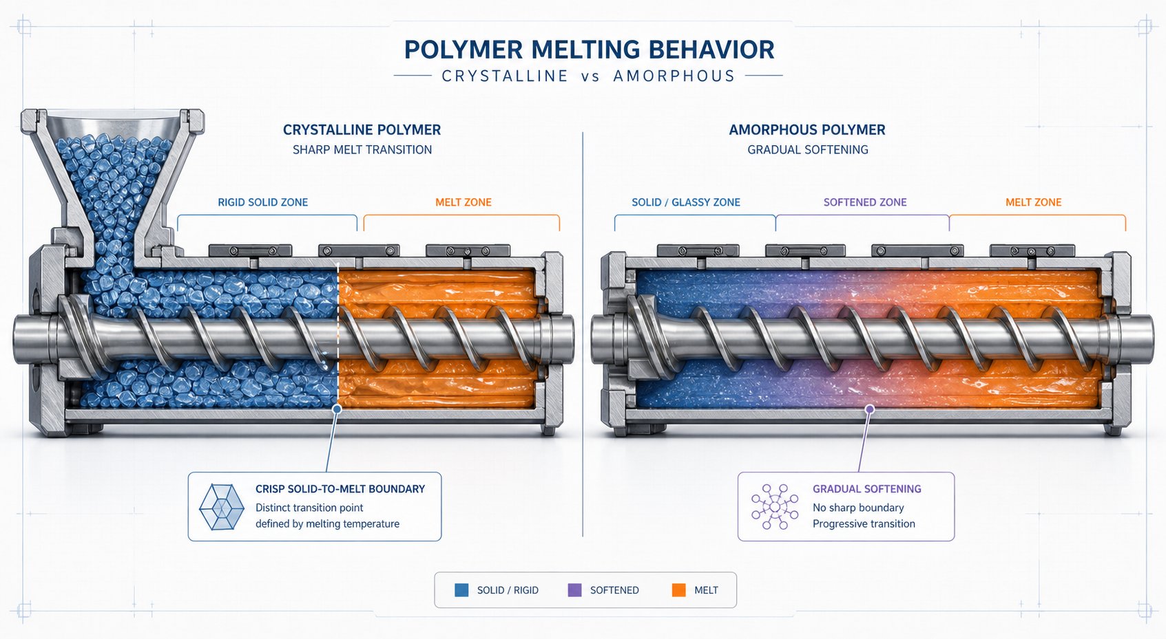
The way a polymer transitions from solid to liquid fundamentally changes what the screw must do in the compression zone. Crystalline polymers like PE, PP, PA, and PET have a defined melting point and absorb a large latent heat of fusion as crystalline structures collapse. This produces a sharp solid-to-melt transition that demands higher compression ratios to accommodate the sudden density change. Amorphous polymers like PS, ABS, and PC soften gradually over a wide temperature range with no latent heat spike. They need gentler, more gradual compression to avoid overworking material that is softening but not yet fully molten.
Industry screw dimension data reinforces this distinction. General-purpose screws for amorphous resins like PS and ABS typically use compression ratios around 2.0 to 2.4 with longer compression sections (roughly 30% of screw length). Crystalline nylons and PBT, by contrast, call for compression ratios near 3.0 with shorter, more abrupt compression zones (around 20% of screw length) because the sharp melting transition allows - and in fact requires - rapid volume reduction.
| Parameter | Crystalline Polymers (PE, PP, PA, PET) | Amorphous Polymers (PS, ABS, PC) |
|---|---|---|
| Melting Mechanism | Sharp melting point with latent heat absorption; defined solid-melt boundary | Gradual softening over a wide temperature range; no distinct melting point |
| Compression Ratio Range | 2.5 - 3.5 (higher ratios to handle sudden density change) | 2.0 - 2.4 (lower ratios for gradual transition) |
| Compression Zone Length | Short (abrupt type, ~20% of screw length) | Long (gradual type, ~30% or more of screw length) |
| Shear Sensitivity | Generally moderate; many crystalline resins tolerate higher shear without rapid degradation | Varies widely; PC and PMMA require careful shear management to prevent degradation and discoloration |
| Recommended Screw Features | Barrier flights to manage distinct solid bed; deeper feed channels for low bulk-density pellets; higher compression for density change at melt | Gradual compression profile; streamlined flow paths to avoid dead spots; moderate metering depths to balance mixing with shear control |
Connecting Rheology to Screw Parameters
Every major screw dimension traces back to one or more of these rheological realities. Channel depth in the metering section is primarily a viscosity decision - deeper for high-viscosity, shear-sensitive polymers, shallower for those that benefit from intensive mixing. Compression ratio is driven by the solid-to-melt transition: sharp and crystalline means aggressive compression, gradual and amorphous means a gentle taper. Residence time constraints from thermal stability data dictate how long the metering zone can be and whether the screw design should incorporate streamlined flow paths versus extended mixing sections.
This is why simply specifying a "general-purpose" screw for a new resin almost always leaves performance on the table. The rheology of every polymer family - and often every grade within a family - encodes specific geometric requirements that only a purpose-built screw can fulfill. Those geometric requirements, however, extend beyond zone depths and ratios into specialized elements like barrier flights, mixing sections, and venting zones that address challenges standard designs were never built to handle.
Anatomy of Custom Screw Geometry and Specialized Elements
A standard three-zone screw treats the feed, compression, and metering sections as a fixed package - change one, and you are stuck with the rest. Custom screw design flips that approach. Each zone is independently engineered around the specific demands of the polymer and the production target. On top of that foundation, specialized elements like barrier flights, mixing sections, and venting zones can be added precisely where the process requires them. Think of it as assembling a purpose-built toolkit rather than grabbing a one-size wrench from the drawer.
Feed, Compression, and Metering Zone Customization
Every screw extruder relies on the same three functional zones, but how a designer shapes each one makes the difference between an average performer and a precisely tuned machine.
The feed zone is where solid pellets enter the barrel channel. Its primary job is conveying - pulling material from the hopper and pushing it forward consistently. Channel depth here directly governs intake volume: deeper channels accept more material per revolution, boosting potential throughput. However, as Far East Network's engineering overview points out, deeper channels also increase the distance between pellets and the heated barrel wall, weakening conductive preheating. A custom design balances these competing demands by adjusting both the channel depth and the feed zone length so that resin arrives at the compression zone adequately preheated - avoiding the residence-time penalties of underheated solids stalling in the transition.
The compression (transition) zone is where melting happens in earnest. The channel depth decreases along its length, squeezing the softening polymer to expel trapped air and generate shear heat. Two compression styles exist: rapid and gradual. Rapid compression produces intense shear heat quickly - ideal for crystalline polymers with sharp melting points. Gradual compression spreads the energy input over a longer section, suiting amorphous resins that soften progressively. A custom screw machining approach selects not just the compression ratio but also the taper profile and zone length to match the polymer's exact melting behavior.
The metering zone maintains a constant, shallow channel depth to deliver homogeneous melt to the die at stable pressure. Channel depth here is largely a viscosity decision. Too shallow, and high-viscosity melts generate excessive shear heating. Too deep, and pressure stability suffers. Custom designs tune metering depth and length to the target throughput and the polymer's viscosity at processing shear rates - variables that a general-purpose screw simply cannot accommodate for every resin.
Barrier Flights and Mixing Element Design
Beyond adjusting the three classical zones, screw designers incorporate specialized functional elements to solve problems that zone geometry alone cannot address. The most impactful of these are barrier flights and mixing sections.
Barrier flights add a secondary flight within the compression zone that physically separates the solid bed from the melt pool. The concept originated with the Maillefer barrier design, patented in 1967 as the first melt-separation device used in an extruder screw. As polymer melts against the barrel wall, the molten material flows over the barrier flight's reduced clearance into a dedicated melt channel, while unmelted solids remain trapped in the solids channel until they too liquefy. The result? No unmelted particles can reach the metering zone. Subsequent designs by Schippers, Barr, and Dray improved on Maillefer's concept by widening the primary melting channel, increasing melting area - and therefore melting capacity - significantly. Computer simulations by R. Dray Mfg. comparing these designs on a 4.5-inch diameter screw processing LDPE demonstrated melting capacity increases from 539 lb/hr (Maillefer) to 697 lb/hr (Schippers/Barr) and 798 lb/hr (Dray), compared to just 482 lb/hr for a conventional non-barrier screw. A screw designer incorporates barrier flights when the application demands high output, complete melt homogeneity, or both - particularly for blown film, thin sheet, and fiber lines where even a single unmelt is unacceptable.
Mixing sections address a different challenge: uniformly dispersing colorants, fillers, or additives throughout the melt. Two fundamentally different mixing types exist, and confusing them is one of the most common specification errors:
- Dispersive mixers (Maddock/LeRoy, blister rings) - Force melt through a narrow gap under high shear, physically breaking down agglomerates such as pigment clumps, gels, or filler clusters. The Maddock (fluted) mixer uses alternating in-flow and out-flow channels separated by a barrier land. Polymer must cross this land to continue downstream, ensuring every particle experiences intense shear. Blister rings work similarly, creating a restrictive clearance the entire melt stream must pass through. Use these when you need to break things apart.
- Distributive mixers (pineapple mixers, pin mixers, Saxton elements) - Repeatedly split, reorient, and recombine the melt stream without imposing high shear. Pineapple mixers use a pattern of intersecting diamond-shaped channels; pin mixers use rows of protruding pins from the screw root. These designs spread additives evenly through the melt rather than pulverizing them. Use these when you need to spread things uniformly, especially with shear-sensitive polymers where a Maddock would cause overheating.
Choosing the wrong type creates problems. A Maddock section on a shear-sensitive TPU can generate destructive localized heating. A pin mixer on a heavily agglomerated pigment concentrate leaves visible color streaks. Experienced screw designers often combine both types in sequence - a dispersive section to break down clumps, followed by a distributive section to spread the broken-down material evenly - tailoring each element's geometry to the material's thermal limits.
Venting Zones and Grooved Feed Sections
Two additional specialized elements address challenges at opposite ends of a screw manufacturing machine's functional range:
- Venting (degassing) zones - In a two-stage screw design, a decompression section midway along the screw drops melt pressure to near zero, allowing moisture, volatiles, and reaction byproducts to escape through a barrel vent port. This is essential for moisture-sensitive polymers like PET (which hydrolyzes if moisture remains), recycled resins carrying absorbed volatiles, and reactive extrusion processes that generate gaseous byproducts. Without proper venting, trapped moisture causes bubbles, splay marks, and molecular weight degradation in the final product. The vent zone depth, length, and location must be carefully engineered to ensure full decompression without allowing melt to flow backward and block the vent - a failure mode called "vent flooding" that defeats the entire purpose.
- Grooved feed sections - Some polymers, particularly HDPE and other polyolefins with high crystallinity and low coefficient of friction, slip against smooth barrel walls in the feed zone rather than being conveyed forward efficiently. Grooved feed sections - longitudinal grooves machined into the barrel's feed throat, not the screw itself - mechanically lock pellets against the barrel surface, dramatically improving solids conveying. The screw designed for a grooved-feed barrel typically features a shallower feed zone and lower compression ratio than its smooth-bore counterpart, because the grooves deliver solids so efficiently that a conventional deep-channel feed section would overfeed the compression zone. This is a prime example of how custom screw geometry must account for the entire extruder system, not just the polymer.
Each of these elements - barrier flights, dispersive and distributive mixers, venting zones, grooved feed sections - exists because a specific processing challenge demanded a geometric solution that the basic three-zone layout could not provide. The engineering reasoning always starts with the same question: what does this particular material need at this particular point in the screw? The answer changes not just by element type but by polymer family, which is precisely why material-specific screw design guidance is the next critical piece of the puzzle.
Material-Specific Screw Design Across Polymer Families
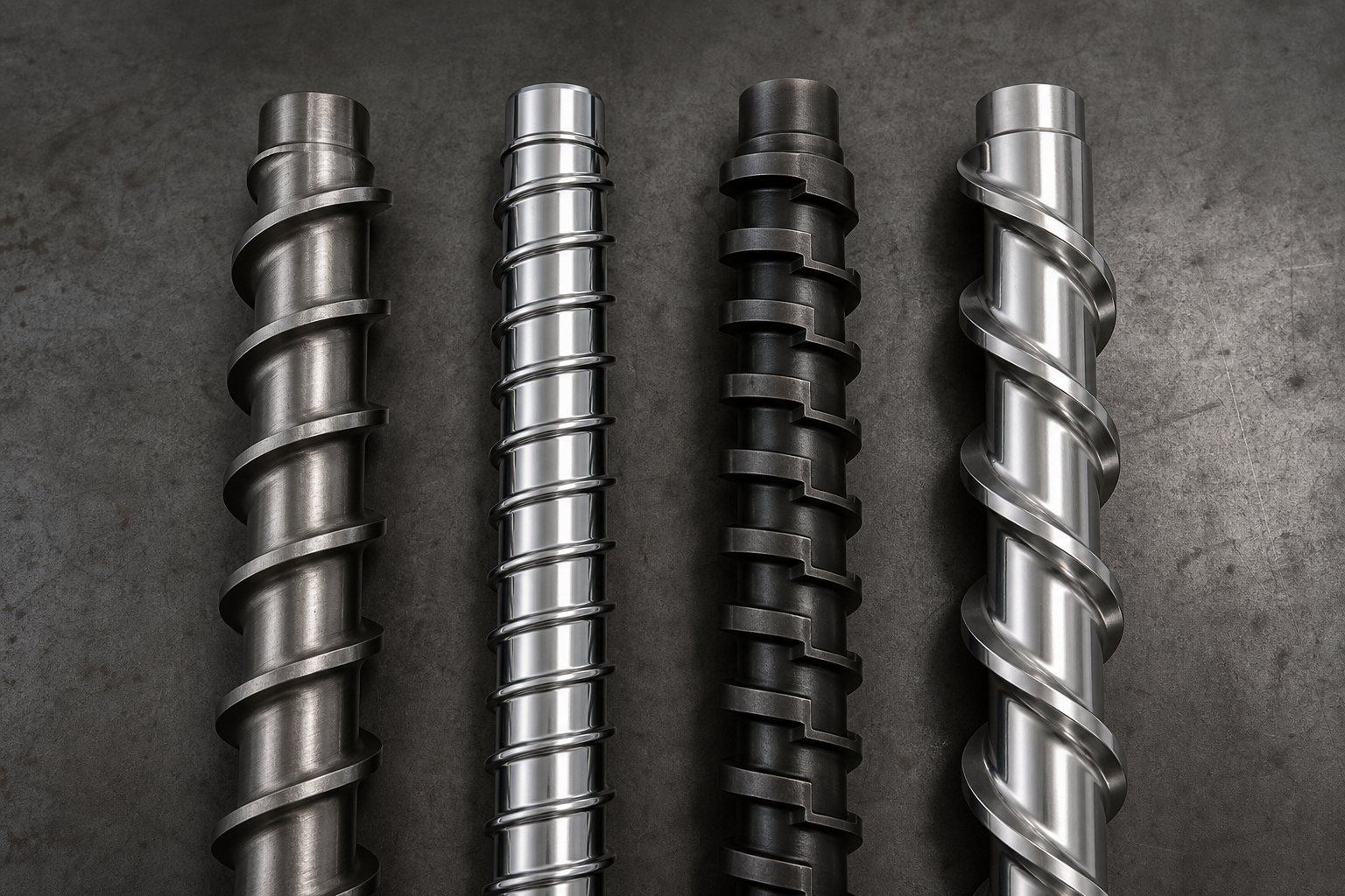
A screw that runs HDPE beautifully can destroy PVC in minutes. A design optimized for rigid nylon may choke on soft TPU pellets before they even reach the compression zone. The geometry, metallurgy, and thermal management strategy for a custom extruder screw must shift - sometimes dramatically - depending on which polymer family you are processing. Yet most industry guidance stops at generic recommendations like "use a lower compression ratio for heat-sensitive materials." That is not nearly specific enough to make real engineering decisions.
Here is where the rubber meets the road - or more accurately, where the polymer meets the flight. Each of the four major polymer families below demands a distinct combination of channel geometry, compression profile, mixing approach, and surface protection. Getting any one of these wrong doesn't just reduce performance; it can introduce scrap, accelerate wear, or actively degrade the material you are trying to process.
Screw Design for Polyolefins and Commodity Resins
Polyolefins - polyethylene (PE) and polypropylene (PP) - are the workhorses of custom extruders worldwide. They are also among the most forgiving resins to process, which is why general-purpose screws often handle them acceptably. But "acceptably" is not "optimally," and high-volume polyolefin processors leave real money on the table with generic geometry.
PE and PP are crystalline polymers with sharp melting points and significant latent heat of fusion. This creates a well-defined solid-melt boundary inside the compression zone - exactly the condition that barrier flight designs were invented to exploit. A custom plastic extruder screw for polyolefins typically features:
- Deep feed channels - Polyolefin pellets have relatively low bulk density, so deeper channels maximize intake volume per screw revolution. Engineering analyses of screw groove depth confirm that a deeper feed section enhances the screw's ability to convey material, though excessive depth can weaken the screw root and impair heat transfer from the barrel wall.
- High compression ratios (3.0 - 4.0) - The sharp crystalline melting transition demands aggressive volume reduction. PE typically calls for ratios of 3.0 to 4.0, while PP sits comfortably in the 2.5 to 4.0 range, depending on the specific grade and form factor.
- Barrier flights - Because the solid bed in a crystalline melt stays intact until it hits the melting point, barrier designs that physically separate solids from melt prevent unmelted particles from reaching the metering zone. This is especially valuable in blown film and thin sheet applications where even a single unmelt creates a visible defect.
- Standard nitrided steel - Unfilled polyolefins are not particularly abrasive or corrosive. A conventional nitrided 4140 or Nitralloy 135M screw provides adequate wear life for most applications, making these among the most cost-effective custom designs to manufacture.
The most common failure mode when running polyolefins on a mismatched screw? Insufficient compression paired with shallow feed channels, leading to poor solids conveying, incomplete melting, and output well below the extruder's rated capacity.
Processing Heat-Sensitive and Corrosive Polymers
PVC is the polymer that keeps screw designers up at night. It degrades rapidly above its relatively narrow processing window, releasing hydrochloric acid gas that corrodes standard barrel and screw steels. PVDC behaves similarly but with even tighter thermal limits. The screw design philosophy here is essentially the opposite of what works for polyolefins - and using the wrong approach is not just a performance problem, it is a safety and equipment longevity issue.
A custom screw for PVC or PVDC prioritizes minimal residence time, gentle shear, and corrosion resistance above all else:
- Low compression ratios (1.8 - 2.5) - Aggressive compression generates excessive shear heat, pushing PVC past its degradation threshold. Screw parameter studies specifically note that thermally sensitive polymers like PVC benefit from shorter L/D ratios and gentler compression, because extended residence time increases the risk of thermal decomposition.
- Shallow, uniform channels - Shallow channel depths reduce the volume of material exposed to heat at any given time, while uniform depth through the metering zone avoids creating shear hot spots where degradation could initiate.
- Streamlined flow paths - Dead spots, sharp transitions, and aggressive mixing elements are strictly avoided. Any location where material can stagnate becomes a degradation site. Screw head geometry is especially critical - a poorly designed tip can trap PVC long enough to produce black specks and contaminate the entire melt stream.
- Corrosion-resistant metallurgy - Standard nitrided steels corrode quickly when exposed to HCl gas released by degrading PVC. Bimetallic barrels lined with nickel-based alloys (such as Hastelloy or Inconel) and screws with hard chrome plating or nickel alloy coatings are standard practice for any serious PVC operation.
Run PVC through a high-compression polyolefin screw, and you will see the consequences within hours: yellowing, black specks, barrel corrosion, and a production line that smells like a chemistry lab gone wrong. The screw production machine that builds PVC screws must hold tight tolerances on channel depth uniformity, because even small variations in depth create localized shear differences that a forgiving resin like PE would never notice but PVC absolutely will.
Engineering Plastics and Filled Compounds
Engineering plastics - polyamides (PA/nylon), PET, PBT, and polycarbonate - occupy a middle ground between the robust processing characteristics of polyolefins and the extreme sensitivity of PVC. They bring their own distinct challenges: crystalline melting behavior (for PA, PET, and PBT), moisture sensitivity, and frequently the addition of glass fibers, mineral fillers, or flame retardants that dramatically change wear dynamics inside the barrel.
Custom screw design for this family focuses on three priorities:
- Moderate compression ratios (2.5 - 3.5) - Crystalline engineering resins need enough compression to accommodate the density change at melt, but not so much that shear heating pushes them beyond their processing windows. PA66, for example, typically calls for a compression ratio around 3.5 to 3.7, while reinforced polyester grades sit near 3.5.
- Barrier screw designs - The sharp crystalline melting transitions in nylon and PET make barrier flights highly effective. Separating the solid bed from the melt pool ensures complete melting before the material enters the metering zone - critical for applications like fiber spinning and precision injection molding where unmelts cause immediate part rejection.
- Wear-resistant tool steels and coatings - This is where metallurgy becomes a make-or-break decision. Unfilled nylon is mildly abrasive at worst. Add 30% glass fiber, and the wear rate on a standard nitrided screw accelerates by an order of magnitude. Glass-filled grades demand D2 or CPM tool steels, tungsten carbide coatings, or bimetallic construction with abrasion-resistant alloy overlays on flight lands. Without proper surface protection, flight diameter wears down rapidly, increasing screw-barrel clearance and causing the very backflow, pressure instability, and melt temperature spikes discussed earlier in this article.
Moisture management also shapes the screw layout. PA and PET are hygroscopic - they absorb atmospheric moisture that causes hydrolytic degradation during processing. While pre-drying is standard practice, many processors add vented (two-stage) screw designs as insurance, incorporating a decompression zone and barrel vent port to extract any residual moisture before the melt reaches the die.
A fourth polymer family - thermoplastic elastomers (TPU, TPE, TPV) - rounds out the material-specific design landscape. These soft, rubbery materials present unique challenges that have nothing to do with melting point or abrasion. TPU pellets are tacky and prone to bridging in the feed throat. TPE compounds can be shear-sensitive enough that conventional metering zones degrade their elastomeric properties. Custom designs for these materials typically use:
- Specially profiled feed sections - Wider, polished channels with undercut flights help prevent sticky pellets from agglomerating and blocking material flow before they even reach the compression zone.
- Low-shear metering geometry - Deeper metering channels and gentler flight clearances reduce viscous dissipation, preserving the elastomeric microstructure that gives these materials their flexibility and recovery properties.
- Distributive mixers only - Dispersive mixing elements like Maddock sections generate too much localized shear for most TPU and TPE compounds. Pineapple or pin-type distributive mixers provide adequate homogenization without the destructive heat buildup.
| Parameter | Polyolefins (PE, PP) | Heat-Sensitive (PVC, PVDC) | Engineering Plastics (PA, PET, PBT) | Thermoplastic Elastomers (TPU, TPE) |
|---|---|---|---|---|
| Compression Ratio Range | 3.0 - 4.0 | 1.8 - 2.5 | 2.5 - 3.7 | 2.0 - 2.8 |
| Channel Depth Strategy | Deep feed for low bulk density; shallow metering for pressure stability | Shallow and uniform throughout; minimize material volume exposed to heat | Moderate feed depth; metering depth tuned to grade viscosity | Wide, polished feed channels to prevent sticking; deeper metering to limit shear |
| Mixing Requirements | Barrier flights for melt separation; dispersive or distributive mixers for color/additive blending | Minimal mixing; avoid aggressive elements that create shear hot spots or dead zones | Barrier flights for crystalline melting; dispersive mixing for glass-fiber dispersion | Distributive only (pineapple or pin type); dispersive elements cause overheating |
| Metallurgy / Coating Needs | Standard nitrided steel (4140 or Nitralloy 135M) sufficient for unfilled grades | Corrosion-resistant bimetallic linings; hard chrome or nickel alloy coatings on screw | Tool steels (D2, CPM) or tungsten carbide coatings for glass-filled grades; nitrided steel for unfilled | Standard nitrided steel; polished surfaces to reduce material adhesion |
| Common Failure Mode with Mismatched Screw | Incomplete melting, low throughput, unmelts in extrudate from insufficient compression | Thermal degradation (yellowing, black specks), HCl corrosion, barrel damage from excessive shear | Rapid flight wear from filled grades; hydrolytic degradation from inadequate moisture removal | Feed bridging from sticky pellets; loss of elastic properties from excessive shear in metering zone |
What stands out across all four families is a consistent theme: the screw must serve the polymer, not the other way around. A single screw geometry simply cannot accommodate the deep-channel, high-compression needs of HDPE and the shallow, gentle, corrosion-resistant requirements of PVC - let alone the sticky-feed, low-shear demands of TPU. This reality is also why the choice between single-screw and twin-screw extruder architectures matters so much. The platform itself constrains which customization strategies are even possible, and that architectural decision often needs to happen before the first screw dimension is ever drawn.
Single-Screw vs Twin-Screw Custom Configurations
Everything discussed so far - zone depths, compression ratios, barrier flights, mixing elements - assumes you have already decided which extruder platform the screw will run in. That decision is not a detail. It is the single most consequential choice in the entire customization process, because the architecture itself determines what kinds of geometric modifications are even possible. A custom screw for a single-screw extruder is a fundamentally different engineering object than a custom screw set for a co-rotating twin, and both differ again from a counter-rotating twin configuration.
Single-Screw Custom Design Considerations
Single-screw extruders dominate profile, pipe, sheet, and film production lines - applications where steady-state output and consistent melt pressure matter more than intense mixing. Customization here focuses on the monolithic screw itself: flight geometry, compression profile, barrier flight placement, channel depths, and the type and location of mixing elements discussed in earlier sections. Every dimension is machined into one continuous piece of steel, and once cut, it is fixed.
This means the design must be right from the start. You cannot rearrange sections after manufacturing the way you can with a modular twin-screw system. The upside? A well-designed single screw delivers excellent conveying efficiency, reliable pressure generation, and lower maintenance costs. A single-screw extruder also relies on friction-driven drag flow to transport material, so flight surface finish, channel geometry, and barrel-wall interaction all become critical variables that a custom design can optimize for a specific resin.
Twin-Screw Co-Rotating vs Counter-Rotating Differences
Twin-screw extruders split into two distinct families, and the customization philosophy differs sharply between them.
Co-rotating twin-screw extruders use two intermeshing screws turning in the same direction. The hallmark of this architecture is modularity - rather than machining a single monolithic screw, engineers assemble individual screw elements (conveying segments, kneading blocks, mixing discs, reverse elements) onto a splined shaft in whatever sequence the application demands. Customization happens through element selection and sequencing, not by redesigning the screw from scratch. Need more dispersive mixing? Add kneading blocks. Need a devolatilization zone? Insert reverse-pitch elements to create a melt seal upstream of the vent port. This flexibility makes co-rotating twins the standard for compounding, reactive extrusion, and multi-component blending where recipes change frequently.
Counter-rotating twin-screw extruders turn the screws in opposite directions, generating strong positive conveying with considerably lower shear. As Technovel's extrusion engineering team explains, the calendering effect at the intermeshing region disperses additives under gentle conditions - critical for thermally sensitive materials like rigid PVC that would degrade under the intense shear of a co-rotating system. Custom designs for counter-rotating twins balance conveying capacity against shear input, often running at high fill and low screw speed to keep material temperature within tight limits. Unlike co-rotating machines, many counter-rotating extruders use partially or fully fixed screw geometries, making the design process closer to single-screw customization in terms of permanence.
Choosing the Right Architecture Before Designing the Screw
Here is the practical takeaway: the architecture decision constrains every screw dimension that follows. You would not design a barrier flight for a co-rotating twin - that concept does not translate to modular element assemblies. You would not specify a Maddock mixer for a counter-rotating PVC extruder - the shear would be destructive. And you would not choose a single-screw platform for a high-filler-loading compounding operation that demands the intense distributive mixing only intermeshing co-rotating screws can deliver.
The table below maps each architecture against its typical applications, customization approach, and key design variables so you can identify which platform aligns with your processing requirements before engaging a screw making machine shop for detailed design work.
| Parameter | Single-Screw | Twin-Screw Co-Rotating | Twin-Screw Counter-Rotating |
|---|---|---|---|
| Typical Applications | Film, sheet, pipe, profile extrusion; pelletizing of single resins | Compounding, reactive extrusion, devolatilization, masterbatch production | PVC pipe and profile, rigid sheet, shear-sensitive formulations |
| Customization Approach | Monolithic screw design: flight geometry, zone depths, barrier flights, and mixing elements machined into a single piece | Modular element selection: conveying, kneading, and mixing segments assembled on a splined shaft in custom sequences | Semi-fixed or fixed screw geometry: compression profile and flight design engineered for low-shear positive conveying |
| Key Design Variables | L/D ratio, compression ratio, channel depth per zone, barrier type, mixer type, metallurgy | Element type and sequence, kneading block stagger angle, screw speed, barrel zone configuration | Compression ratio, flight clearance, screw speed, fill level, calendering gap geometry |
| When Preferred | High-volume continuous extrusion of a single or narrow range of resins; applications demanding steady pressure and output | Multi-component formulations, frequent recipe changes, high-intensity mixing, filled or reactive systems | Heat-sensitive polymers (especially PVC), applications requiring gentle conveying with minimal shear-induced degradation |
Matching your processing goals to the right architecture first, and then customizing screw geometry within that platform, avoids the expensive mistake of optimizing the wrong variable. A beautifully engineered single-screw barrier design cannot compensate for choosing the wrong extruder type in the first place. With the architecture locked in and the screw geometry taking shape, the next decision becomes equally practical: does your application truly require a custom screw, or would a well-chosen general-purpose design deliver acceptable results at lower cost and shorter lead time?
Custom vs General-Purpose Extruder Screws
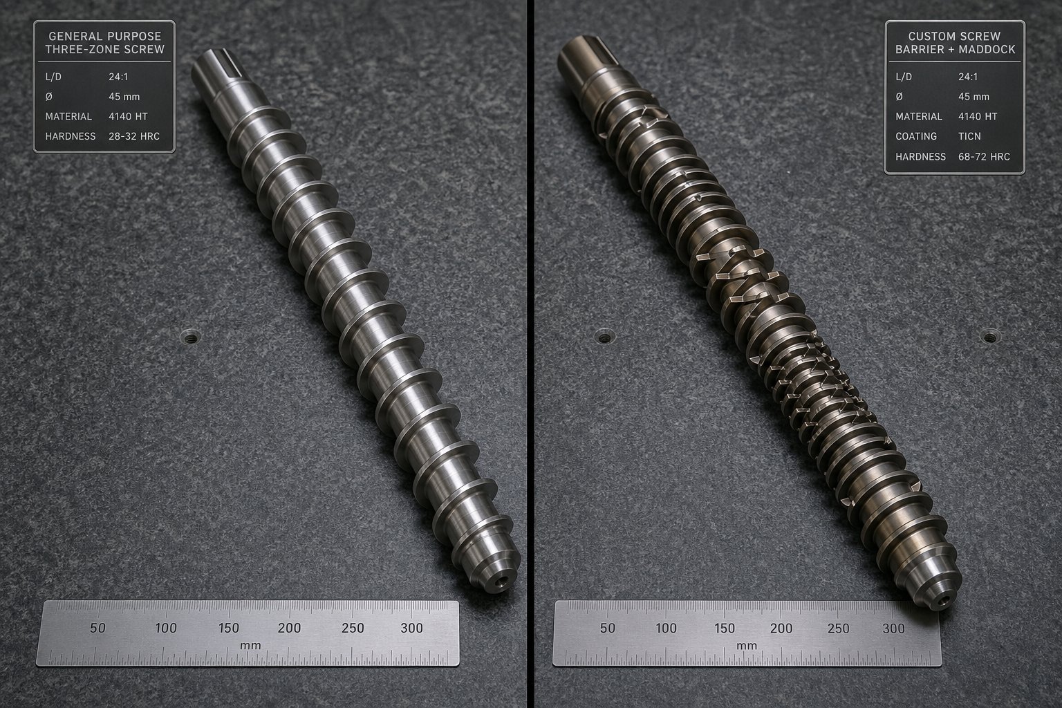
Not every extrusion line needs a custom screw. That might sound counterintuitive in an article devoted to customization, but it is the honest engineering reality - and understanding when a standard design is perfectly adequate saves both money and lead time. The real question is not "custom or standard?" but rather "does my specific combination of polymer, output target, and quality requirement create a gap that only tailored geometry can close?"
When a General-Purpose Screw Is Good Enough
A general-purpose screw earns its name for a reason. Its conventional three-zone layout - deep feed, tapered compression, shallow metering - handles a surprisingly broad range of commodity resins at moderate output levels without major issues. If your operation checks these boxes, a standard design may be all you need:
- Single commodity resin with infrequent changeovers - Running unfilled LDPE, HDPE, or PP on a dedicated line? A general-purpose screw with an appropriate compression ratio for polyolefins will deliver acceptable melt quality for many pipe, profile, and packaging applications.
- Moderate output requirements - If you are not pushing the extruder close to its rated throughput ceiling, the conveying and melting inefficiencies of a generic screw geometry may never become visible bottlenecks. You have headroom to absorb the performance gap.
- Non-critical surface finish or tolerance standards - Products where minor melt temperature variation or the occasional gel does not trigger a customer rejection - think construction-grade profiles, non-optical sheet, or drainage pipe - are forgiving enough that a general-purpose screw's melt homogeneity is sufficient.
- Budget and timeline constraints - Standard replacement screws are often available from stocking programs with minimal lead time. When unplanned downtime demands an immediate replacement, a readily available general-purpose screw gets you running again fast.
In these scenarios, spending extra on custom engineering delivers diminishing returns. The performance difference exists, but it may not justify the investment.
Scenarios That Justify Custom Screw Investment
The calculus shifts decisively when your process introduces variables that a one-size-fits-all geometry simply cannot accommodate. Consider a custom extruder screw when any of the following conditions apply:
- Processing multiple polymers with vastly different rheologies - Switching between crystalline nylon and amorphous ABS on the same extruder means neither resin gets optimal compression, channel depth, or mixing. A custom design can prioritize the higher-volume or more demanding resin, or incorporate compromise geometry that outperforms a generic layout for both.
- Filled or reinforced compounds causing accelerated wear - Glass-fiber-filled engineering plastics, mineral-loaded formulations, and recycled streams containing contaminants chew through standard nitrided flights at alarming rates. Custom metallurgy - tool steels, tungsten carbide overlays, bimetallic construction - matched to the specific abrasion profile extends screw life dramatically and prevents the progressive melt quality degradation that accompanies flight wear.
- High-output or high-quality production targets - Pushing throughput toward the extruder's maximum capacity exposes every melting and conveying limitation in a generic screw. Similarly, applications like optical film, medical tubing, or thin-wall packaging demand melt uniformity that general-purpose designs consistently fail to deliver. Barrier flights, optimized compression profiles, and properly selected mixing elements close these gaps.
- Heat-sensitive resins requiring precise thermal management - PVC, PVDC, certain bioplastics, and thermoplastic elastomers degrade rapidly if residence time or shear heating exceeds narrow limits. As discussed earlier, improper screw selection for heat-sensitive resins leads to degradation, corrosion, and contamination failures that generic geometry actively causes rather than prevents.
- Recurring quality problems traceable to screw performance - If you have already eliminated downstream variables, adjusted process settings within their practical range, and confirmed barrel condition - and the symptoms from our earlier diagnostic checklist persist - the screw geometry itself is the remaining variable. That is the clearest possible justification for a custom solution.
In each of these cases, the question is not whether customization helps but how much production value it unlocks relative to the investment.
Side-by-Side Comparison of Custom vs Standard Screws
The table below lays out the practical differences across the factors that matter most when making this decision. Notice that upfront cost favors the standard screw, but total cost of ownership often tips toward a custom design - especially in high-volume or quality-critical operations where scrap, energy, and maintenance costs accumulate over thousands of production hours.
| Factor | General-Purpose Screw | Custom Extruder Screw |
|---|---|---|
| Upfront Cost | Lower; standard dimensions and materials reduce manufacturing cost | Higher; engineering design time, specialized metallurgy, and precision machining add cost |
| Lead Time | Short; often available from stock or with minimal manufacturing lead time | Longer; requires application review, design engineering, and custom manufacturing (typically 4-10 weeks) |
| Polymer Versatility | Adequate for a narrow range of commodity resins with similar rheology | Optimized for the target polymer or polymer family; may include compromise geometry for planned resin changeovers |
| Output Optimization | Acceptable at moderate throughput; leaves capacity on the table at higher rates | Maximizes conveying and melting efficiency for the specific resin, often recovering 10-20% additional output from the same extruder |
| Melt Quality | Sufficient for non-critical applications; may produce occasional gels, unmelts, or temperature variation | Superior homogeneity from matched compression, barrier flights, and mixing elements; critical for optical, medical, and thin-wall products |
| Maintenance Interval | Shorter if running abrasive or corrosive materials on standard nitrided steel | Extended through material-matched metallurgy; proper coatings and hardened steels reduce flight wear and barrel damage |
| Total Cost of Ownership | Can be higher over time due to increased scrap, lower throughput, energy inefficiency, and more frequent screw replacement | Typically lower over the screw's service life when factoring in scrap reduction, throughput gains, energy savings, and extended wear life |
The honest answer? A general-purpose screw is a perfectly rational choice when conditions are straightforward and the cost of suboptimal performance is low. But the moment your process involves demanding polymers, tight quality specifications, high throughput targets, or recurring melt problems, the economics shift. Custom screws are more expensive upfront but often pay for themselves through reduced scrap, lower energy use, and shorter cycle times - a payback that compounds with every production hour.
Recognizing that your operation falls into the "custom-justified" category is the first step. The natural follow-up is understanding exactly what that investment looks like in dollars - not just the purchase price, but the full economic picture of what a properly engineered screw returns over its service life.
The Economics of Investing in a Custom Extruder Screw
Knowing that a custom screw will outperform a generic one is only half the conversation. The other half - the one most processors actually care about - is whether the performance difference justifies the price tag. Too often, that evaluation starts and ends with a single number: the purchase price of the screw itself. That is like judging a car's value by the sticker price while ignoring fuel economy, maintenance costs, and how many years it runs before needing replacement. A custom extruder screw is a production asset, not a consumable. Evaluating it requires a total cost of ownership framework that accounts for what the screw saves and earns over its full service life - not just what it costs on day one.
What Drives Custom Screw Costs
The price of a custom screw is not arbitrary. It reflects a handful of measurable engineering and manufacturing variables, each of which adds cost for a specific functional reason. Understanding these drivers helps you anticipate pricing and make informed trade-offs during the design phase.
Screw length and diameter set the baseline. A 6-inch diameter, 30:1 L/D screw requires substantially more raw material, more machine time, and tighter tolerance control than a 2.5-inch screw for a lab extruder. Material volume scales roughly with the square of the diameter, so larger screws carry disproportionately higher costs.
Base material and surface treatments represent the single biggest cost variable after size. Standard nitrided alloy steel (such as 38CrMoAlA or 4140) provides a baseline cost. Stepping up to bimetallic construction - where a wear-resistant alloy is centrifugally cast onto the screw's flight surfaces - typically runs 2.0 to 2.5 times the baseline price but extends expected service life from roughly 3,000-5,000 hours to 12,000-15,000 hours. Tungsten carbide coatings push costs to 3.5 to 5.0 times baseline while delivering 25,000+ hours of wear life - a critical investment for glass-filled engineering plastics that would destroy a nitrided screw in weeks. Hard chrome plating falls in the middle at 1.6 to 1.8 times baseline, offering moderate corrosion protection for PVC applications without the full expense of carbide.
Design complexity adds engineering and machining cost. A straightforward three-zone screw with no special elements is the least expensive to manufacture. Barrier flights require precise secondary flight machining with tight clearance control. Mixing elements - Maddock sections, pineapple mixers, blister rings - each add CNC programming, setup changes, and quality verification steps. Two-stage vented designs are longer and demand careful decompression zone profiling. Every functional element discussed in the earlier anatomy section carries a cost premium, but each one exists because a specific processing challenge demanded it.
Lead time for engineering and manufacturing also factors into the economic equation. Custom designs typically require 4 to 10 weeks from initial consultation through delivery, compared to days or a few weeks for a stocked general-purpose replacement. That lead time includes application review, geometry specification, material procurement, heat treatment, precision grinding, and quality verification. Rushed timelines are possible but usually carry expedite surcharges. Planning ahead - ordering before a screw reaches end-of-life rather than after it fails - avoids both the premium and the production downtime.
Measuring ROI Through Production Improvements
Here is where the economics shift decisively in favor of custom designs for processors running demanding applications. The return on investment does not come from the screw being cheaper - it is not. It comes from what the screw does differently once installed. Four measurable categories drive payback:
- Throughput gains from optimized conveying and melting efficiency - A screw whose feed depth, compression profile, and barrier design match the polymer's actual behavior moves more material through the barrel per revolution and melts it more completely. Processors commonly recover 10 to 20 percent additional output from the same extruder hardware simply by replacing a generic screw with one engineered for the specific resin. On a line producing 500 kg/hr, a 15 percent throughput gain translates to 75 additional kilograms every hour - over 600 metric tons of added annual production on a 24/7 schedule. At even modest product margins, that output gain alone can pay for the screw within months.
- Scrap reduction from better melt homogeneity - Unmelts, gels, temperature-induced discoloration, and dimensional inconsistency all generate rejected product. Production data from compounding facility upgrades shows that modern, properly matched screw geometry routinely reduces scrap rates from the 3 to 8 percent range down to 1 to 3 percent. For a line producing one million kilograms annually at a product value of $2.00/kg, cutting scrap from 5 percent to 2 percent saves $60,000 per year in material alone - before accounting for the labor, energy, and machine time wasted producing that scrap in the first place.
- Energy savings from lower required screw speed and back pressure - When screw geometry matches the polymer's rheology, the screw does not have to work as hard to achieve the same output. A higher specific flow rate - more material moved per revolution - allows the extruder to run at a lower RPM while hitting the same throughput target. Flow simulation and lab trial data from Maillefer documented energy savings of 5 to 12 percent on blown fiber microduct lines simply by selecting screws with optimized specific flow characteristics. Lower screw speed also means reduced shear heating, which in turn reduces barrel cooling demand - a secondary energy saving that compounds with the primary motor load reduction.
- Extended maintenance intervals from proper metallurgical selection - Matching the screw's surface treatment to the wear profile of the processed material extends time between replacements dramatically. A standard nitrided screw running glass-filled nylon might last 3,000 to 5,000 hours before flight wear degrades melt quality to unacceptable levels. A tungsten carbide-coated screw in the same application can run 25,000+ hours. That is five to eight times fewer replacements, five to eight times fewer unplanned shutdowns for screw changes, and five to eight times fewer periods of degraded output quality as the old screw wore down in its final hours. The maintenance math alone often justifies the metallurgical upgrade.
The critical mindset shift is this: stop comparing the purchase price of a custom screw to the purchase price of a standard replacement. Instead, compare the custom screw's total cost - including engineering, manufacturing, and installation - to the ongoing costs of not having it: the scrap you keep producing, the throughput you keep leaving on the table, the energy you keep wasting at higher-than-necessary screw speeds, and the replacement screws you keep buying every few thousand hours. When framed this way, the payback period for a well-specified custom design in a demanding application typically falls within 6 to 18 months.
Building a Performance Baseline for Comparison
You cannot measure ROI without a starting point. Before ordering a custom screw, document your current process performance so you have hard numbers to compare against after installation. Sounds obvious, but many processors skip this step and then struggle to quantify the improvement they are seeing - making it harder to justify future investments.
At minimum, record the following over a representative production period (ideally two to four weeks of steady-state operation with your current screw):
- Actual throughput - kilograms per hour at your normal operating screw speed and temperature profile, not the theoretical maximum
- Screw speed (RPM) - the speed required to achieve that throughput, which reveals how hard the screw is working
- Melt temperature - measured at the die, not the barrel set point, to capture shear-induced heating
- Die pressure and pressure stability - average head pressure and the magnitude of any cyclic fluctuations
- Motor load (amps or kW) - the actual energy the drive is consuming, which directly reflects the screw's mechanical efficiency
- Scrap and reject rate - percentage of total output that fails quality inspection, categorized by defect type (gels, unmelts, dimensional, discoloration)
- Screw condition - current flight diameter measurements and estimated hours of service, so you know whether you are baselining against a new or worn screw
With this data in hand, you have a quantifiable before-and-after comparison framework. After the custom screw is installed and the process stabilizes - typically one to two weeks of optimization - run the same measurements under equivalent conditions. The differences in throughput, energy consumption, melt temperature, and scrap rate translate directly into dollars, giving you a concrete ROI number rather than a subjective impression that things "seem better."
This data also serves a second purpose: it gives your screw manufacturer the operational context needed to design the right geometry in the first place. The more precisely you can describe what is happening inside your barrel today, the more precisely an engineer can target the geometric changes that will fix it. Which raises the final practical question - what exactly does the process of specifying, ordering, and commissioning a custom screw look like from the processor's side of the conversation?
How to Specify and Order a Custom Extruder Screw
You have identified the symptoms, understood the rheology, evaluated the architecture, and built a performance baseline. The engineering reasoning is clear: your process needs a custom solution. So what happens next? The gap between deciding you need a custom extruder screw and actually receiving one that performs as expected is bridged by a structured specification and ordering process - one where the quality of information you provide directly determines the quality of the screw you get back.
Information Your Screw Manufacturer Needs from You
Think of this step as giving your screw machine manufacturer the diagnostic data a doctor needs before writing a prescription. Vague descriptions produce vague designs. Precise inputs produce precisely engineered solutions. Before reaching out for a quote, gather the following:
- Extruder make, model, and barrel specifications - This includes barrel bore diameter, L/D ratio, barrel liner material and condition, drive motor size, and maximum RPM. If the barrel has been rebored or relined, note the current ID.
- Primary resin(s) and additives - Specify the exact grade designations, not just generic names. "Nylon 6" is not specific enough - the difference between an unfilled nylon 6 and a 33% glass-filled nylon 66 changes every screw parameter. Include colorants, flame retardants, mineral fillers, and their loading percentages.
- Current and target output rates - What are you producing today in kilograms per hour, and what does the production plan demand? This gap defines how aggressively the new geometry needs to push conveying and melting efficiency.
- Existing problems or performance gaps - Reference the diagnostic checklist from earlier: surging, unmelts, excessive melt temperature, degradation, scrap rates. Quantify wherever possible. "We see gels" is helpful; "we reject 4.2% of output due to gel contamination at 220 RPM" is far more actionable.
- Barrel wear and screw service history - A new screw installed into a worn barrel will not perform to spec. Precision machining experts emphasize that the radial clearance between screw flight OD and barrel ID is the single most critical dimensional relationship in the extruder. Clearance exceeding 0.40 mm on a 65 mm barrel causes severe leakage flow - output drops, melt degrades, and no amount of screw optimization can compensate for a barrel that leaks pressure backward over the flights. Document current barrel bore measurements so the manufacturer can design the screw to match actual barrel condition or recommend barrel reconditioning first.
The Custom Screw Design and Manufacturing Workflow
With your application data assembled, the process follows a logical sequence. Each step builds on the previous one, and skipping stages - especially the front-end engineering - is where costly mistakes originate.
- Initial consultation and application review - A qualified manufacturer reviews your extruder specifications, resin data, production targets, and current pain points. This is not a formality. It is where the engineer identifies which screw parameters need to change and which constraints (barrel geometry, drive capacity, die head requirements) the design must respect.
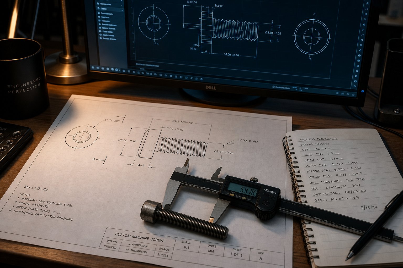
- Screw design proposal with geometry specifications - The manufacturer produces a detailed engineering drawing specifying zone lengths, channel depths, compression ratio, flight pitch and width, barrier flight clearances, mixing element type and placement, and overall L/D. You should receive a CAD drawing with explicit tolerances - not a verbal description or a rough sketch.
- Material and coating selection - Based on the resin's wear and corrosion profile, the engineer recommends base steel, surface treatment, and any coatings. This is where the metallurgy discussions from earlier chapters become purchase decisions: nitrided alloy steel for unfilled commodity resins, bimetallic overlays for abrasive compounds, corrosion-resistant alloys for PVC.
- Manufacturing and quality verification - Precision CNC machining, heat treatment, surface finishing, and dimensional inspection. Demand material test reports (MTRs) and surface treatment verification - a nitriding depth gradient report, not just a surface hardness spot check. Reputable manufacturers provide full documentation traceable to the specific screw you ordered.
- Post-installation performance validation - After installation, run the same baseline measurements you documented before ordering: throughput, melt temperature, die pressure stability, motor load, and scrap rate. Compare the results directly. A well-designed custom screw should show measurable improvement within the first one to two weeks of production once operating parameters are dialed in.
Choosing a Manufacturer with Application Engineering Support
This is where the selection process separates commodity screw suppliers from genuine engineering partners. Any machine shop with CNC lathes and grinders can cut metal to a print. The critical differentiator is whether the manufacturer can help you create the right print in the first place.
Look for these capabilities when evaluating a screw machine manufacturer:
- Application-specific engineering support - The manufacturer should ask detailed questions about your polymer, your process, and your problems before ever quoting a price. If the first response to your inquiry is "send us the dimensions of your old screw," you are dealing with a copy shop, not a design partner.
- Material expertise for specialized polymers - Processing commodity polyolefins is straightforward. Engineering plastics, filled compounds, thermoplastic elastomers, and heat-sensitive resins like PVC each demand different screw geometry and metallurgy choices that require real application knowledge. Your manufacturer should be able to explain why they are recommending a specific compression ratio or coating - not just tell you what it is.
- Tailored geometry for demanding production materials - The ability to design and manufacture barrier flights, application-matched mixing elements, vented two-stage configurations, and specialized feed geometries - not just standard three-zone screws in different sizes.
Manufacturers like NANHAIYA exemplify this consultative approach, offering custom screw design services built around application-driven engineering rather than simple dimension replication. Their focus on processors working with specialized polymers and engineering plastics - materials that demand tailored screw geometry and careful material selection - reflects the kind of partnership that separates a successful custom screw project from an expensive trial-and-error exercise.
Ultimately, the screw is only as good as the conversation that produced it. The processors who get the best results are the ones who treat their screw manufacturer as a collaborative engineering resource - sharing complete application data, asking questions about design rationale, and measuring results rigorously after installation. A custom extruder screw is not a catalog purchase. It is a jointly engineered solution, and the quality of the outcome depends on the quality of the collaboration that shapes it.
Frequently Asked Questions About Custom Extruder Screws
1. How much does a custom extruder screw cost compared to a standard screw?
A custom extruder screw typically costs more upfront due to engineering design time, specialized metallurgy, and precision machining. Surface treatments heavily influence pricing: bimetallic construction runs roughly 2.0 to 2.5 times the baseline nitrided steel cost, while tungsten carbide coatings can reach 3.5 to 5.0 times baseline. However, the total cost of ownership often favors custom designs in demanding applications because they reduce scrap rates, increase throughput by 10-20%, extend maintenance intervals significantly, and lower energy consumption - frequently delivering full payback within 6 to 18 months.
2. What is the difference between a barrier screw and a general-purpose extruder screw?
A general-purpose extruder screw uses a simple three-zone layout (feed, compression, metering) with a single flight. A barrier screw adds a secondary flight in the compression zone that physically separates the unmelted solid bed from the molten polymer pool. This prevents unmelted particles from reaching the metering zone, resulting in superior melt homogeneity and higher melting capacity. Barrier designs are especially effective for crystalline polymers like PE, PP, and nylon, and are commonly specified for blown film, thin sheet, and fiber extrusion where even a single unmelt creates a visible defect.
3. How do I know if my extruder screw needs to be replaced with a custom design?
Key warning signs include persistent unmelts or gels in the extrudate, cyclic output surging or die pressure instability, melt temperatures consistently exceeding the polymer's recommended processing window, visible thermal degradation such as discoloration or black specks, throughput significantly below the extruder's rated capacity, and high scrap or reject rates. If multiple symptoms persist across different operating conditions - especially after ruling out downstream equipment issues and confirming barrel condition - the screw geometry itself is likely the limiting factor and a custom solution should be evaluated.
4. What information does a screw manufacturer need to design a custom extruder screw?
Manufacturers need your extruder make, model, and barrel specifications (bore diameter, L/D ratio, liner condition, drive size); exact resin grade designations and additive loading percentages; current and target output rates in kg/hr; documented performance problems with quantified data where possible; and barrel wear measurements showing current bore dimensions. Providing precise operational data - rather than vague descriptions - directly determines how accurately the engineer can target the geometric changes your process needs. Specialists like NANHAIYA (nhyscrew.com) offer consultative design services that use this application data to engineer screw geometry matched to your specific polymer and production requirements.
5. Can one custom screw work for multiple different polymers?
A single custom screw can be designed with compromise geometry that outperforms a generic layout for a planned set of resins, but it cannot perfectly optimize for polymers with vastly different rheological properties. For example, crystalline nylon and amorphous ABS require different compression ratios, channel depths, and mixing strategies. A custom design can prioritize the higher-volume or more demanding resin while incorporating features that provide acceptable performance for secondary materials. For operations requiring frequent changeovers between very different polymer families, a modular twin-screw co-rotating platform - where element sequences can be rearranged - may be a more practical solution than a monolithic single-screw design.
Written by
Nanhaiya Technical Team
Zhoushan Nanhaiya Plastic Machinery Co., Ltd.
The Nanhaiya technical team supports screw and barrel manufacturing projects through application review, technical communication, custom manufacturing coordination, and production and quality control.
Discuss Your Application
Related Articles
More insights on screw barrel technology and plastics processing.

What Nobody Tells You About Screw Barrel For Plastic Machine Design
Oct 10, 2026
Learn how screw barrel for plastic machine design affects melt quality, throughput, and wear life. Covers geometry, resin matching, troubleshooting, and sourcing.
Read Article
Single Screw Extruder for Sheet: Stop Guessing, Start Specifying
Oct 9, 2026
Learn how to specify a single screw extruder for sheet production. Covers screw geometry, resin-specific processing, troubleshooting, and maintenance best practices.
Read Article
PE Pipe Extruder Machine: What Datasheets Won't Tell You
Oct 9, 2026
Learn how a PE pipe extruder machine works, key specs explained, material grade selection, maintenance tips, and buyer guidance beyond the datasheet.
Read ArticleLooking for something else?
Search by material, symptom or product and jump straight to the relevant page.
These are navigation suggestions based on keyword matching — not a quotation, not a delivery commitment, and not a substitute for engineering review. Final specification is confirmed by our engineers against your drawings and processed material.
Need help with screw barrel selection?
Share your machine model, processed material and application. Our team can help with pricing and technical support.