

What Is a Counter Rotating Twin Screw Extruder
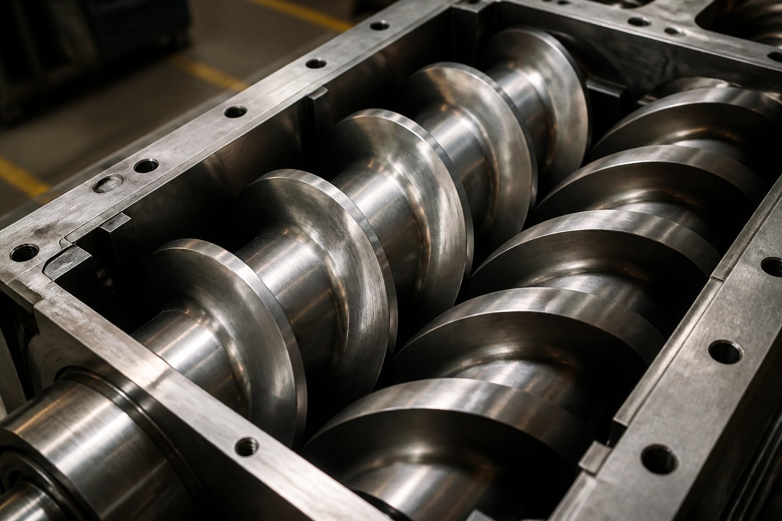
Imagine two screws sitting side by side inside a heated barrel, each one spinning in the opposite direction from its neighbor. One turns clockwise. The other turns counterclockwise. Between them, pockets of polymer are trapped, sealed, and steadily pushed forward. That is the core idea behind a counter rotating twin screw extruder, and it is a concept that most technical resources gloss over far too quickly.
A counter rotating twin screw extruder is a polymer processing machine that uses two intermeshing screws rotating in opposite directions within a shared barrel. The opposing rotation creates enclosed C-shaped chambers between the screw flights and barrel wall, conveying material forward through positive displacement rather than frictional drag.
This distinction, positive displacement versus drag flow, is what separates counter-rotating machines from both single-screw extruders and their co-rotating twin screw extruder counterparts. A single-screw extruder relies almost entirely on friction between the polymer and the barrel wall to move material forward. A co-rotating twin-screw extruder uses two screws turning the same direction, generating intense shear and aggressive mixing. The counter-rotating design sits in a fundamentally different category: it prioritizes controlled, gentle, and predictable material transport.
Defining the Counter Rotating Twin Screw Extruder
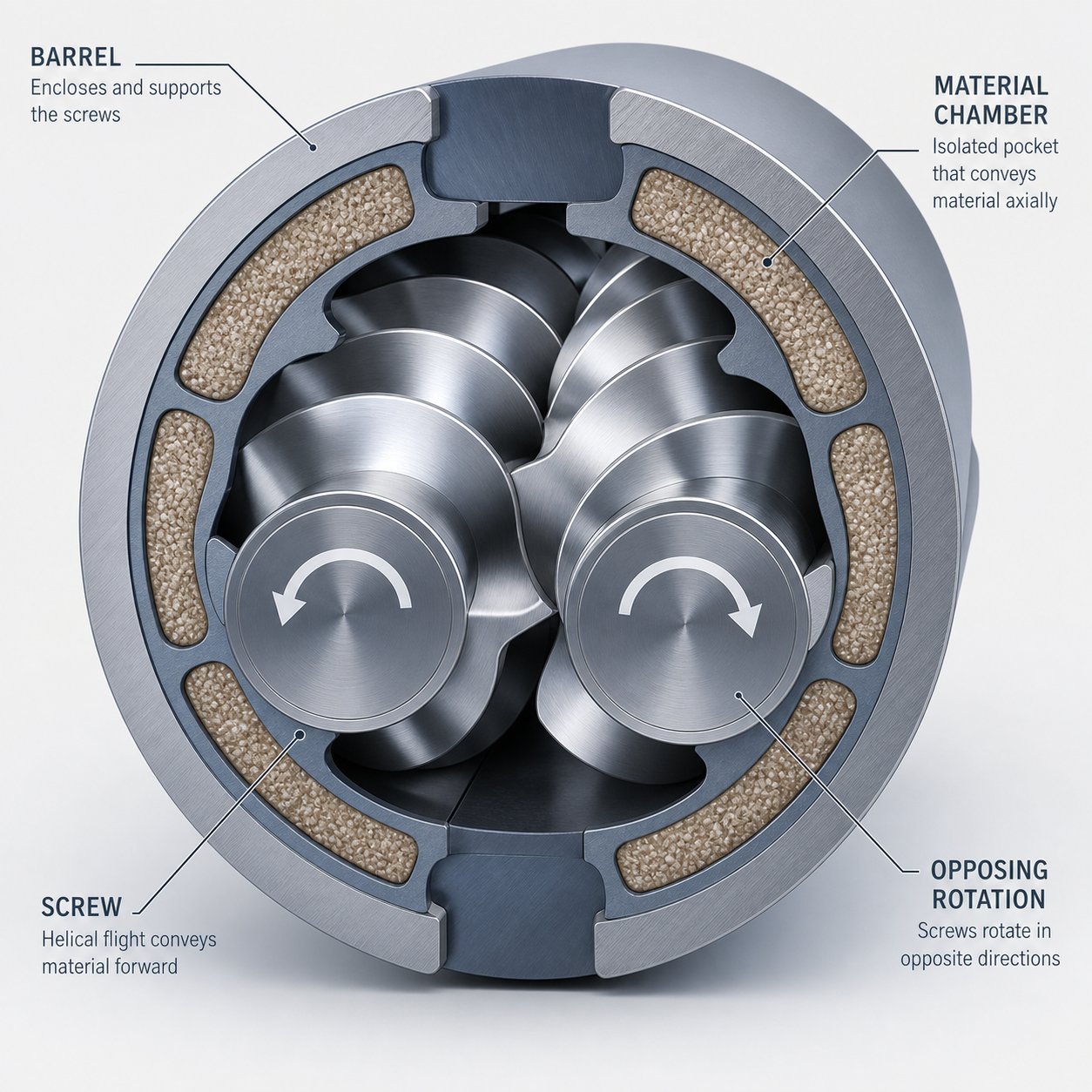
Here is how the mechanism actually works. When two screws intermesh while rotating in opposite directions, the flight of one screw enters the channel of the other. This creates a series of isolated compartments, often described as C-shaped chambers, between each pair of flights and the surrounding barrel wall. Material entering these chambers has essentially one path: forward, toward the die. There is very little opportunity for the polymer to slip backward or recirculate, which is exactly the behavior engineers want when processing sensitive formulations.
This positive displacement conveying characteristic makes the double screw extruder configuration mechanically distinct from drag-flow-dominant machines. Each "packet" of material travels through the barrel in a controlled, predictable manner, spending roughly the same amount of time at each processing temperature. You will notice that this behavior has enormous implications for materials that degrade quickly under heat, a topic explored in depth throughout this article.
Why This Extruder Type Still Matters
Co-rotating twinscrew extruders receive most of the industry attention, and for good reason. They excel at high-intensity compounding, reactive extrusion, and applications that demand aggressive dispersive mixing. Yet counter-rotating designs have never disappeared, and in certain sectors they remain the only viable choice.
PVC processing is the clearest example. PVC is notoriously heat-sensitive, degrading rapidly when exposed to excessive shear or prolonged thermal exposure. The low shear intensity and narrow residence time distribution offered by counter-rotating machines keep PVC safely within its processing window, something co-rotating designs struggle to replicate without significant compromise. Industries producing PVC pipes, profiles, and sheets depend on this gentle conveying behavior every day.
Beyond PVC, counter-rotating technology serves processors working with other shear-sensitive polymers, specialty masterbatches, and wood-plastic composites. The twinscrew configuration's ability to deliver consistent output with minimal thermal variation makes it an enduring engineering solution, not an outdated one.
Yet despite this ongoing relevance, detailed technical resources dedicated to counter-rotating extruders remain surprisingly thin. Most references lump them into a brief comparison with co-rotating machines, never exploring the mechanics, design subtypes, or application-specific engineering that make these extruders unique. The sections ahead fill that gap, starting with the positive displacement mechanism that defines everything about how these machines behave.
How the Positive Displacement Mechanism Works
Most descriptions of twin screw extrusion stop at the phrase "positive displacement" and move on, as if those two words explain everything. They do not. The real engineering story lies in how material actually moves through isolated chambers, why that isolation produces such uniform processing conditions, and what pressure dynamics it creates between the screws. Understanding these mechanics is what separates competent screw extrusion practice from guesswork.
The C-Shaped Chamber and Positive Displacement Conveying
Picture two intermeshing screws rotating in opposite directions inside a closely fitted barrel. The flight of one screw reaches into the channel of the other, and where they meet, the material path is effectively sealed. Between each pair of screw flights and the barrel wall, an enclosed pocket forms. Engineers call these C-shaped chambers because of their cross-sectional geometry, and they are the fundamental unit of material transport in this type of machine.
Each C-shaped chamber acts like a tiny, moving container. As the twin screws rotate, these containers advance along the barrel length, carrying their captured polymer with them. The material inside a given chamber has essentially nowhere to go except forward. It cannot leak backward past the tight intermeshing zone, and it cannot jump ahead to the next chamber. This is positive displacement conveying in its purest mechanical form: a fixed volume of material is physically pushed from the feed end toward the die with every revolution of the screws.
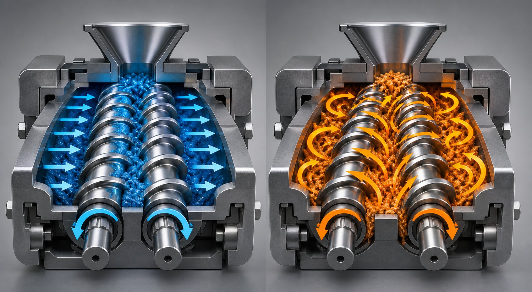
Contrast this with how a co-rotating twin screw extruder moves material. In co-rotating designs, the screws turn in the same direction and material is handed off from one screw to the other at the intermeshing region, following a figure-eight flow path. Transport depends heavily on drag flow, where the viscous polymer is pulled along by the rotating screw surfaces. The material can recirculate, mix aggressively, and experience vastly different flow histories depending on its position in the channel.
In a counter-rotating machine, that variability is deliberately minimized. Each packet of material is locked into its chamber, experiencing a controlled and predictable path through every heating zone, every compression stage, and every mixing section. You'll notice that this predictability isn't just a nice theoretical property. It has direct, measurable consequences for how the polymer behaves during the twin screw extrusion process, particularly when thermal sensitivity is a concern.
Residence Time Distribution and Why It Matters
Here is where the chamber isolation pays its biggest dividends: residence time distribution, often abbreviated as RTD. Residence time is simply how long a given particle of material stays inside the extruder, from the moment it enters the feed throat until it exits the die. In any extrusion process, not every particle spends exactly the same amount of time in the barrel. The spread of those times, the distribution, is what engineers care about.
In a counter-rotating twin screw extruder, the sealed C-shaped chambers create a remarkably narrow RTD. Because each chamber moves forward at the same rate, nearly all the material experiences approximately the same thermal history. There are no fast lanes and no slow lanes. No particle gets trapped in a recirculation zone while another rockets through the barrel ahead of schedule.
Co-rotating designs tell a different story. Their open flow channels and aggressive mixing elements intentionally recirculate material, which is excellent for dispersive mixing but terrible for RTD uniformity. Some polymer particles pass through quickly, while others loop back and endure significantly longer exposure to barrel temperatures. For thermally stable engineering plastics, that variability is tolerable. For heat-sensitive materials like rigid PVC, which has a narrow window between adequate fusion and thermal degradation, it can be catastrophic.
Think of it this way: if your processing window is only 10 to 15 degrees Celsius wide, you cannot afford a residence time spread that exposes some fraction of your material to barrel temperatures for twice as long as the rest. Degradation products form, discoloration appears, and mechanical properties collapse. The narrow RTD of counter-rotating designs keeps the entire material stream within that tight processing envelope, which is precisely why these machines dominate PVC pipe and profile production.
Pressure Generation Between the Screws
The positive displacement mechanism creates another characteristic that shapes everything about counter-rotating extruder design: localized high pressure at the intermeshing zone. Imagine material being pushed toward the center from both sides simultaneously. The left screw drives its C-shaped chambers inward. The right screw does the same from the opposite direction. Where these two material streams meet, between the screws, pressure spikes sharply.
This phenomenon is sometimes called the calendering effect, because the intermeshing region behaves somewhat like a pair of calender rolls compressing material between them. The polymer undergoes compressive and elongational deformation as it passes through this zone, providing a degree of dispersive mixing under relatively gentle conditions. That gentle dispersion is particularly effective for distributing additives in formulations like PVC compounds, where moderate mixing is more desirable than the aggressive particle breakup typical of co-rotating machines.
However, this inter-screw pressure comes with a significant engineering trade-off. The separation force generated at the intermeshing zone pushes the twin screws apart, creating bending loads on the screw shafts. At higher rotational speeds, these forces intensify rapidly. The screws can deflect toward the barrel wall, accelerating wear on both the screw flights and the barrel bore. Push the RPM too high, and you risk mechanical failure.
The localized pressure buildup at the intermeshing zone is the single most influential factor in counter-rotating extruder design. It dictates RPM limits, barrel engineering requirements, screw metallurgy choices, and bearing specifications. Every design decision traces back to managing this pressure.
This is why counter-rotating machines typically operate at much lower screw speeds than their co-rotating counterparts, often in the range of 30 to 150 RPM, while co-rotating extruders routinely run at 400 RPM or higher. The speed limitation is not a flaw in the design. It is a deliberate engineering response to a fundamental pressure characteristic that cannot be eliminated without losing the very positive displacement behavior that makes these machines valuable.
Barrel construction must also account for these pressure dynamics. The bore region near the intermeshing zone sees concentrated wear patterns unlike anything in a co-rotating or single-screw machine. Harder linings, tighter bore tolerances, and carefully selected metallurgies are all responses to this single mechanical reality. Even the way screw elements are configured along the barrel length reflects an ongoing effort to balance pressure generation with acceptable wear rates.
These pressure dynamics, combined with the chamber isolation and narrow RTD characteristics, form a complete mechanical picture that most references never assemble in one place. The conveying mechanism is not just "positive displacement." It is a system of interlocking behaviors where gentle transport, uniform thermal exposure, and concentrated inter-screw forces all flow from the same root cause: two screws, turning in opposite directions, trapping material in sealed chambers. Every engineering choice downstream, from screw element design to barrel metallurgy, is a response to this foundation.
Counter-Rotating Extruder Types and Classification
Not all counter-rotating twin screw extruders are built alike, and grouping them into a single category obscures critical differences in how they convey, mix, and process material. Two classification axes matter here: whether the screws actually intermesh, and whether the machine is designed for low-speed gentle processing or high-speed energy-intensive work. Getting this taxonomy right is the difference between specifying a machine that fits your process and one that fights it.
Intermeshing vs Non-Intermeshing Counter-Rotating Designs
The most fundamental design split comes down to screw engagement. In an intermeshing configuration, the flight of one screw fits tightly into the channel of the other. This is the geometry that produces those sealed C-shaped chambers discussed earlier, creating true positive displacement conveying with minimal backflow. The tight clearances between flights and channels mean each chamber is effectively isolated, giving you the narrow residence time distribution and predictable material transport that make these machines so well-suited for heat-sensitive polymers.
Non-intermeshing counter-rotating designs take a completely different approach. Here, two screws rotate in opposite directions inside the same barrel, but their flights never engage. A gap separates them, and material can flow relatively freely between the two screw channels. Imagine two independent single-screw extruders placed side by side in a shared housing. The conveying mechanism shifts from positive displacement toward drag flow, similar to what you'd see in a conventional single-screw machine. Shear intensity drops, self-wiping action disappears entirely, and mixing efficiency becomes more moderate.
So when would you choose one over the other? Intermeshing designs dominate applications demanding precise material control: PVC pipe and profile extrusion, shear-sensitive masterbatch processing, and any formulation where uniform thermal history is non-negotiable. Non-intermeshing configurations find their niche in processing thermally delicate or low-viscosity materials where even the moderate shear of intermeshing screws is too aggressive, including certain soft PVC compounds and thermoplastic elastomers. A parallel twin screw extruder in either configuration can be tailored to specific material requirements, but the intermeshing variant remains far more common in industrial practice.
HSEI and LSLF Classification Explained
Beyond the intermeshing question, there is a second classification framework that many engineers never encounter: the distinction between High Speed Energy Input (HSEI) and Low Speed Late Fusion (LSLF) machines. These represent two entirely different philosophies for how a twin screw compounding extruder or profile extruder should operate.
LSLF counter-rotating extruders are the traditional workhorses of PVC processing. They run at low screw speeds, typically up to 50 RPM, and use large-diameter screws to maximize volumetric throughput without relying on high rotational energy. The "late fusion" in their name reflects how PVC is processed in these machines: the polymer fuses gradually along the barrel length under gentle shear, avoiding the rapid energy input that would push PVC past its degradation threshold. These machines prioritize uniform pressure pumping and minimal thermal stress.
HSEI twin screw extruders occupy the opposite end of the spectrum. These machines are designed for energy-intensive operations like compounding, reactive processing, and devolatilization, with screw speeds reaching 1200 RPM or higher. The co-rotating intermeshing configuration dominates the HSEI category, though counter-rotating intermeshing and non-intermeshing versions serve specialty compounding twin screw extruder applications. HSEI designs use segmented screw elements on high-torque splined shafts, modular barrel sections with liquid cooling, and starve-fed operation where output rate is controlled by the feeder rather than screw speed.
The contrast between these two families is stark. Consider the following comparison:
| Parameter | LSLF (Low Speed Late Fusion) | HSEI (High Speed Energy Input) |
|---|---|---|
| Typical RPM Range | Up to 50 RPM | Up to 1,200+ RPM |
| Screw Geometry | Large diameter, often conical; continuous flights | Smaller OD/ID ratio; segmented modular elements on splined shafts |
| Primary Conveying Emphasis | Positive displacement with uniform pressure pumping | Drag flow with starve-fed, zero-pressure-gradient conveying |
| Energy Input | Low mechanical shear; relies more on barrel heat conduction | High mechanical shear via screw speed; motor-driven energy input |
| Dominant Rotation Direction | Counter-rotating | Primarily co-rotating (counter-rotating used for specialty tasks) |
| Target Applications | PVC pipe, profile, sheet, and similar heat-sensitive extrusion | Compounding, reactive extrusion, devolatilization, direct extrusion |
What this table reveals is that "counter-rotating" and "LSLF" overlap heavily but are not synonymous. Most LSLF machines are counter-rotating, but some counter-rotating extruders push into higher-speed territory for specific compounding tasks. Similarly, while HSEI is dominated by co-rotating designs, counter-rotating HSEI machines exist for applications requiring positive displacement at elevated throughput rates.
For process engineers evaluating equipment, the practical takeaway is straightforward: define your material sensitivity and mixing requirements first, then let those parameters guide you toward the correct classification. A PVC profile line almost certainly calls for an LSLF counter-rotating machine. A mineral-filled polypropylene compounding operation points toward an HSEI co-rotating system. The challenge arises with applications that sit between these poles, where screw element design and barrel configuration become the decisive variables rather than the machine family itself.
Counter Rotating vs Co Rotating Twin Screw Extruder Compared
Choosing between a co rotating twin screw extruder and a counter-rotating one is not a matter of which machine is "better." It is a matter of which mechanical behavior matches your material, your product geometry, and your process constraints. Yet most comparison resources flatten this decision into a handful of bullet points, ignoring the underlying physics that actually determines whether a machine will succeed or fail on your production floor.
The LSLF and HSEI classification discussed earlier already hinted at where these two families diverge. Here, the comparison gets specific: parameter by parameter, application by application, with the mechanical reasoning behind each trade-off made explicit.
Mechanical and Operational Differences at a Glance
Before diving into application scenarios, it helps to see the full landscape in one place. The table below contrasts co rotating and counter rotating twin screw extruder configurations across the parameters that matter most when specifying equipment or troubleshooting an existing line.
| Parameter | Counter-Rotating Twin Screw Extruder | Co-Rotating Twin Screw Extruder |
|---|---|---|
| Screw Rotation Direction | Opposite directions (one clockwise, one counterclockwise) | Same direction (both clockwise or both counterclockwise) |
| Primary Conveying Mechanism | Positive displacement via sealed C-shaped chambers | Drag flow with figure-eight material transfer at the intermeshing zone |
| Shear Intensity | Low to moderate | Moderate to high |
| Self-Wiping Capability | Limited; flights do not fully scrape opposing screw surfaces | Full self-wiping action between intermeshing screw flights |
| Typical RPM Range | Generally up to ~150 RPM; LSLF PVC machines often below 50 RPM | Commonly 200-600 RPM; high-performance units exceed 1,200 RPM |
| Mixing Behavior | Distributive-dominant; calendering effect provides moderate dispersive mixing | Both dispersive and distributive; kneading blocks deliver intense shear-driven mixing |
| Residence Time Distribution | Narrow and uniform due to chamber isolation | Broader; material recirculation creates variable thermal histories |
| Pressure Generation | High, stable; positive displacement builds consistent die pressure | Moderate; pressure fluctuates with degree of fill and screw design |
| Primary Applications | PVC pipe, profile, and sheet extrusion; WPC; shear-sensitive formulations | Polymer compounding, masterbatch, reactive extrusion, nanocomposites |
A few details in this table deserve closer attention. Notice the RPM gap: counter-rotating machines operate at a fraction of the speed that co-rotating designs routinely achieve. This is not a technological shortcoming waiting to be solved. It is a direct consequence of the inter-screw pressure buildup covered earlier. Pushing counter-rotating screws faster amplifies the separation forces at the intermeshing zone, risking deflection and accelerated wear. Co-rotating screws, by contrast, generate shear rather than compressive force at their intermeshing region, which is why they tolerate much higher rotational speeds without the same mechanical penalty.
The self-wiping difference is equally significant. In a co-rotating design, the flight tip of one screw continuously scrapes the root of the opposing screw, preventing material stagnation and thermal degradation on metal surfaces. Counter-rotating flights move in opposing directions at the nip point, creating a calendering action rather than a wiping action. This means counter-rotating machines can accumulate material in certain dead zones if screw geometry is poorly designed, a factor that directly influences how mixing elements must be configured.
When Counter-Rotating Is the Better Choice
There are processing scenarios where the gentle, controlled behavior of a counter-rotating machine is not just preferable but essentially mandatory. Recognizing these scenarios early prevents costly mismatches between equipment and application.
Heat-sensitive polymers demanding low shear. Rigid PVC remains the textbook case. Its thermal decomposition temperature sits dangerously close to its processing temperature, and excessive shear generates internal heat that pushes the polymer past its degradation threshold. The low shear intensity and minimal shear-induced heat generation of counter-rotating designs keep PVC safely within its narrow processing window. Co-rotating twin screw extruders can process PVC, but doing so requires significantly more sophisticated temperature control and often compromises throughput to stay within safe thermal limits.
Applications requiring precise residence time control. When your material degrades with even modest overexposure to barrel temperatures, the narrow residence time distribution of positive displacement conveying becomes a decisive advantage. Every particle of material spends roughly the same time at each processing zone, eliminating the "hot spots" and "cold spots" that plague drag-flow machines running thermally sensitive formulations.
Direct extrusion of finished products. PVC pipes, window profiles, siding panels, and sheets are typically extruded directly from the twin-screw extruders to the die, without an intermediate pelletizing step. This direct extrusion process demands stable, pulsation-free melt delivery at consistent pressure. The positive displacement mechanism of counter-rotating designs delivers exactly that: a steady, predictable melt stream with minimal pressure fluctuation, which translates directly into tighter dimensional tolerances on the finished product.
Consistent output independent of material variability. Because conveying volume is determined by chamber geometry and screw speed rather than by friction or material viscosity, counter-rotating machines maintain more stable output rates even when incoming material properties fluctuate. For processors handling recycled PVC or variable-lot feedstocks, this stability reduces scrap rates and keeps production on specification.
When Co-Rotating Is Preferred
Fairness matters in engineering comparisons, and co-rotating twin screw extruders earn their dominance in several important categories. Ignoring their genuine advantages would undermine the credibility of any comparison.
High-intensity compounding. When the goal is to disperse nanofillers, break down pigment agglomerates, or blend immiscible polymers into a uniform alloy, the intense shear fields generated by co-rotating screws are essential. Kneading blocks in a co-rotating compounding extruder impose complex deformation histories, combining shear and elongational flow to achieve dispersion levels that counter-rotating machines simply cannot match. Applications like carbon nanotube nanocomposites, high-filler-loading masterbatches, and engineering plastic blends rely on this capability.
Reactive extrusion. Chemical reactions performed inside the extruder, such as polymerization, grafting, or compatibilization, benefit from the aggressive mixing and controlled fill-level management that co-rotating designs provide. The self-wiping action prevents reactant buildup on screw surfaces, and the modular screw configuration allows engineers to position reaction zones, devolatilization sections, and cooling stages precisely along the barrel length.
High throughput with maximum flexibility. Co-rotating machines accept a much wider range of screw element configurations, from gentle conveying sections to aggressive reverse elements, in virtually unlimited combinations. This modularity lets a single machine handle dozens of different formulations with only a screw swap. For contract compounders processing diverse materials week to week, that flexibility outweighs the gentler handling of counter-rotating designs.
Devolatilization and moisture removal. Removing volatiles, solvents, or moisture from the polymer melt requires open screw channel geometry and precise vacuum staging. Co-rotating twin screw extruders excel here because their partially filled channels and self-wiping behavior maximize the exposed melt surface area under vacuum, achieving high devolatilization efficiency that sealed C-shaped chambers cannot replicate.
The pattern that emerges is clear: counter-rotating designs protect the material from the process, while co-rotating designs harness the process to transform the material. Neither philosophy is universally superior. The right choice follows directly from what your material needs and what your end product demands. And once that choice is made, the critical engineering question shifts from the machine itself to the components inside it, particularly the screw elements that define how each zone in the barrel actually handles the polymer.
Screw Element Design and Modular Twin Screw Configurations
Screw elements are where engineering intent becomes physical reality inside the barrel. In a co-rotating machine, swapping kneading blocks or adjusting stagger angles is routine, and extensive guides exist for that platform. Counter-rotating designs, however, play by different rules. The same element categories exist, conveying, kneading, and mixing, but the geometry, tolerances, and functional behavior of each type diverge sharply from their co-rotating counterparts. Understanding those differences is essential for anyone configuring or troubleshooting screw extruders in this family.
Conveying Elements and Flight Geometry
Conveying elements in a counter-rotating twin screw extruder must do something their co-rotating equivalents do not: form airtight seals. Because the positive displacement mechanism depends on isolated C-shaped chambers, the flight of one screw must mesh precisely into the channel of the other with minimal clearance. Even small gaps between flights and opposing channels allow material to leak backward, undermining the very principle that makes counter-rotating conveying predictable.
This demands significantly tighter manufacturing tolerances than co-rotating designs require. Where a co-rotating element relies on self-wiping geometry to maintain clearances functionally, a counter-rotating element depends on dimensional precision at the point of manufacture. Worn or poorly machined flights do not just reduce efficiency; they fundamentally change the conveying mechanism from positive displacement toward uncontrolled drag flow.
Pitch variations along the screw length control how fast material moves and how much pressure builds in each zone. Larger pitch elements increase volumetric throughput per revolution but generate less pressure, making them ideal for feed sections where the goal is simply to accept incoming material. Shorter pitch elements slow conveying speed, increase the local fill level, and build the pressure needed to push polymer through downstream restrictions and ultimately through the die.
Beyond pitch, the overall screw geometry matters enormously. Two configurations dominate the market: conical and parallel. Conical screws taper from a large diameter at the feed end to a smaller diameter at the discharge. This progressive compression naturally densifies material as it moves forward, making conical designs particularly well-suited for processing bulk powders like PVC dry blends that need gradual compaction. Parallel twin screw geometries maintain a constant diameter throughout, offering more uniform channel depth and simpler element interchangeability. Each geometry shapes the pressure profile, residence time, and energy input differently, and the choice between them typically follows the material and application rather than personal preference.
Kneading and Mixing Elements in Counter-Rotating Configurations
Sounds complex? It gets more nuanced when mixing enters the picture. Kneading blocks in co-rotating machines work by staggering multiple discs at angular offsets, 30, 45, 60, or 90 degrees, to generate controlled shear through repeated deformation of the melt. The self-wiping action of co-rotating screws continuously cleans material off disc surfaces, preventing stagnation and ensuring uniform thermal exposure even in high-shear zones.
Counter-rotating kneading elements face a fundamentally different challenge. Because the screws do not self-wipe as effectively, any mixing element design must account for the risk of material stagnating on disc surfaces or in dead zones between elements. Stagnant polymer exposed to barrel temperatures for extended periods can degrade, forming black specks, gels, or discolored streaks in the finished product. This risk constrains how aggressively mixing elements can be designed. In practice, counter-rotating mixing sections tend to rely more on distributive mixing, splitting and recombining the melt flow, rather than the intense dispersive shear that co-rotating kneading blocks deliver.
The modular nature of modern twin screw systems gives processors the flexibility to customize screw profiles for specific formulations. By arranging conveying, kneading, and mixing elements in different sequences along a splined shaft, engineers can fine-tune the balance between material transport, melt homogenization, and pressure generation within a single barrel. A PVC profile line might use predominantly conveying elements with a short, gentle mixing section, while a filled compound application could incorporate more kneading zones, accepting slightly higher shear in exchange for better additive dispersion.
Barrel Design and the Screw-Barrel Relationship
Screws do not operate in isolation. The twin screw and barrel system must be engineered as an integrated unit, because screw geometry, barrel bore tolerances, and thermal management all interact to determine plasticizing consistency and equipment longevity. Treating the barrel as a passive housing and the screws as the only active component is a common mistake that leads to premature wear, inconsistent output, and avoidable production losses.
Modern twin screw barrel designs use segmented construction, where the barrel is divided into individual sections typically four to six diameters long. Each section can be independently heated and cooled, giving the process engineer precise temperature control zone by zone. As Plastics Technology notes, the segmented approach also allows open barrel sections for feeding and venting to be positioned at specific locations along the barrel length, a configurability that fixed-barrel designs simply cannot offer.
Wear-resistant linings are critical, especially in counter-rotating machines where the intermeshing zone concentrates abrasive and compressive forces. Bimetallic barrel liners and hardened sleeve inserts protect the bore from the accelerated wear patterns unique to counter-rotating pressure dynamics. The bore itself must be machined to tight tolerances; even slight deviations in the figure-eight bore geometry increase screw-to-barrel clearance, allowing material leakage that degrades conveying efficiency and melt quality.
Here is a summary of the key screw element types used in counter-rotating configurations and their primary functions:
- Large-pitch conveying elements: High volumetric throughput with low pressure generation; used in feed zones to accept incoming material efficiently.
- Short-pitch conveying elements: Increased fill level and pressure buildup; positioned before the die or upstream of restrictive mixing sections.
- Kneading blocks: Controlled shear and melt homogenization; designed with stagnation risk in mind for counter-rotating applications.
- Toothed or gear-type mixing elements: Distributive mixing through repeated melt splitting and recombination; minimal temperature rise compared to kneading blocks.
- Reverse elements: Localized back-pressure generation and melt sealing; used upstream of vent zones or to increase residence time in specific barrel sections.
Every element in this list interacts with the barrel section surrounding it. A kneading block positioned in a barrel zone with insufficient cooling will overheat shear-sensitive material. A venting element placed in a closed barrel section cannot perform its function. The twin screw barrel layout and the screw profile must be designed together, each informing the other, to create a processing system that delivers consistent results over thousands of production hours.
Getting screw elements and barrel configuration right is an engineering exercise. Translating that exercise into real-world production results, however, requires mapping these mechanical capabilities to specific materials and end products, where the choice of extruder configuration either enables or limits what you can manufacture.
Key Industrial Applications for Counter Rotating Extruders
Screw elements and barrel segments are engineering tools. Their value only materializes when they solve a specific processing problem for a specific material. Counter-rotating twin screw extruders do not earn their place in factories because of elegant mechanical principles. They earn it because certain polymers and certain products simply perform better, or only work at all, when processed under the gentle, controlled conditions these machines provide. Mapping those applications to the machine characteristics that enable them reveals why this extruder family remains indispensable.
PVC Pipe and Profile Extrusion
PVC is the material that defines counter-rotating technology. Why? Because rigid PVC begins to thermally degrade at roughly 140 degrees Celsius, yet it needs to reach fusion temperatures near 170 to 190 degrees Celsius to form a cohesive melt. That leaves an extraordinarily tight processing window, sometimes as narrow as 10 to 15 degrees. Push too hard with excessive shear, and you generate frictional heat that tips the material past its degradation threshold. Allow too much residence time variation, and some fraction of the polymer overcooks while the rest remains under-fused.
Every mechanical characteristic discussed earlier in this article converges to solve this exact problem. The sealed C-shaped chambers deliver positive displacement conveying with minimal back-mixing, keeping residence time distribution narrow. Low screw speeds, often below 50 RPM for LSLF machines, limit shear-induced heat generation. The calendering effect at the intermeshing zone provides just enough dispersive action to distribute stabilizers and lubricants without thermally abusing the base resin.
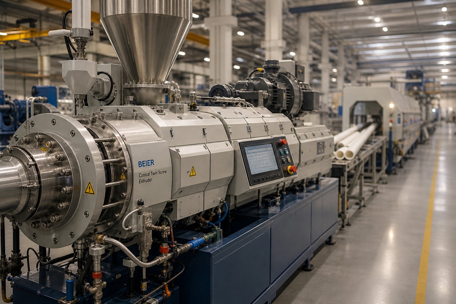
The conical twin screw extruder configuration is particularly dominant in PVC pipe, profile, and sheet production. Its tapering screw geometry provides progressive compression from a large-diameter feed section to a smaller-diameter discharge, gradually densifying PVC dry-blend powder into a homogeneous melt. This progressive approach matches PVC's unique fusion behavior: the material does not melt like a conventional thermoplastic but instead fuses through a series of grain-boundary softening stages that benefit from gradual mechanical energy input rather than sudden shear spikes.
As Rollepaal notes, conical machines historically offered mechanical advantages for PVC extrusion, though parallel counter-rotating designs are increasingly favored for larger extruder sizes due to greater screw design freedom and wider processing windows. For many twin screw extruder plastic processing lines, particularly those producing UPVC pipes, window profiles, door frames, and drainage systems, the conical counter-rotating configuration remains the production workhorse.
WPC and Specialty Polymer Processing
Wood-plastic composite extrusion represents one of the fastest-growing application areas for counter-rotating machines. WPC formulations typically combine polyethylene or PVC with 40 to 70 percent wood fiber or flour filler. This creates a doubly challenging processing scenario: the wood fibers are abrasive, accelerating screw and barrel wear, and they are thermally sensitive, charring and releasing volatiles at temperatures above roughly 200 degrees Celsius.
A plastic twin screw extruder in a counter-rotating configuration handles both challenges simultaneously. The low shear environment prevents excessive heat generation that would char wood fibers and release odorous volatiles. The positive displacement conveying maintains stable output despite the high filler loading, which can make drag-flow-dependent machines struggle with inconsistent feed behavior. Counter-rotating intermeshing conical extruders are especially popular for WPC decking, fencing, and cladding production, where the conical geometry provides the compression needed to consolidate highly filled formulations into dense, bubble-free profiles.
Beyond WPC, counter-rotating machines serve several other specialty niches. Certain thermoset pre-mixes, including phenolic and melamine-based compounds, require gentle processing to avoid premature crosslinking inside the barrel. Shear-sensitive masterbatches containing heat-reactive pigments or temperature-limited additives also benefit from the controlled thermal exposure these machines provide. Even in granulation applications, where a screw extruder granulator processes sensitive formulations into pellets, the counter-rotating platform offers thermal control that co-rotating alternatives struggle to match at equivalent throughput.
Matching Your Application to the Right Barrel and Screw System
Selecting the right extruder platform is only half the equation. The screw and barrel system inside that platform determines whether your process delivers consistent quality shift after shift or fights you with degradation, wear, and dimensional variation. Two identical twin screw plastic extruder machines running the same PVC formulation can produce dramatically different results if one has properly specified screws and barrels and the other does not.
Several factors drive this specification process. Material abrasiveness dictates metallurgy: high calcium carbonate loadings in PVC or WPC compounds demand hardened barrel liners and wear-resistant screw flight surfaces. Processing temperature sensitivity determines how precisely barrel bore tolerances must be held, because even small clearance increases allow material leakage past the C-shaped chambers, broadening residence time distribution and undermining the very advantage that justified choosing a counter-rotating machine. Surface treatments and coatings extend service life in corrosive environments, particularly when processing CPVC or chlorinated compounds that release hydrochloric acid during thermal degradation.
For manufacturers processing PVC pipe, PVC profile, PVC sheet, or WPC who need custom or replacement conical twin screw barrels, sourcing from a supplier with application-specific expertise matters. NANHAIYA's Conical Twin Screw Barrel line is engineered specifically for these applications, with a focus on consistent plasticizing performance and dimensional precision that supports long production runs without quality drift.
The following list maps key application sectors to their most common extruder and screw-barrel configuration preferences:
- Rigid PVC pipe (UPVC): Counter-rotating intermeshing conical extruder; nitrided or bimetallic barrel linings; screw geometry optimized for gradual fusion of PVC dry blends.
- PVC window and door profiles: Counter-rotating conical configuration; precision bore tolerances critical for surface finish quality; multi-zone barrel temperature control.
- PVC sheet and film: Counter-rotating conical or parallel designs depending on sheet width and output requirements; barrel cooling capacity essential for preventing over-fusion near the die.
- Wood-plastic composites (WPC): Counter-rotating conical extruder with hardened wear surfaces; screw elements designed for high-filler compaction; venting sections to release moisture and wood volatiles.
- Shear-sensitive masterbatches: Counter-rotating parallel or conical extruder at low RPM; gentle mixing elements to distribute pigments without thermal damage.
- Thermoset pre-mix processing: Counter-rotating design with short barrel length to minimize residence time; temperature-controlled zones to prevent premature cure.
- Specialty granulation (screw extruder granulator applications): Counter-rotating configuration for pelletizing heat-sensitive compounds; precise die pressure control for uniform pellet geometry.
Each of these applications demands a screw and barrel system tailored to its specific material challenges. A barrel engineered for rigid PVC pipe will not perform optimally for WPC without modifications to wear protection, venting placement, and compression ratio. This is precisely why working with suppliers who understand the relationship between barrel metallurgy, bore geometry, and application-specific processing demands is so critical to long-term production success.
Matching the right machine to the right application solves most processing problems before they start. But even the best-specified counter-rotating extruder operates within real mechanical constraints, and understanding those limitations honestly is what separates experienced processors from ones still learning expensive lessons on the production floor.
Mechanical Limitations and Modern Engineering Solutions
Every twin screw extruder machine design involves trade-offs, and counter-rotating configurations are no exception. The same positive displacement mechanism that delivers gentle, uniform conveying also introduces mechanical stresses that constrain how hard and how fast these machines can be pushed. Pretending those constraints do not exist helps no one. Understanding them, quantifying them, and engineering around them is what keeps production lines running reliably for tens of thousands of hours.
RPM Constraints and Screw Deflection Challenges
Imagine material being squeezed from both sides into the narrow intermeshing zone between two counter-rotating screws. As rotational speed increases, the volume of material dragged into that nip region per unit time increases proportionally, and the pressure spike between the screws grows rapidly. This generates a separating force that pushes the two screws apart, deflecting each screw shaft toward the barrel wall like a loaded cantilever beam.
How large are these forces? Research published in Polymers measured separating forces exceeding one metric ton on each screw in a relatively small 55 mm diameter laboratory extruder processing rigid PVC. Scale that up to production-sized double screw extruder machines with 90 mm or larger diameters and screw lengths of several meters, and the bending loads become enormous. Larger screws also carry significant self-weight, compounding the deflection problem through gravity alone.
This is precisely why production-scale closely intermeshing counter-rotating extruders are generally limited to 150 RPM and below, with large-diameter LSLF machines often restricted to less than 50 RPM. Exceeding these thresholds does not just risk accelerated wear. It risks catastrophic screw contact with the barrel bore, a failure mode that can destroy both components in minutes.
Pressure Buildup and Wear Patterns
The separating forces do not just deflect the screws. They press the screw flights against specific regions of the barrel bore, creating characteristic wear patterns that experienced maintenance engineers recognize immediately. In a counter-rotating screw extruder, maximum wear concentrates in the region between roughly 30 and 60 degrees from the vertical on each barrel bore, a zone the industry informally calls the "ten o'clock and two o'clock position."
The same MDPI study confirmed this through both pressure measurements and bore diameter inspections on a 90 mm barrel that had processed highly filled PVC for over 10,000 hours. The resultant force direction, determined experimentally, pointed consistently at approximately 30 degrees from vertical, aligning precisely with the zone of heaviest barrel wear. Numerical simulations corroborated the finding, predicting force angles between 18 and 25 degrees, with the difference attributed to gravity effects absent in the two-dimensional model.
This directional wear pattern differs fundamentally from co-rotating machines, where self-wiping action distributes contact forces more evenly around the barrel circumference. In counter-rotating designs, the asymmetric loading concentrates material removal in a narrow angular band, meaning the barrel bore gradually loses its circular cross-section. Once that distortion exceeds tolerance limits, chamber sealing degrades, positive displacement efficiency drops, and output consistency suffers.
Modern Engineering Solutions and Design Adaptations
These limitations are real, but they are also well-characterized and manageable. Decades of industrial experience have produced a toolkit of engineering countermeasures that allow counter-rotating twin screw extruder machines to deliver reliable service lives measured in years, not months.
Metallurgy has evolved dramatically. As ENTEK's materials engineering team has documented, the industry has shifted from predominantly nitrided tool steels toward Hot Isostatic Pressed (HIP) alloys, which now represent the majority of wear-part production for demanding applications. HIP materials deliver substantially higher abrasive wear resistance, while bimetallic screw construction places the hardest material on the outer wear surfaces and maintains a tougher, more ductile core to resist torque overloads and breakage.
Barrel technology has kept pace. Replaceable liner systems allow worn bore surfaces to be swapped without discarding the entire barrel body, which contains expensive machined features like cooling passages, thermocouple wells, and injection ports. This approach significantly reduces the long-term cost of ownership for any twin screw extruder machine operating in abrasive or high-pressure applications.
Beyond materials, optimized screw geometries reduce the severity of inter-screw pressure peaks. Adjusting flight clearances, modifying pitch transitions, and incorporating relief channels near the intermeshing zone can lower peak separating forces without sacrificing positive displacement efficiency. Precision CNC manufacturing holds tighter tolerances for longer, extending the interval before clearance-related performance degradation sets in.
The following list maps the most common operational issues to their engineering countermeasures:
- Screw deflection toward barrel wall: Shorter unsupported screw lengths, increased shaft diameter where possible, and optimized bearing arrangements to reduce cantilever loading.
- Uneven barrel bore wear at 30-60 degree positions: HIP or bimetallic barrel liners with hardness exceeding 60 HRC in the high-wear zone; replaceable liner systems for cost-effective refurbishment.
- Inter-screw pressure spikes at high RPM: Controlled calender gap design, optimized flight-to-core clearances, and operational speed limits matched to material viscosity and formulation abrasiveness.
- Inconsistent output from worn C-shaped chambers: Tighter manufacturing tolerances on new screw elements, periodic clearance measurement programs, and scheduled element replacement before performance degrades beyond acceptable limits.
- Corrosive wear from PVC or CPVC degradation byproducts: High-chromium tool steels or nickel-chromium alloys for barrel liners; corrosion-resistant coatings on screw flight surfaces.
Counter-rotating extruder limitations are not design flaws waiting to be eliminated. They are predictable mechanical consequences of the positive displacement principle, and they respond directly to proper metallurgy, geometry optimization, and disciplined maintenance practices.
The honest takeaway? A well-engineered counter-rotating machine, built with appropriate materials and maintained on a data-driven schedule, delivers production reliability that matches or exceeds any other extruder platform within its intended application range. The constraints only become problems when they are ignored during specification, when component quality is compromised during sourcing, or when maintenance intervals are stretched past the point where clearance measurements justify continued operation. Each of those failure modes traces back to a decision, not to an inherent flaw in the technology itself. Making those decisions well requires a structured framework for selecting and specifying the screw and barrel components that ultimately determine how long your machine holds its performance edge.
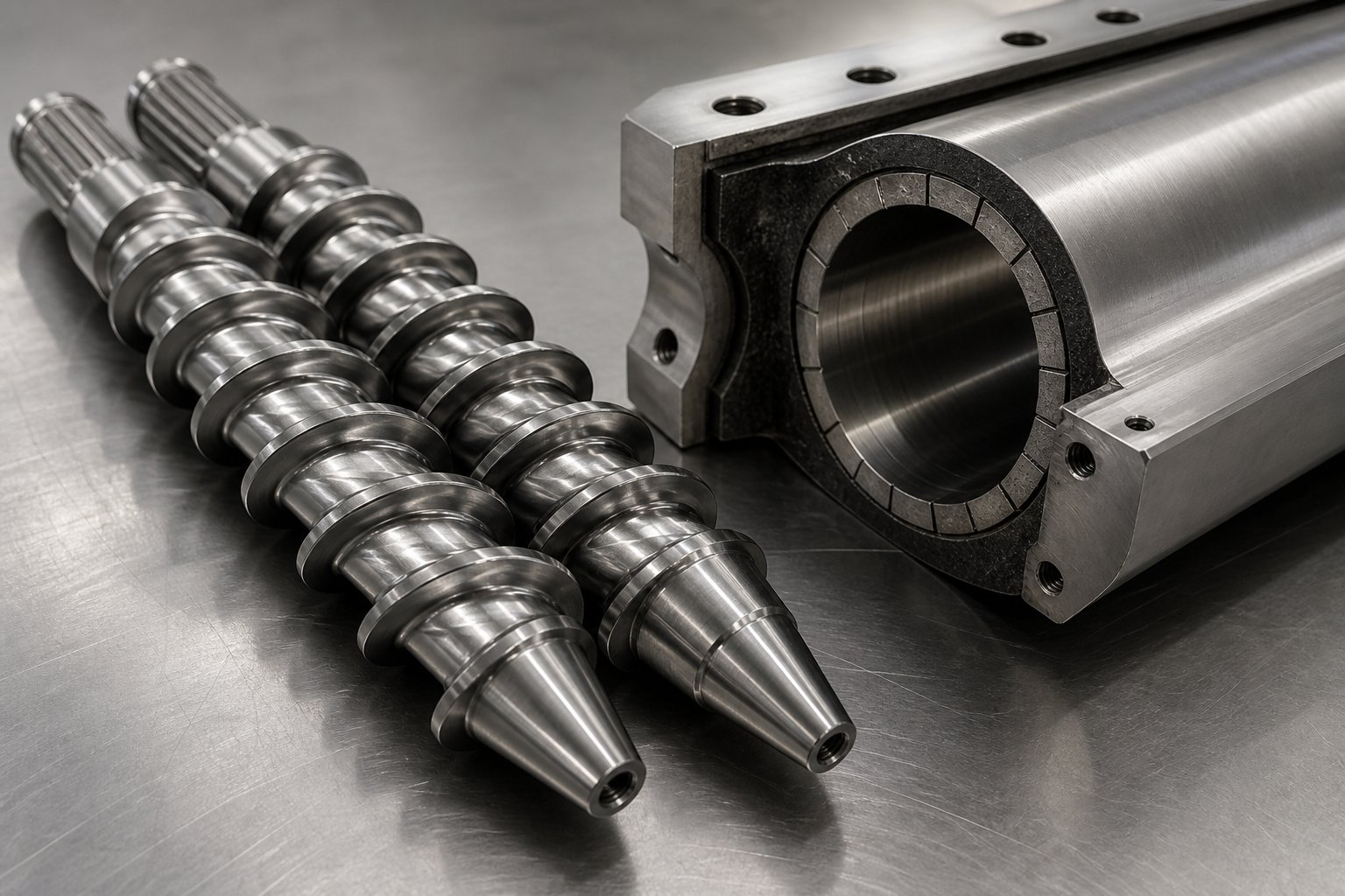
Selecting the Right Screw and Barrel for Your Twin Screw Extruder
Decisions about extruder selection and component specification tend to happen in the wrong order. Engineers browse twin screw extruder manufacturers, compare machine sizes, request quotes, and only then ask whether the screw and barrel system actually fits the material. That sequence is backwards. The material dictates the machine, the machine dictates the components, and the components dictate long-term production economics. Reversing this logic is how experienced processors avoid the expensive cycle of mismatched equipment, premature wear, and inconsistent output.
A Decision Framework for Extruder Selection
Rather than starting with equipment catalogs, start with the polymer sitting in your warehouse. Every specification choice downstream flows from a handful of material and application questions answered in the right sequence. Here is the decision framework that practicing process engineers use, whether they are commissioning a full-scale production line or evaluating a lab scale twin screw extruder for formulation development.
- Characterize your material's thermal sensitivity and melt behavior. Is the polymer heat-sensitive like PVC, where a narrow processing window demands low shear and tight residence time control? Or is it thermally robust like polyethylene, tolerating aggressive mixing without degradation risk? This single question eliminates entire extruder families from consideration. Rigid PVC dry blends point directly toward counter-rotating configurations. Engineering plastics intended for compounding with high filler loadings point toward co-rotating designs.
- Define the end product geometry and quality requirements. Are you extruding a finished pipe, profile, or sheet directly from the machine? Or are you producing pellets for downstream reprocessing? Direct extrusion of finished products demands the stable, pulsation-free melt delivery that positive displacement conveying provides. Pelletizing operations for compounding may tolerate the pressure fluctuations inherent in drag-flow machines, especially when aggressive mixing is the primary goal.
- Establish throughput targets and production scale. A laboratory twin screw extruder or benchtop twin screw extruder running at 2 to 10 kg/h serves formulation development and process validation, but the screw and barrel geometry must still reflect production-scale conditions to generate meaningful data. Production machines processing 200 to 500 kg/h of PVC pipe compound demand entirely different mechanical specifications, metallurgical choices, and maintenance intervals. Match your throughput requirement to the screw diameter and L/D ratio that achieves it without pushing the machine past 80 percent of its rated torque capacity.
- Assess material abrasiveness and corrosiveness. Highly filled PVC compounds containing calcium carbonate, wood-plastic composite formulations loaded with abrasive fibers, and CPVC blends releasing hydrochloric acid during processing each impose specific metallurgical demands on screws and barrel liners. Skipping this assessment leads to premature wear, bore distortion, and the clearance-related performance degradation discussed in the previous section.
- Select the extruder configuration that satisfies all four criteria simultaneously. Only after answering the material, product, throughput, and wear questions should the conversation shift to specific machine models. For most PVC and WPC applications, the answer will be a counter-rotating intermeshing machine, often in a conical configuration. For high-intensity compounding, the answer will almost always be a co-rotating parallel twin-screw extruder machine. The edge cases, shear-sensitive masterbatches, specialty thermosets, moderate-filler compounds, require the most careful analysis and often benefit from trial runs on a laboratory twin screw extruder before committing to production-scale capital.
Specifying Screw and Barrel Components for Long-Term Performance
The extruder platform is the stage. The screw and barrel components are the performers. And their specification is the single most consequential factor in determining whether your production line delivers consistent quality for years or fights you with escalating reject rates after the first few thousand hours of operation.
Three specification parameters deserve the most attention:
Metallurgy matched to material abrasiveness. Standard nitrided steel barrels serve lightly filled PVC compounds adequately, but the moment calcium carbonate loading exceeds 15 to 20 parts per hundred resin, or wood fiber enters the formulation, wear rates accelerate sharply. Bimetallic barrel liners with iron-boron alloy coatings, or HIP (Hot Isostatic Pressed) alloy liners, provide the abrasion resistance that keeps bore tolerances intact across extended production campaigns. Screw flight surfaces face the same challenge and benefit from hardened overlays or tool-steel construction.
Bore tolerances for plasticizing consistency. In a counter-rotating machine, the sealed C-shaped chambers only function as intended when screw-to-barrel clearances remain within specification. A bore diameter deviation of just 0.05 mm beyond tolerance can measurably degrade positive displacement efficiency, broadening residence time distribution and reintroducing the thermal variability that the counter-rotating design exists to eliminate. Precision-machined bores with documented dimensional inspection reports are not optional. They are the foundation of consistent plasticizing.
Surface treatments for extended service life. Corrosion-resistant coatings protect against the hydrochloric acid that PVC and CPVC compounds release during thermal degradation. Chrome plating, nickel-based alloy coatings, and specialized PVD treatments each address different corrosion and wear profiles. The right choice depends on the specific material chemistry, processing temperature range, and the desired interval between barrel refurbishment cycles.
For processors running PVC pipe, PVC profile, PVC sheet, or WPC lines who need custom or replacement conical twin screw barrels, NANHAIYA's Conical Twin Screw Barrel line addresses exactly these specification demands. Their barrels are engineered for consistent plasticizing performance across extended production runs, with dimensional precision and metallurgical options tailored to the material challenges that counter-rotating conical extruders face daily. For processors evaluating a twin-screw extruder machine barrel replacement or specifying components for a new line, having a supplier that understands the relationship between bore geometry, material abrasion profiles, and plasticizing consistency can meaningfully reduce both initial commissioning time and long-term cost of ownership.
Evaluating Manufacturers and Suppliers
Not every twin-screw extruder manufacturer or component supplier delivers the same level of precision, material quality, or application knowledge. When sourcing screws and barrels, particularly for counter-rotating machines where tolerance sensitivity is higher than in co-rotating designs, a structured evaluation process prevents costly mistakes.
What should you look for? The following criteria separate suppliers who genuinely support production performance from those who simply ship commodity parts:
- Material certifications and traceability: Reputable suppliers provide documented material certifications for barrel alloys and screw steels, including hardness test reports, chemical composition analysis, and heat treatment records. Without these, you have no way to verify that the metallurgy matches what was specified.
- Dimensional precision guarantees: Request bore diameter inspection reports with measurements at multiple points along the barrel length. Suppliers confident in their machining quality will provide these as standard documentation, not as an exception granted under pressure.
- Customization capabilities: Counter-rotating screw and barrel systems are not one-size-fits-all. Your barrel may need specific cooling channel layouts, venting port locations, or liner hardness profiles that differ from the supplier's standard catalog. Evaluate whether the supplier can accommodate application-specific modifications without excessive lead times or engineering surcharges.
- Technical support for application optimization: The best component suppliers do more than manufacture parts. They offer guidance on metallurgy selection for specific formulations, recommend bore tolerance specifications based on processing conditions, and provide wear-pattern analysis to optimize replacement intervals. This kind of support is especially valuable for processors running challenging materials like highly filled PVC or abrasive WPC compounds.
- Lead time and production continuity support: A barrel that takes six months to deliver when your current one is at end-of-life is a production shutdown waiting to happen. Evaluate supplier lead times realistically and consider maintaining a relationship with a supplier who can provide replacement components on a timeline that protects your uptime.
The decision framework outlined here, from material characterization through component specification to supplier evaluation, is not a theoretical exercise. It is the process that separates production lines delivering consistent quality at target costs from those burning capital on avoidable wear, unexpected downtime, and reactive troubleshooting. Every step in this framework traces back to the mechanical realities covered throughout this article: the positive displacement conveying that demands tight tolerances, the inter-screw pressure dynamics that drive specific wear patterns, and the thermal sensitivity of materials like PVC that leave no margin for imprecise engineering. Getting these decisions right at the specification stage is always less expensive than correcting them on the production floor.
Frequently Asked Questions About Counter Rotating Twin Screw Extruders
1. What is the main difference between counter rotating and co rotating twin screw extruders?
The core difference lies in how each design moves material through the barrel. Counter rotating twin screw extruders use two screws turning in opposite directions to create sealed C-shaped chambers that push polymer forward through positive displacement. This produces low shear, narrow residence time distribution, and gentle conveying ideal for heat-sensitive materials like PVC. Co-rotating extruders spin both screws in the same direction, relying on drag flow and figure-eight material transfer to generate intense shear and aggressive mixing suited for compounding, reactive extrusion, and high-filler dispersions. Counter rotating machines typically run below 150 RPM due to inter-screw pressure constraints, while co-rotating units routinely exceed 400 RPM.
2. Why are counter rotating twin screw extruders preferred for PVC processing?
Rigid PVC has an extremely narrow processing window, often just 10 to 15 degrees Celsius between adequate fusion and thermal degradation. Counter rotating extruders address this challenge through three mechanisms: low shear intensity that minimizes frictional heat generation, sealed C-shaped chambers that ensure nearly uniform residence time for every polymer particle, and positive displacement conveying that delivers stable, pulsation-free melt flow. Conical counter rotating configurations are especially favored because their tapering geometry provides progressive compression matching PVC's unique grain-boundary fusion behavior. Suppliers like NANHAIYA offer conical twin screw barrels specifically engineered for PVC pipe, profile, sheet, and WPC applications where consistent plasticizing performance is critical.
3. What are the mechanical limitations of counter rotating twin screw extruders?
The primary limitation stems from localized high pressure at the intermeshing zone. As both screws push material toward the center simultaneously, separating forces deflect the screw shafts toward the barrel wall. Research has measured forces exceeding one metric ton per screw on relatively small 55 mm machines. This constrains operational RPM, typically below 150 RPM for intermeshing designs, and creates characteristic wear patterns concentrated at the 30 to 60 degree positions on the barrel bore. Modern engineering solutions include HIP (Hot Isostatic Pressed) alloy barrel liners, bimetallic screw construction, optimized flight geometries that reduce peak pressure, and precision CNC manufacturing that holds tighter tolerances for longer service intervals.
4. What is the difference between HSEI and LSLF twin screw extruders?
HSEI (High Speed Energy Input) and LSLF (Low Speed Late Fusion) represent two fundamentally different processing philosophies. LSLF machines operate at low screw speeds, typically below 50 RPM, using large-diameter screws for gentle, gradual polymer fusion. They are the traditional workhorses for PVC pipe and profile extrusion where thermal sensitivity demands minimal mechanical energy input. HSEI extruders run at speeds up to 1,200 RPM or higher, using segmented modular screw elements on splined shafts to deliver high mechanical shear for compounding, reactive extrusion, and devolatilization. While most LSLF machines are counter rotating and most HSEI machines are co-rotating, the categories are not perfectly synonymous.
5. How do you select the right screw and barrel for a counter rotating twin screw extruder?
Start by characterizing your material's thermal sensitivity and abrasiveness, then define your end product requirements, throughput targets, and wear conditions. For PVC and WPC applications, metallurgy selection is critical: standard nitrided barrels work for lightly filled compounds, but calcium carbonate loadings above 15 to 20 phr or wood fiber fillers demand bimetallic or HIP alloy barrel liners. Bore tolerances must be held tightly because even 0.05 mm deviation degrades the positive displacement mechanism. When evaluating suppliers, prioritize documented material certifications, dimensional inspection reports, customization capabilities for application-specific needs, and technical support for optimizing metallurgy and wear resistance to your specific formulation.
Written by
Nanhaiya Technical Team
Zhoushan Nanhaiya Plastic Machinery Co., Ltd.
The Nanhaiya technical team supports screw and barrel manufacturing projects through application review, technical communication, custom manufacturing coordination, and production and quality control.
Discuss Your Application
Related Articles
More insights on screw barrel technology and plastics processing.

Extruder Machine Decoded: From Raw Pellet To Finished Product
Oct 6, 2026
Learn how an extruder machine works, compare single-screw vs. twin-screw types, and get expert guidance on specs, troubleshooting, and selection.
Read Article
PE Pipe Making Machine Decoded: From Raw Resin to Flawless Pipe
Oct 4, 2026
Learn how a PE pipe making machine works, from resin to finished pipe. Covers components, material grades, automation, troubleshooting, and buyer selection tips.
Read Article
PVC Profile Making Machine Decoded: From Raw Resin To Profit
Oct 3, 2026
Learn how a PVC profile making machine works — extrusion process steps, key technical parameters, die design, calibration methods, maintenance, and total cost of ownership.
Read ArticleLooking for something else?
Search by material, symptom or product and jump straight to the relevant page.
These are navigation suggestions based on keyword matching — not a quotation, not a delivery commitment, and not a substitute for engineering review. Final specification is confirmed by our engineers against your drawings and processed material.
Need help with screw barrel selection?
Share your machine model, processed material and application. Our team can help with pricing and technical support.