

What Is a Co-Rotating Twin Screw Plastic Extruder
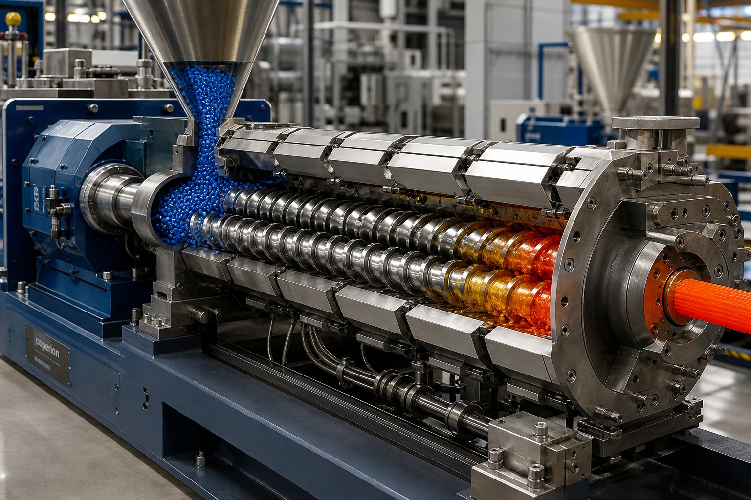
Imagine two screws sitting side by side inside a heated barrel, both spinning in the exact same direction. As they turn, polymer pellets are pulled forward, squeezed, melted, intensely mixed, and shaped into a uniform compound - all in a single continuous pass. That, in its simplest form, is what a co-rotating twin screw plastic extruder does.
A co-rotating twin screw plastic extruder is a polymer processing machine that uses two parallel, intermeshing screws rotating in the same direction within a heated barrel to convey, melt, mix, and shape plastic materials into homogeneous compounds.
What separates this machine from a standard single-screw extruder? The answer comes down to mixing capability. A single-screw design relies primarily on drag flow along one channel, which limits how thoroughly it can blend fillers, pigments, or reinforcements into a polymer matrix. A co-rotating twin screw extruder, by contrast, forces material through tightly intermeshing screw flights that continuously transfer it from one screw to the other. The result is dramatically superior distributive and dispersive mixing, modular screw design flexibility, and the ability to handle everything from glass-fiber-filled engineering plastics to delicate biopolymer blends.
This is precisely why the co-rotating configuration dominates modern plastics compounding. Its fully intermeshing geometry creates a self-wiping action where each screw continuously cleans the other, preventing material from stagnating in dead zones and degrading under prolonged heat exposure.
What Makes It Co-Rotating
The term "co-rotating" simply means both screws turn in the same rotational direction - both clockwise or both counterclockwise. Sounds straightforward, but the processing implications are significant.
When two intermeshing screws rotate the same way, material entering the flight of one screw gets pushed into the flight of the adjacent screw at the intermeshing zone. This creates a characteristic figure-eight flow path as the polymer travels downstream. You'll notice that the material doesn't just slide forward - it's repeatedly transferred between screws, folded over, and reoriented. Each transfer exposes fresh polymer surfaces to barrel heat and mechanical energy.
The self-wiping action is the real engineering advantage here. Because the flight tip of one screw closely sweeps the root of the other, there are virtually no stagnant pockets where heat-sensitive polymers could sit, overheat, and degrade. This makes a co-rotating twin screw extruder especially forgiving when processing thermally sensitive formulations or when switching between different color or material batches - residual material from the previous run gets wiped clean rather than accumulating in hidden corners.
Co-Rotating vs Counter-Rotating at a Glance
Engineers often ask: why not a counter-rotating twin screw extruder? Both designs use two screws, but they serve fundamentally different processing roles. Here's a quick comparison to clarify where each configuration fits best:
| Attribute | Co-Rotating Twin Screw Extruder | Counter-Rotating Twin Screw Extruder |
|---|---|---|
| Mixing Intensity | High - excellent dispersive and distributive mixing | Moderate - gentler shear profile |
| Self-Wiping Capability | Fully self-wiping at the intermeshing zone | Limited or no self-wiping action |
| Throughput Capacity | High - suited for large-volume compounding | Lower - constrained by inter-screw pressure |
| Pressure Generation | Moderate - typically requires a gear pump for high-pressure applications | High - strong positive conveying and pressure build-up |
| Typical Applications | Compounding, masterbatch, reactive extrusion, recycling | PVC profile extrusion, pipe extrusion, low-shear processing |
The takeaway? A co-rotating design excels whenever intensive mixing, high throughput, and formulation flexibility are the priorities. Counter-rotating machines earn their place in applications like rigid PVC extrusion, where strong pressure generation and gentler shear matter more than mixing intensity.
Understanding these foundational differences is only the starting point. The real performance of any twin-screw extruder depends on what happens inside the barrel - specifically, how polymer material transforms as it moves through distinct processing stages from feed throat to die head.
How the Three-Stage Twin Screw Extrusion Process Works
Drop a handful of polymer pellets into one end of a co-rotating twin screw extruder. Within seconds, those solid granules travel through a precisely engineered sequence of physical transformations - compressed, melted, intensively mixed, stripped of volatiles, and pressurized into a uniform melt stream ready for pelletizing or shaping. The entire journey happens across three distinct processing stages, and understanding each one is the difference between running a stable, optimized line and constantly chasing quality problems.
Feeding and Solids Conveying Stage
Everything starts at the feed throat. Gravimetric (loss-in-weight) or volumetric feeders meter raw material - whether pellets, powder, flakes, or a pre-blended dry mix - into the barrel opening at a controlled rate. Inside the barrel, large-pitch forward-conveying screw elements grab the incoming solids and transport them downstream. These elements feature deep flights and wide channels, maximizing free volume so that bulk material moves efficiently without compacting prematurely.
Why does feed consistency matter so much? Starve-feeding - delivering too little material relative to screw speed - leaves the screws under-filled, reducing residence time and potentially compromising mixing quality. Flood-feeding, on the other hand, overfills the intake zone and can cause material to back up into the feed throat or hopper, leading to bridging and erratic output. Most modern twin screw extrusion lines run in starve-fed mode by design, where the feeder - not the screw speed - controls throughput. This gives operators a powerful lever for tuning fill level independently of screw RPM.
For formulations requiring fillers or reinforcements like glass fiber, side stuffers introduce those downstream additives into the barrel at a later position. This prevents fragile fibers from excessive shear exposure in the early melting zone and allows the polymer to soften before filler incorporation begins.
Melting, Compression, and Intensive Mixing Stage
Here is where the extruder twin screw design truly earns its reputation. As solid material advances past the conveying zone, it encounters kneading blocks - stacked disc elements offset at specific angles that generate intense shear and friction. The polymer is squeezed through narrow gaps between the intermeshing kneading discs and the barrel wall, converting mechanical energy into heat. Combined with external barrel heaters set to target zone temperatures, this dual energy input rapidly melts the polymer.
Two fundamentally different types of mixing occur simultaneously in this stage:
- Dispersive mixing breaks down agglomerates - clusters of pigment particles, filler clumps, or undispersed additive lumps - by subjecting them to high shear stress that overcomes cohesive forces holding the agglomerate together.
- Distributive mixing spreads the now-dispersed components uniformly throughout the polymer matrix, ensuring homogeneous spatial distribution without necessarily applying additional shear.
The distinction matters more than many operators realize. A compound can have excellent dispersion - every pigment particle fully broken apart - yet still show streaks or inconsistencies if distributive mixing is insufficient. Conversely, gently redistributing poorly dispersed agglomerates just moves the problem around without solving it. The kneading block configuration - specifically whether elements are forward-advancing, neutral, or reverse-oriented - determines the balance between these two mixing modes.
Barrel zone temperatures in this stage work in concert with mechanical shear input. Setting temperatures too low forces the motor to do more work, increasing specific energy consumption and risking torque overloads. Setting them too high can degrade heat-sensitive polymers before mixing is complete. Experienced operators dial in a temperature profile that lets mechanical and thermal energy share the melting workload efficiently.
Melt Conveying and Devolatilization Stage
Once the polymer is fully molten and mixed, forward-conveying elements with progressively tighter pitch push the melt toward the die. But before the material exits the machine, most double screw extruder configurations include one or more vacuum venting ports along this final stage.
Devolatilization removes trapped moisture, residual monomers, dissolved gases, and other volatile contaminants from the melt. The process relies on exposing the polymer to a rapid pressure drop under vacuum. As industry experts note, a good rule of thumb is that each vent can reduce volatile concentration by roughly an order of magnitude - meaning a triple-vented machine can bring initial volatile levels down dramatically.
For effective venting, the screw section beneath the vent port must be only partially filled so that volatiles can escape to the vapor space above the melt rather than being trapped under pressure. Reverse-conveying elements or neutral kneading blocks positioned upstream of the vent create a melt seal - a fully filled section that isolates the vacuum zone from adjacent barrel sections. If this seal is poorly designed or operating conditions shift, molten polymer can flood back up into the vent opening, a common and costly problem.
After devolatilization, the final conveying elements build melt pressure to push material through a screen changer and die head. The pressure required depends on the die geometry, melt viscosity, and target throughput rate.
Mastering the interplay between feed rate, screw speed, barrel temperatures, and vent vacuum across all three stages is what separates consistent, high-quality output from a line plagued by surging, degradation, or poor compound uniformity.
Of course, how each stage performs depends entirely on which screw elements occupy each barrel zone - and that modular flexibility is the defining engineering advantage of the co-rotating platform. The specific element types available, how they interact, and the logic behind arranging them into an effective screw profile deserve their own detailed look.
Screw Element Types and Configuration Guide
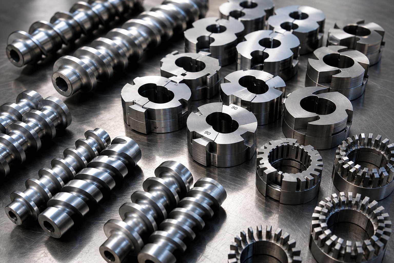
Picture a bare screw shaft - essentially a long, splined steel rod. On its own, it does nothing. The magic of a compounding twin screw extruder lies in what you slide onto that shaft: a carefully sequenced assembly of modular screw elements, each one engineered to perform a specific task at a specific point in the process. Swap a kneading block for a conveying element, change a stagger angle from 45 degrees to 90 degrees, and you fundamentally alter how the machine handles your formulation.
This modularity is the single biggest reason co-rotating platforms dominate plastics compounding. Unlike single-screw machines where the screw is one monolithic piece, a twin screw compounding extruder lets you reconfigure the processing profile for every new material - without buying a new screw. Getting that configuration right, however, requires understanding what each element type actually does.
Conveying Elements and Their Pitch Variations
Conveying elements are the workhorses of the screw profile. They look like traditional screw flights and serve one primary job: moving material downstream. But not all conveying elements behave the same way, and pitch selection is where operators gain real control.
Forward-conveying elements with a large pitch (high lead) grab bulk material aggressively, providing fast transport with minimal shear. You'll typically find these right at the feed throat, where the priority is pulling solids into the barrel and moving them efficiently toward the melting zone. The trade-off? High-lead elements keep the fill ratio low, which means material spends less time in that zone.
Shift to a small-pitch conveying element, and the dynamic changes. Tighter flights slow material down, increase fill level, and build pressure. These are ideal in the metering section near the die, where you need controlled pressure buildup to push melt through the screen changer and die head.
Reverse-conveying elements flip the script entirely. Their left-hand threads push material backward against the main flow direction, creating a localized dam of back-pressure. Why would you intentionally slow things down? Because reverse elements are essential for creating melt seals before vent ports, increasing residence time in mixing zones, and ensuring the barrel stays fully filled where you need it to be. A key rule of thumb: keep reverse elements shorter than one screw diameter to avoid dangerous pressure spikes and excessive shear strain.
Kneading Blocks and Mixing Elements
If conveying elements are the workhorses, kneading blocks are the specialists. These are stacks of elliptical discs offset at specific angles along the shaft, and their orientation determines everything about how aggressively they process the polymer.
Three orientations define kneading block behavior:
- Forward kneading blocks - discs staggered in the conveying direction. They provide moderate shear while still advancing material downstream. Think of these as your everyday melting elements, balancing energy input with throughput.
- Neutral kneading blocks (90-degree stagger) - discs offset at right angles, producing high shear with zero forward conveying effect. Material sits in this zone longer, absorbing maximum mechanical energy. These elements are aggressive, and as NC State Extension research notes, neutral kneading elements increase residence time because they only impart energy to the product without pushing it forward.
- Reverse kneading blocks - discs staggered opposite to the conveying direction. They push material backward, creating the strongest restriction and maximum shear intensity. Use these sparingly and strategically - they're powerful but can cause torque spikes if overused.
The stagger angle between adjacent discs fine-tunes the intensity within each orientation:
- 30 degrees - mild mixing, gentle energy input
- 45 degrees - balanced mixing, the most common general-purpose choice
- 60 degrees - strong dispersive mixing for breaking apart tough agglomerates
- 90 degrees - maximum shear, no conveying action
Beyond kneading blocks, specialized mixing elements handle situations where you need distributive mixing without pounding the material with excessive shear. Toothed mixing elements (TME) divide and recombine the melt stream repeatedly, spreading additives and pigments evenly without significant mechanical stress - ideal for color masterbatch or heat-sensitive formulations. Cam-type (ZME) elements generate elongational flow rather than pure shear, improving both dispersion and distribution simultaneously. For compounds with long glass fibers or biodegradable polymers that degrade under high shear, these gentler alternatives protect material integrity while still achieving homogeneity.
| Element Type | Primary Function | Typical Screw Position | Processing Effect |
|---|---|---|---|
| High-lead conveying | Fast material transport | Feed zone | High throughput, low fill ratio, minimal shear |
| Low-lead conveying | Pressure buildup | Metering / pre-die zone | Increased fill level, controlled pressure development |
| Reverse conveying | Back-pressure / melt seal | Before vent ports, after mixing zones | Flow restriction, increased residence time |
| Forward kneading block (30-45 degrees) | Melting, moderate mixing | Melting zone | Balanced shear with forward conveyance |
| Neutral kneading block (90 degrees) | Intensive dispersive mixing | Primary mixing zone | Maximum shear, no forward conveying |
| Reverse kneading block | High-shear restriction | After melting zone, before venting | Strong back-pressure, maximum energy input |
| Toothed mixing element (TME) | Distributive mixing | Homogenization zone | Even additive distribution, low shear |
| Cam-type element (ZME) | Elongational mixing | Homogenization zone | Combined dispersive and distributive mixing |
Building a Screw Profile for Plastic Compounding
Knowing what each element does is one thing. Arranging them into a coherent screw profile is where science meets practical experience.
Every compounding extruder screw profile follows a general logic, even though specific layouts vary by formulation:
- Feed zone: Start with high-lead conveying elements to grab incoming material and transport it efficiently. If side stuffers introduce fillers downstream, a second set of large-pitch conveyors appears at that barrel position.
- Melting zone: Transition to kneading blocks - typically forward-staggered at 45 or 60 degrees - to convert mechanical energy into heat and melt the polymer. A short reverse kneading block or reverse conveying element at the end of this zone creates back-pressure that ensures full melting before material advances.
- Homogenization zone: Position distributive mixing elements like TME or ZME here to blend additives, pigments, or fillers uniformly throughout the melt without adding unnecessary shear stress.
- Venting zone: Place reverse elements or a narrow kneading block upstream of each vacuum vent to create a melt seal. Follow with large-pitch conveying elements under the vent port itself, keeping the barrel partially filled so volatiles can escape freely.
- Metering zone: Finish with progressively lower-pitch conveying elements that build smooth, consistent pressure to push the melt through the die.
Getting this sequence wrong has real consequences. Place kneading blocks too early, before material has softened, and you risk torque overloads that trip the motor. Skip the melt seal before a vent port, and molten polymer floods up into the vacuum system. Use too many high-shear elements on a fiber-reinforced compound, and you'll shatter every glass strand before it reaches the die.
The beauty of the modular system is that corrections don't require a new screw - just rearranging elements on the existing shaft. Experienced processors often keep a library of proven screw profiles for their most common formulations and fine-tune from there when a new compound arrives.
A well-designed screw profile will efficiently convey, melt, mix, devolatilize, and pressurize material - but only when the right elements appear at the right positions along the barrel.
Still, even a perfectly configured screw profile can underperform if the machine's fundamental specifications - barrel length and available torque - don't match the complexity of the application. Two critical parameters that deserve closer attention are L/D ratio and torque density, and they influence every decision about screw layout.
Understanding L/D Ratio and Torque Density
You can assemble the perfect screw profile, dial in ideal barrel temperatures, and still underperform - if the machine itself doesn't have enough barrel length or gearbox muscle for the job. Two specifications sit at the heart of every equipment decision for twin screw extruders, yet most data sheets list them without explaining what they actually mean for your process: L/D ratio and torque density.
What L/D Ratio Means for Plastics Processing
L/D ratio is simply the total barrel length divided by the screw diameter. A machine with 60 mm screws and a 2,400 mm barrel has a 40:1 L/D ratio. Straightforward math - but the processing implications run deep.
Think of L/D ratio as your real estate budget. Every unit operation you need - feeding, melting, mixing, filler incorporation, devolatilization, pressure buildup - requires barrel space. More operations demand more zones, and more zones demand a longer barrel relative to screw diameter.
Common L/D ratios for twin-screw extruders range from roughly 32:1 to 52:1, and here's what each range buys you in practice:
- 32:1 to 36:1 - suited for simpler compounding tasks with a single feed point, one mixing stage, and minimal venting. If you're blending a straightforward polymer with a small percentage of additive, this length is often sufficient.
- 40:1 to 44:1 - the most popular general-purpose range. It provides enough barrel length for a primary melting zone, a downstream side-stuffer port for filler addition, one or two vacuum vents, and a metering section. Most color masterbatch and standard filled compound operations fall here.
- 48:1 to 52:1 - reserved for the most demanding applications: reactive extrusion requiring extended residence time, highly filled compounds needing multiple feed points, multistage devolatilization with sequential vacuum ports, or processes combining several additive introduction steps in a single pass.
The trade-off? Longer barrels increase capital cost, require a larger factory footprint, and demand more heating and cooling capacity. Specifying a 52:1 machine for a process that only needs 36:1 wastes money and floor space. Conversely, cramming too many unit operations into a short barrel forces compromises in mixing quality, vent efficiency, or both.
Torque Density and Why It Matters
If L/D ratio determines how much processing space you have, torque density determines how much mechanical energy you can deliver within that space. Expressed in Nm/cm cubed, torque density measures the gearbox's torque capacity relative to the screw's cross-sectional volume. It's the single most telling specification for comparing one double screw extruder machine to another.
Why should you care? Imagine processing a high-viscosity, glass-fiber-filled polyamide. The screws have to overcome enormous resistance as they shear through a thick, abrasive melt. A low-torque machine hits its gearbox limit early, forcing operators to either reduce feed rate - cutting throughput - or increase screw speed to compensate. Higher screw speed means higher shear, which degrades the polymer, breaks fibers, and raises melt temperature beyond target.
A high-torque-density machine flips that equation. It delivers the required energy at lower screw speeds, keeping shear gentle and melt temperature controlled while maintaining full production throughput. The result is better compound quality, longer fiber lengths in the finished pellet, and reduced specific energy consumption per kilogram of output.
How do real-world numbers compare? Industry data shows that state-of-the-art twin screw extruders now reach torque densities of 18 Nm/cm cubed - a roughly 30% jump over previous-generation machines. Standard-class equipment typically operates in the 5 to 10 Nm/cm cubed range, while high-torque platforms exceed 10 Nm/cm cubed. That gap is not just a spec-sheet number; it directly translates into what materials you can process and how fast you can run them.
One practical guideline worth remembering: operate at roughly 80% of the gearbox's continuous torque rating and 80% of maximum screw speed. This margin absorbs the inevitable torque spikes during cold starts - which can exceed steady-state loads by 20 to 40% - without risking gearbox damage or unplanned shutdowns.
Matching L/D ratio and torque density to the target application prevents both under-processing (insufficient mixing, poor devolatilization) and over-processing (excessive shear, thermal degradation) of plastic compounds - and it's the first specification decision that every other equipment choice depends on.
These two parameters define the machine's capability envelope, but capability alone doesn't determine success. The real question most processors need answered is more specific: which plastics and polymer formulations actually benefit most from a co-rotating design, and what processing characteristics make it the preferred platform for each material type?
Best Plastics and Materials for Co-Rotating Extrusion
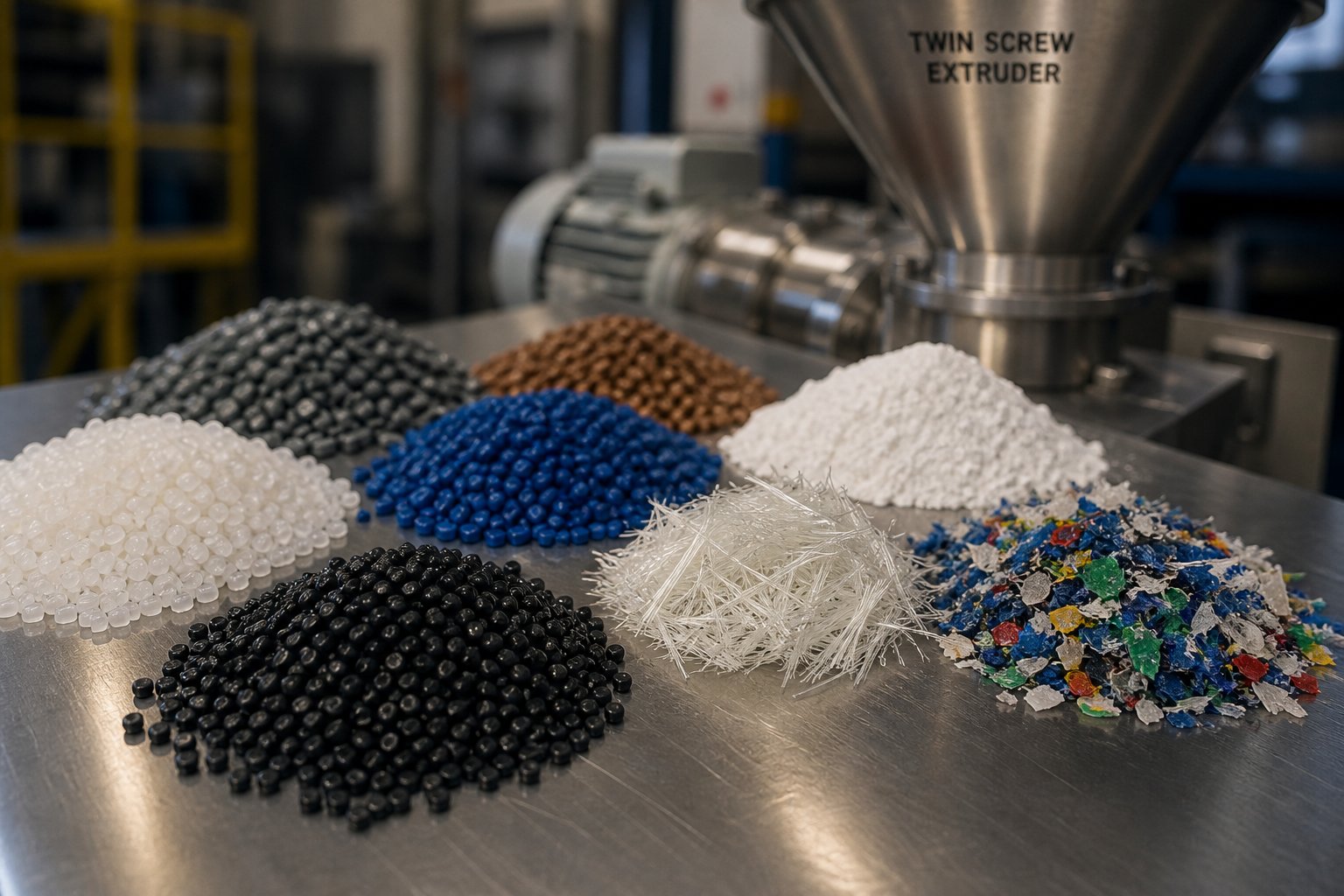
A machine's specs tell you what it can do. The materials you run through it tell you what it should do. Every polymer family brings its own melting behavior, viscosity profile, filler loading challenge, and thermal sensitivity to the barrel - and the co-rotating platform handles a remarkably wide range of them. But "wide range" doesn't mean "everything equally well." Some material categories genuinely thrive on the high-shear, self-wiping, modular processing environment that a twin screw plastic extruder provides, while others are better served by simpler equipment. Here's where the co-rotating design delivers its clearest advantages.
Engineering Plastics and Filled Compounds
When you compound engineering resins like PA (nylon), PBT, PC, PPO, or POM - especially with glass fiber, mineral fillers, or carbon fiber reinforcements - the co-rotating extruder is the default choice for good reason. These high-performance polymers demand precise thermal control because many of them have narrow processing windows. POM, for example, has a melting point dangerously close to its degradation temperature, leaving almost no margin for error. PC is tough and transparent but cracks under stress if exposed to solvents during processing. PA absorbs moisture readily, which means the extruder's devolatilization capability becomes essential for removing water before it causes hydrolytic degradation in the melt.
Filler incorporation raises the stakes further. Imagine trying to uniformly distribute 30% glass fiber throughout a PA66 matrix. Each fiber bundle must be wetted out - meaning the polymer must fully coat every individual filament - without excessive shear that snaps the fibers into useless fragments. The intermeshing zone of a plastic twin screw extruder generates exactly the kind of dispersive mixing needed to break apart fiber bundles and the distributive mixing needed to spread them evenly. Side stuffers introduce the glass downstream, after the polymer is already molten, protecting fiber length from the aggressive kneading blocks in the melting zone.
Mineral fillers like talc, calcium carbonate, and wollastonite present a different challenge. These particles tend to form agglomerates that resist breakup. The high shear stress available in the kneading block sections of a co-rotating machine overcomes the cohesive forces holding those agglomerates together, delivering the uniform particle distribution that end-product performance depends on.
Masterbatch, Color, and Additive Concentrates
Walk into any masterbatch production facility and you'll find twin screw extruder plastic compounding lines running around the clock. Color concentrates demand something that might seem contradictory: intense enough mixing to fully disperse pigment particles down to their primary grain size, yet gentle enough processing to avoid degrading the carrier resin or shifting color values.
This is where the modular screw design pays dividends. Masterbatch producers configure kneading blocks for aggressive dispersive mixing right where pigment agglomerates need breaking apart, then transition to toothed or cam-type distributive elements downstream that spread the dispersed pigment uniformly without adding excessive thermal history. The result is a concentrate that delivers consistent color when letdown into the final product at ratios as low as 1-3%.
Additive masterbatch follows similar logic. UV stabilizers, flame retardants, antioxidants, and anti-static agents each have specific particle sizes, melting behaviors, and thermal sensitivities. Flame retardants, in particular, can be corrosive and abrasive, demanding not just precise mixing but also careful metallurgy selection for the screw elements and barrel liners that contact them. The co-rotating platform's flexibility - adjustable screw profiles, multiple feeding positions, and precise temperature zoning - lets manufacturers tailor the process to each additive package rather than forcing a one-size-fits-all approach.
Recycled Plastics and Bioplastics Processing
Here is where the twin screw extruder plastic processing capability becomes increasingly critical. Post-consumer and post-industrial recycled streams are inherently inconsistent - mixed polymer types, variable melt flow indices, residual contaminants, moisture, and trapped odors. A single-screw machine simply can't homogenize these feedstocks effectively.
A co-rotating twin screw plastic extruder tackles recycled materials on multiple fronts simultaneously. The kneading sections melt and blend mixed polymers into a more homogeneous melt. Vacuum venting ports strip out moisture, volatile organic compounds, and odor-causing substances - often requiring two or three sequential vent stages to bring contaminant levels down to acceptable thresholds. Screen changers positioned downstream catch solid contaminants before they reach the pelletizer.
Bioplastics add yet another processing dimension. Materials like PLA, PHA, and starch-based blends are thermally sensitive and often hygroscopic. PLA, for instance, degrades rapidly at elevated temperatures, so residence time must be kept short and barrel temperatures carefully controlled. The co-rotating design's efficient conveying and self-wiping action minimize the time any material spends in the barrel, and the ability to run at high screw speeds with low fill levels reduces thermal exposure. Starch-based compounds require thorough gelatinization and mixing with plasticizers, a task that benefits directly from the intense kneading and distributive mixing zones available in a modular screw profile.
To pull all of this together, here are the key material categories and the specific processing characteristics that make a co-rotating extruder the preferred platform for each:
- Engineering plastics (PA, PBT, PC, PPO, POM): Narrow thermal processing windows, need for precise temperature control, devolatilization of moisture, and high-shear filler incorporation with uniform distribution.
- Glass-fiber and mineral-filled compounds: Downstream filler feeding via side stuffers, dispersive mixing to break agglomerates, distributive mixing for homogeneous filler distribution, and fiber-length preservation through controlled shear.
- Color and additive masterbatch: Intense pigment dispersion to primary particle size, gentle distributive mixing for carrier resin integrity, multiple feed points for staged additive introduction, and fast color changeover enabled by self-wiping geometry.
- Recycled polymers (post-consumer and post-industrial): Homogenization of inconsistent feedstock, multi-stage vacuum devolatilization for moisture and odor removal, melt filtration compatibility, and tolerance for variable bulk density and melt flow properties.
- Bioplastics (PLA, PHA, starch blends): Low residence time to prevent thermal degradation, precise barrel temperature profiles, efficient plasticizer incorporation, and gentle yet thorough mixing without excessive shear.
Matching the right material to the right machine configuration is only part of the equation, though. A co-rotating extruder never operates in isolation - it sits at the center of a complete processing line, flanked by feeding systems upstream and pelletizing equipment downstream. How well those surrounding systems integrate with the extruder determines whether all the mixing precision you've achieved inside the barrel actually translates into consistent, sellable pellets at the end of the line.
Downstream Equipment and Complete Line Integration
Here's something that catches many first-time compounders off guard: you can specify the perfect twin-screw extruder machine, configure an ideal screw profile, and dial in flawless barrel temperatures - and still produce unusable pellets. Why? Because the extruder is only one piece of a much larger system. What happens before material enters the barrel and after it exits the die determines whether all that precision mixing actually reaches the customer as a consistent, high-quality product.
Think of a compounding line as a chain. The extruder is the strongest link, but the chain breaks at its weakest point - whether that's an inaccurate feeder starving the intake, a poorly matched pelletizer chopping uneven granules, or a cooling system that can't keep up with throughput. Understanding the full equipment chain isn't optional; it's essential.
Upstream Feeding and Material Handling
Every compounding operation lives or dies by feed accuracy. If the wrong ratio of polymer to filler enters the barrel, no amount of downstream mixing can fix the formulation error - you've already produced off-spec material.
Two primary feeder types handle the job:
- Volumetric feeders deliver material at a set volume per unit time using an auger or vibratory tray. They're simpler and less expensive, but they can't compensate for variations in bulk density. If your raw material's bulk density fluctuates - common with regrind flakes or powdered additives - volumetric feeders introduce mass flow inconsistencies.
- Gravimetric (loss-in-weight) feeders continuously weigh the hopper and adjust screw speed in real time to maintain a target mass flow rate. They cost more, but they deliver the precision that demanding formulations require. For operations producing engineering compounds with tight property specifications, gravimetric feeding is the standard.
Beyond the main feed throat, most compounding lines incorporate additional material introduction points along the barrel. Side stuffers - smaller twin-screw feeders mounted at a 90-degree angle to the main barrel - push fillers like glass fiber, talc, or calcium carbonate into the melt downstream of the primary melting zone. This staged introduction protects fragile reinforcements from the high-shear kneading blocks and ensures the carrier polymer is already molten when filler arrives.
Liquid injection systems handle oils, plasticizers, coupling agents, or liquid color additives. These systems use precision metering pumps to inject fluids directly into the melt stream through barrel ports, typically positioned in a partially filled section where the liquid can be absorbed and distributed without causing pressure instability. Getting the injection point wrong - placing it in a fully pressurized zone, for instance - leads to pump cavitation, erratic dosing, and inconsistent compound properties.
One detail worth emphasizing: feeder accuracy directly impacts cost control. A 1% overfeeding error on an expensive additive across a 24-hour production run adds up to significant raw material waste. Conversely, underfeeding a flame retardant by even a small margin can push the final compound below its UL94 flammability rating, resulting in rejected lots and potential safety liability.
Downstream Equipment for Pelletizing and Finishing
Once the melt exits the die, it needs to be cooled, solidified, and cut into pellets - and the method you choose shapes pellet geometry, surface quality, throughput capacity, and even which compounds you can run.
Before pelletizing begins, the melt typically passes through a screen changer for melt filtration. Screen changers hold one or more fine mesh screens that catch solid contaminants, gels, and undispersed agglomerates. Hydraulic slide-plate or continuous-belt screen changers allow filter changes without stopping the line - critical for high-throughput operations or recycled feedstock processing where contaminant loads are unpredictable.
The die head itself comes in two fundamental configurations. Strand dies extrude multiple spaghetti-like strands that are cooled and then chopped. Underwater dies push melt through a perforated plate where rotating blades cut pellets immediately at the die face, with water carrying them away for cooling simultaneously. Each die type pairs with a specific pelletizing method.
Here's how the three main pelletizing approaches compare across the criteria that matter most to compounders:
| Criteria | Strand Cutting | Underwater Pelletizing | Water-Ring Pelletizing |
|---|---|---|---|
| Pellet Shape | Cylindrical | Spherical to lenticular | Spherical to slightly irregular |
| Throughput Range | Low to moderate (up to ~2,000 kg/hr typical) | Moderate to very high (up to 10,000+ kg/hr) | Low to moderate (up to ~1,500 kg/hr typical) |
| Suitability for Soft/Sticky Compounds | Poor - strands stick together and are difficult to convey | Excellent - immediate water quench prevents agglomeration | Good - water contact minimizes sticking |
| Capital Cost | Lowest | Highest | Moderate |
| Operator Skill Required | Moderate - requires manual strand threading on startup | Low - largely automated once running | Low to moderate |
| Best Suited For | Rigid engineering compounds, small-batch production, laboratory scale extruder trials | High-volume production, soft elastomers, adhesive compounds | Mid-volume production, general-purpose compounding |
Strand pelletizing remains popular for its simplicity and low capital investment. The extruded strands drop into a water bath for cooling, travel across an air-wipe conveyor to remove surface moisture, and feed into a strand pelletizer that chops them into uniform cylinders. It works well for rigid, non-tacky compounds - filled nylons, polycarbonate blends, PBT - where strands maintain their shape through the cooling trough. For softer materials like TPE or EVA, though, strands tend to deform, stick together, or break before reaching the cutter.
Underwater pelletizing solves the soft-compound problem entirely. Pellets are cut at the die face and immediately quenched, so they never have the chance to deform or agglomerate. The trade-off is higher equipment cost and more complex startup procedures. Large-scale compounders and every major twin-screw extruder manufacturer offering turnkey lines typically recommend underwater systems for throughputs above 2,000 kg/hr or whenever processing tacky, low-viscosity materials.
Water-ring pelletizing sits between the two. Pellets are cut at the die face and swept into a water ring for cooling - simpler than full underwater systems but offering better handling of soft compounds than strand cutting. It's a practical choice for mid-volume operations that need pellet shape consistency without the capital outlay of underwater equipment.
Controls and Process Monitoring
A modern co-rotating compounding line isn't just mechanical hardware - it's a data-generating system. PLC-based or SCADA-integrated control platforms tie the entire line together, from feeders to pelletizer, monitoring dozens of process variables in real time.
The critical parameters that operators and control systems track include:
- Melt temperature - measured at the die or at intermediate barrel positions. Deviations signal changes in shear input, barrel heating performance, or material viscosity shifts.
- Melt pressure - monitored at the die head and before screen changers. Rising pressure indicates screen blockage or increased melt viscosity; sudden drops suggest material starvation or die lip fouling.
- Motor load (torque) - expressed as a percentage of maximum. Trending upward torque at constant throughput and RPM is one of the earliest indicators of screw or barrel wear, changing feedstock properties, or barrel temperature profile issues.
- Throughput rate - the combined output of all feeders, cross-checked against pelletizer output to verify mass balance and detect losses.
Advanced lines go further, incorporating inline rheometers for real-time viscosity measurement, near-infrared spectroscopy for composition verification, and automated feedback loops that adjust feeder rates or screw speed to maintain target parameters without operator intervention. Even smaller-scale or laboratory scale extruder setups increasingly offer data-logging capabilities that let development teams analyze process trends and scale formulations up to production equipment with documented parameter sets.
The practical takeaway? Selecting the right downstream equipment is every bit as important as specifying the extruder itself. A perfectly mixed melt means nothing if the pelletizer produces inconsistent granules, the cooling system introduces moisture, or the control system can't flag a drifting process variable before it becomes a quality defect. Treat the entire line as one integrated system - because that's exactly how it behaves in production.
All of this equipment, however, operates in a demanding environment. Abrasive fillers grind against barrel walls. Corrosive additives attack metal surfaces. Screw elements wear down flight by flight. The long-term performance and economics of a compounding line hinge on how well you manage wear - and that starts with understanding the metallurgy choices and maintenance strategies that keep your barrel and screws in spec.
Maintenance, Wear, and Barrel Selection for Longevity
Abrasive fillers don't care how well your screw profile is designed. Glass fiber, calcium carbonate, talc, carbon fiber - these materials grind against metal surfaces every second the machine runs. Add corrosive additives like halogenated flame retardants or certain organic pigments to the mix, and you're attacking your twin screw barrel and screw elements through both mechanical abrasion and chemical erosion simultaneously. It's a relentless process, and ignoring it doesn't make it slower - it just makes the consequences more expensive.
Here's what many engineers overlook: wear doesn't announce itself with a sudden failure. It creeps in gradually. Clearances between screw flights and barrel walls widen by fractions of a millimeter over weeks and months. Mixing efficiency quietly declines. Melt temperature drifts upward because the material is no longer being sheared efficiently - it's slipping through enlarged gaps instead. By the time operators notice declining compound properties, the twin screw and barrel may already be well past the point where performance can be recovered without component replacement.
Understanding the metallurgy options for both screw elements and extrusion barrels - and knowing when to replace them - is what separates operations that run profitably from those constantly fighting quality problems and unplanned downtime.
Screw Element Metallurgy and Wear Protection
Not all screw elements are created equal, and the right metallurgy choice depends entirely on what you're processing. Selecting an element material that's overqualified wastes money. Selecting one that's underqualified wastes far more - in premature replacement costs, off-spec product, and lost production hours.
The metallurgy options fall into a clear hierarchy of wear resistance and cost:
Nitrided steel is the baseline. Elements made from steel like 38CrMoAlA undergo gas nitriding, where nitrogen atoms diffuse into the surface layer at around 500-570 degrees Celsius, forming a hard nitride case. The result is a cost-effective element with good basic wear resistance that works well for standard compounding operations - unfilled polymers, lightly loaded mineral compounds, or color masterbatch with non-abrasive pigments. If your formulation doesn't involve aggressive fillers or corrosive chemistry, nitrided steel delivers acceptable service life at the lowest element cost.
Tool steel and high-speed steel (HSS) step up when formulations include moderate filler loadings or mildly abrasive additives. Grades like Cr12MoV or M2 (W6Mo5Cr4V2) contain higher concentrations of carbon, chromium, tungsten, molybdenum, and vanadium. After quenching and tempering, they achieve substantially higher matrix hardness and retain that hardness at elevated processing temperatures. For compounds with 10-20% calcium carbonate or talc, tool steel elements often hit the sweet spot of performance versus cost.
Powder metallurgy high-speed steel (PM-HIP) is where serious abrasion resistance begins. These elements are manufactured by atomizing pre-alloyed metal powder and consolidating it under hot isostatic pressing. The resulting microstructure is remarkably uniform - no segregation of alloying elements, no coarse carbide clusters that create weak points. PM-HIP elements resist the punishing wear generated by high glass fiber loadings (30%+), heavily filled mineral compounds, and carbon fiber reinforcements. They cost significantly more than nitrided or conventional tool steel, but their extended service life typically delivers a lower cost-per-kilogram of compound produced.
High-wear-resistance HIP alloy steels - grades like WR5, WR13, WR14, and CPM series alloys - push wear resistance even further. These materials incorporate ultra-high levels of strong carbide-forming elements such as vanadium and tungsten, producing dense populations of extremely hard carbide particles (like vanadium carbide) throughout the matrix. They're engineered for the most severe operating conditions: highly filled formulations with 50%+ mineral content, abrasive recycled feedstocks contaminated with sand or metallic particles, and processes where element replacement intervals need to be maximized.
For processors handling corrosive chemistry - fluoropolymers that release hydrofluoric acid, PVC that liberates hydrochloric acid, or flame retardant packages containing halogenated compounds - nickel-based corrosion-resistant alloys offer protection that no carbon or tool steel can match. These alloys form stable passivation layers that resist acid attack, preserving element geometry and surface finish even under aggressive chemical exposure.
Beyond base material selection, surface treatments add another layer of protection. Tungsten carbide coatings applied via HVOF (high-velocity oxygen fuel) spraying create an extremely hard wear surface on top of a tough substrate, delivering both abrasion resistance and impact toughness. This approach works particularly well for kneading block tips and screw flight crests - the high-wear contact points where clearance loss happens fastest. As industry case studies demonstrate, combining the right base metallurgy with targeted surface hardening can extend equipment lifespan by 30% or more while improving production efficiency.
Barrel Liner Materials and Replacement Strategy
Screw elements get most of the attention during maintenance planning, but the barrel wears too - and worn extrusion barrels create problems that are harder to detect and more expensive to ignore.
Imagine the barrel bore as the outer boundary of your mixing system. Every kneading block, every conveying flight, every reverse element generates shear and pressure against that inner wall. When the barrel is new, the tight clearance between screw tip and bore wall forces material through narrow gaps, creating the intense mixing action the process depends on. As that clearance widens from wear, material increasingly bypasses the high-shear zones. The result? Declining mixing efficiency, rising melt temperatures (because the motor works harder to compensate), and - eventually - compound properties that drift out of specification.
Barrel construction options parallel the screw element metallurgy hierarchy:
Nitrided steel liners provide baseline abrasion resistance for standard processing applications. The same gas nitriding process used on screw elements hardens the bore surface, creating a functional liner at the lowest cost. For operations running unfilled or lightly filled polymers without corrosive additives, nitrided barrels deliver reasonable service life.
Bimetallic liners are the workhorse solution for abrasive and corrosive formulations. These barrels feature a centrifugally cast or hot isostatically pressed alloy liner bonded to a structural steel outer shell. Iron-based bimetallic alloys offer excellent abrasion resistance for glass-fiber and mineral-filled compounds. Nickel-based alloys - such as the nickel-rich boron alloys with molybdenum, boride, and carbide components - provide both abrasion and corrosion resistance, making them essential for processing PVC, fluoropolymers, or formulations with halogenated flame retardants.
Fully lined barrels with tungsten-carbide-based alloys represent the highest tier of wear protection. These are specified for the most extreme environments - ultra-high filler loadings, aggressive recycled feedstocks, or continuous operations where unplanned shutdowns for barrel replacement carry enormous production cost penalties.
One factor that separates proactive operations from reactive ones is replacement planning. Worn barrels can't be repaired on the machine - they must be removed, relined or replaced, and reinstalled. That means sourcing the right twin screw barrel before the old one reaches end-of-life, not after. Having a reliable supply chain for replacement or custom-engineered barrels is the difference between a planned weekend swap and weeks of unplanned downtime waiting for components. Specialists like NANHAIYA offer parallel twin screw barrels engineered for stable conveying, mixing, and high-wear plastics processing, serving compounding producers, masterbatch manufacturers, recycling plants, and pelletizing operations that can't afford to wait when wear components reach their limits.
Thermal expansion matching is another detail that experienced engineers factor into barrel selection. When barrel and screw materials have significantly different coefficients of thermal expansion, processing at high temperatures - think PC at 240 degrees Celsius, PA at 280 degrees, or PPS at 290 degrees - can cause clearance gaps to shift unpredictably. In worst-case scenarios, mismatched thermal expansion leads to seizing, where metal-to-metal contact between screw and barrel causes thread damage and accelerated wear. Selecting barrel liner and screw element materials with compatible thermal expansion properties - and maintaining clearances around 1/1000 of the barrel diameter - prevents this costly failure mode.
So how do you know when your barrel or screw elements have crossed the line from "wearing" to "worn out"? The signs are consistent across virtually every co-rotating twin screw plastic extruder operation:
- Increased motor load at constant throughput and RPM - the motor works harder to push material through widened clearances and compensate for reduced conveying efficiency.
- Declining output quality - undispersed pigment specks, inconsistent filler distribution, lower tensile or impact strength in the final compound, or failing quality control tests that previously passed without issue.
- Visible wear marks - scoring, grooves, or material buildup on screw element surfaces; bore diameter measurements exceeding manufacturer tolerances during scheduled inspections.
- Inconsistent melt temperature - rising or fluctuating melt temperature readings at the die, even when barrel zone set points and screw speed remain unchanged, indicating that mechanical energy input has shifted due to geometry changes.
- Rising specific energy consumption - more kilowatt-hours required per kilogram of output, signaling that the machine is working less efficiently because worn components can no longer transfer energy to the material effectively.
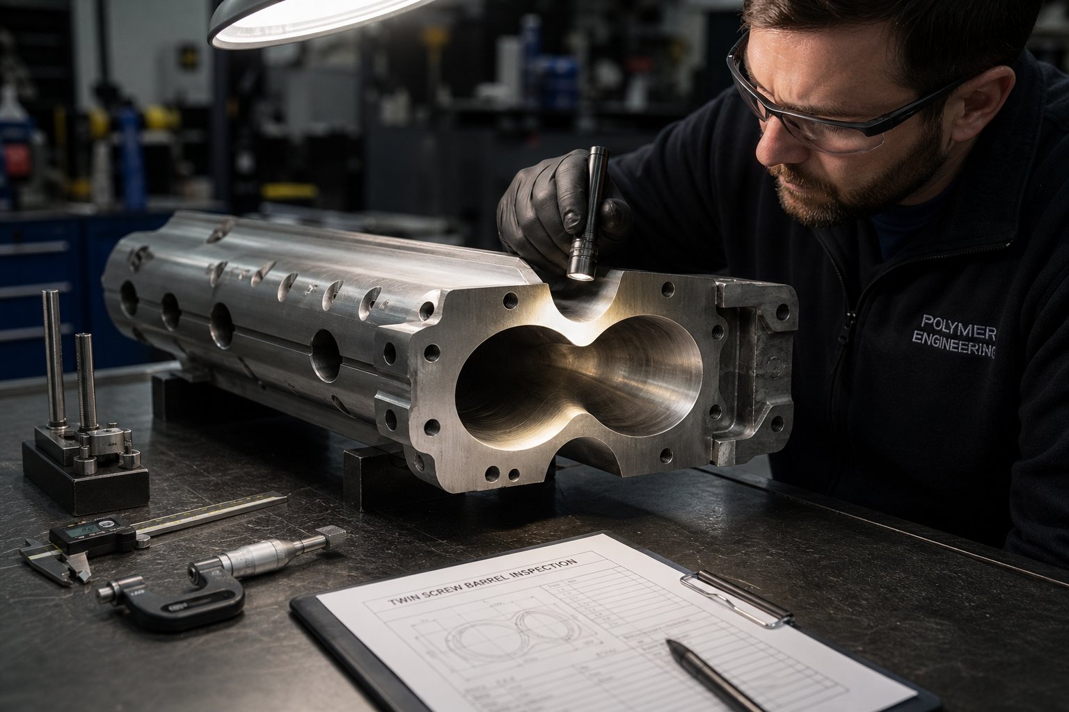
The bottom line? Regular inspection and measurement of both twin screw and barrel clearances should be part of every preventive maintenance schedule - not just for the four primary high-wear zones (feed zone, filler introduction zone, mid-barrel deflection area, and discharge zone) but across the full barrel length. Track wear trends over time, establish replacement thresholds based on compound quality requirements, and source your critical spare components before you need them - not after the line goes down.
Metallurgy and maintenance keep the machine running. But even with perfect components in perfect condition, operators still encounter process problems that have nothing to do with wear - surging output, flooded vents, torque overloads, poor dispersion. Diagnosing and correcting these operational issues quickly is what keeps a compounding line productive day after day.
Troubleshooting Common Co-Rotating Extrusion Problems
Your barrel metallurgy is right, your screw elements are fresh, your preventive maintenance schedule is up to date - and the line is still giving you trouble. Maybe the pelletizer output is pulsing. Maybe polymer is oozing out of a vent port. Maybe the motor keeps tripping on torque overload during a formulation you've run a hundred times before.
Welcome to the reality of twin screw extrusion troubleshooting. Most problems don't stem from worn hardware. They stem from process imbalances - a mismatch between feed rate, screw speed, temperature profile, screw configuration, or all four at once. The challenge is figuring out which variable shifted, and why.
A useful first step is determining whether the issue is chronic or transient. If a specific formulation has always run poorly - consistent strand breakage, persistent black specks, ongoing property degradation - the root cause likely sits in the screw design or fundamental process parameters. That's a chronic issue requiring a major intervention. But if a formulation that ran perfectly last week suddenly goes off the rails, you're chasing a transient problem: something changed overnight, and your job is to find what.
Here are the most common operational problems, what causes them, and how to fix them.
Surging and Output Inconsistency
Surging shows up as a rhythmic pulsation in extrudate output - you'll see it as fluctuating strand diameter at the die, inconsistent pellet size, or oscillating melt pressure readings on the control panel. It's one of the most frustrating problems because the line looks like it's running, but the product is subtly off-spec with every cycle.
The causes fall into four categories:
- Inconsistent feeding: A loss-in-weight feeder that's out of calibration, a hopper with material bridging, or a volumetric feeder struggling with inconsistent bulk density will deliver surging material flow to the screws. The extruder faithfully reproduces every feed fluctuation as an output fluctuation. Check feeder calibration first - always. As compounding diagnostics experts note, loss-in-weight feeders are often unfairly blamed for sudden failures, but hardware mismatches - like using the wrong feeder screw for a specific powder or pellet - can force the system to run at erratic speeds to maintain its setpoint.
- Partially blocked screen changers: As the melt filter accumulates contaminants, flow resistance increases unevenly. The extruder builds pressure until material forces through, then pressure drops - creating a sawtooth pattern in output. If you see rising die pressure trending alongside surging output, bump the screen changer to a fresh screen and confirm whether the problem disappears.
- Incorrect screw element configuration: Worn conveying elements in the pressure-building zone lose their ability to push material forward consistently, causing the melt to "pulse" rather than flow smoothly. This is the chronic variant of surging - it doesn't appear overnight, but develops gradually as clearances widen over weeks or months of operation. Measuring screw element diameters against original specifications reveals whether element replacement is overdue.
- Insufficient melt seal before vent ports: If the reverse elements or restrictive kneading blocks upstream of a vacuum vent don't create a proper melt seal, the partially filled vent zone can allow pressure fluctuations to propagate backward and forward through the barrel, disrupting steady-state flow.
The corrective logic is sequential: verify feed stability first, check downstream restrictions second, inspect screw elements third, and evaluate screw profile design last. Jumping straight to screw reconfiguration before ruling out a clogged screen or miscalibrated feeder wastes hours of downtime chasing the wrong cause.
Vent Flooding and Poor Devolatilization
Few problems are messier - or more disruptive to production - than molten polymer climbing out of a vacuum vent port. Vent flooding isn't just a cleanup headache; it signals a fundamental breakdown in the balance between forward conveying capability, gas expansion volume, and downstream restriction. If the problem isn't corrected, it leads to poor devolatilization, porous pellets, strand breakage at the pelletizer, and - in severe cases - damage to the vacuum system itself.
The devolatilization zone is designed to run partially filled. Only when the screw channel isn't completely packed can a free surface form, allowing trapped moisture and volatiles to escape the melt and be pulled away by vacuum. Anything that disrupts that partially filled condition sends melt up through the only available exit: the vent opening.
Four core factors drive vent flooding:
- Excessive fill level: Feeding more material than the screw can convey downstream causes localized overfilling directly under the vent. The fix is straightforward - reduce feed rate slightly or increase screw RPM to clear out the excess material and lower the fill factor in the vent zone.
- Insufficient melt seal from restrictive elements: Reverse kneading blocks or left-handed screw flights placed upstream of the vent create the pressure dam that forces volatiles out of the melt. But if the forward-conveying elements directly beneath the vent have a pitch that's too small or lack sufficient volumetric capacity, incoming melt bottlenecks. Material piles up and pushes out. The recommended practice is ensuring the conveying capacity under the vent port is at least twice the feeding capacity of the upstream zone, with restrictive elements positioned at least 0.5D to 1D away from the vent opening.
- Excessive die backpressure: A fully blinded screen pack, a die head running too cold, or an overly restrictive mold geometry creates severe backpressure that can propagate backward through the barrel all the way to the vent zone. The immediate fix is performing a screen change or raising die zone temperatures to relieve the restriction.
- Over-aggressive vacuum: Sometimes, the melt isn't pushing out - it's being sucked out. Jumping straight to maximum negative pressure while the melt has low viscosity or contains large gas pockets causes rapid bubble expansion that catapults polymer out of the port. Throttling the vacuum valve from -0.08 MPa to -0.06 MPa often stops the flooding instantly, with virtually no loss in degassing efficiency.
If process adjustments alone can't resolve chronic vent flooding, the screw profile itself needs modification. Installing large-pitch, deep-groove conveying elements under the vent, adding a mechanical vent stuffer to physically push climbing melt back down, or widening the vent chimney to reduce gas exit velocity are all proven permanent solutions.
Excessive Screw and Barrel Wear
Wear was covered in the previous section from a metallurgy and maintenance perspective. From a troubleshooting perspective, the question is different: how do you detect accelerated wear before it destroys compound quality?
The signals are subtle at first and easy to dismiss:
- Increasing specific energy consumption - more kWh per kilogram of output at the same screw speed and throughput. As clearances widen, the screws lose conveying and mixing efficiency, and the motor compensates by drawing more power.
- Rising melt temperature at constant RPM and barrel setpoints - widened gaps change the shear pattern. Material slips rather than being efficiently worked, and the additional motor load converts to heat rather than productive mixing energy.
- Declining mechanical properties in the final compound - lower tensile strength, reduced impact resistance, or inconsistent filler distribution detected during quality testing. Worn kneading blocks fail to disperse additives properly, and worn conveying elements can't maintain the fill levels needed for effective devolatilization. As diagnostic frameworks emphasize, wear in the melting and mixing zone leads to poor dispersion of downstream fillers, degraded physical properties, and increased screen-changer plugging.
The corrective action is measurement-based. Pull the screws during a scheduled shutdown, measure element diameters with a micrometer at multiple points, and compare readings against original specifications. A common maximum wear limit is 0.2 mm of diameter reduction - beyond that, mixing efficiency drops significantly enough to warrant replacement.
For barrel wear, bore diameter gauging at the four primary high-wear zones - feed zone, filler introduction point, mid-barrel deflection area, and discharge zone - establishes whether clearance has drifted beyond tolerance. Trending these measurements over time lets you predict replacement timing rather than reacting to failures.
Torque Overload and Poor Dispersion
Torque overloads trigger automatic motor shutdowns and interrupt production immediately. They're impossible to ignore, which is actually a good thing - running a twin extruder at sustained overload damages the gearbox and shortens drivetrain life dramatically.
The most common causes:
- Overfeeding - pushing more material into the barrel than the screws can process at the current speed and temperature setting. This is the single most frequent trigger. Reduce feed rate and screw speed simultaneously to bring motor load back within the rated range.
- Processing at too-low barrel temperatures - when the polymer isn't softened enough before hitting the kneading blocks, the motor has to overcome enormous viscous resistance. Raise melting zone temperatures to let thermal energy share the workload with mechanical input.
- Overly restrictive screw profile - too many reverse elements or high-shear kneading blocks stacked in sequence create excessive resistance. On machines that saw frequent screw reconfiguration - including used twin screw extruder lines acquired from other operations, or legacy platforms like a Werner & Pfleiderer twin screw extruder that may have been reprofiled multiple times over decades of service - assembly errors are a real risk. If screw elements are installed out of order, both processing behavior and motor loading deviate immediately.
- Cold starts - beginning a production run before barrel temperatures have fully stabilized sends solid or semi-molten polymer into kneading zones, spiking torque by 20-40% above steady-state levels. Always allow adequate heat soak time before introducing material.
Poor dispersion - visible as undispersed pigment specks, filler agglomerates, or streaking in masterbatch - often has the opposite cause: insufficient kneading intensity rather than too much. If your compound shows dispersion problems, evaluate three factors: kneading block stagger angle (30-degree blocks may not generate enough shear to break tough agglomerates; consider 60- or 90-degree alternatives), total kneading block length in the mixing zone (too short a section doesn't provide enough energy input), and throughput relative to screw speed (excessive throughput at low RPM reduces the shear stress applied to each material element).
Structured Troubleshooting Checklist
When a problem appears on your co-rotating twin screw plastic extruder line, working through a systematic sequence prevents wasted effort and gets production back on track faster. Follow this diagnostic order:
- Verify feed stability: Confirm that all feeders are delivering at their target rates. Check hoppers for bridging, load cells for drift, and feeder screws for wear. Recalibrate if needed using the actual production material, not a substitute.
- Check downstream restrictions: Inspect the screen changer for blockage, the die head for polymer buildup or carbonized residue, and cooling water systems for adequate flow. Rising die pressure with declining output is a clear downstream restriction signature.
- Review barrel temperature profile: Compare actual zone temperatures against setpoints using a calibrated handheld thermometer - not just the control panel readout. Look for failed heater bands, stuck cooling solenoid valves, or mineral-scaled cooling water lines that reduce heat removal.
- Monitor motor load and melt pressure trends: Upward-trending torque at constant conditions indicates wear, formulation changes, or temperature control failure. Pulsating pressure signals feeding instability or worn pressure-building elements.
- Inspect screw elements for wear or assembly errors: If the problem is chronic and process adjustments haven't resolved it, pull the screws. Measure element diameters, check for scoring or deformation, and verify that every element is in its correct position along the shaft.
- Evaluate screw profile design: For persistent issues that survive all hardware and parameter checks, the screw configuration itself may be fundamentally mismatched to the formulation. Reassess kneading block placement, stagger angles, melt seal design before vents, and conveying element pitch selection against the specific requirements of the compound.
- Assess environmental and raw material variables: Changes in ambient humidity, raw material lot variations, or seasonal temperature swings can cause transient problems that mimic equipment failures. Verify material moisture content, check pre-dryer performance, and confirm that incoming raw material specifications match the process recipe.
The discipline here is resisting the urge to change multiple variables simultaneously. Adjust one parameter at a time, observe the result, and document what worked. Over months and years, that documentation becomes the most valuable troubleshooting resource your operation owns - far more useful than any equipment manual, because it reflects your specific formulations, your specific machine, and your specific operating conditions.
Troubleshooting skills keep existing lines productive. But there comes a point when the question shifts from "how do I fix this problem" to "is this the right machine for what I'm trying to do" - and that's a different conversation entirely, one that requires stepping back and evaluating whether a co-rotating platform is truly the best fit for your application, and what specifications to prioritize when selecting or upgrading equipment.
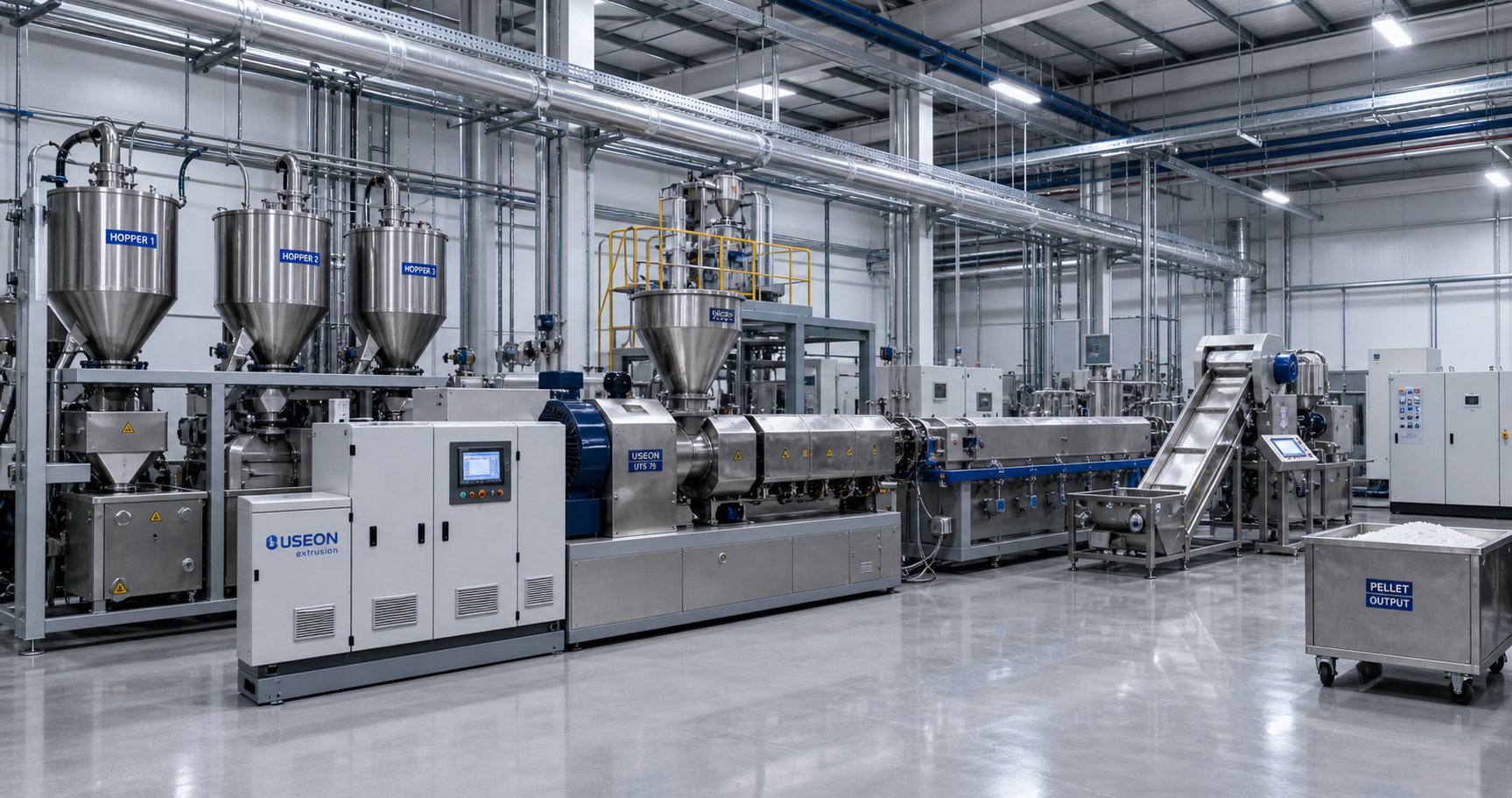
When to Choose a Co-Rotating Twin Screw Extruder
You've seen how the machine works, what each screw element does, how wear affects performance, and how to troubleshoot when things go sideways. But all of that knowledge serves one fundamental question: is a co-rotating twin screw plastic extruder actually the right technology for your specific operation - and if so, what should you prioritize when specifying or upgrading one?
This isn't a trivial decision. A well-matched machine becomes an engine of profitability for 15 to 20 years. A poorly matched one becomes a chronic source of quality problems, wasted energy, and frustrated operators. The difference often comes down to asking the right questions before the purchase order is signed - and planning for long-term component supply just as carefully as you plan the initial investment.
When a Co-Rotating Design Is the Right Choice
Not every plastics processing job needs the mixing intensity, modularity, and throughput that a co-rotating platform delivers. Some applications are better served by simpler, less capital-intensive equipment. The key is matching the machine's strengths to your actual processing demands - not buying capability you'll never use, and not underbuying and struggling with limitations for years.
A co-rotating twin screw extruder is the clear choice when your application involves any of the following:
- Compounding filled or reinforced plastics - glass fiber, mineral fillers, carbon fiber, or any formulation requiring dispersive mixing to break agglomerates and distributive mixing to spread them uniformly throughout a polymer matrix.
- Producing masterbatch concentrates - color, additive, or specialty concentrates where pigment dispersion to primary particle size and homogeneous distribution are non-negotiable quality requirements.
- Processing recycled polymers - post-consumer or post-industrial waste streams with inconsistent melt flow, mixed polymer types, moisture, and volatile contaminants that demand multi-stage devolatilization.
- Reactive extrusion - grafting, crosslinking, controlled degradation, or in-situ polymerization where precise residence time distribution, temperature control, and intensive mixing govern reaction outcomes.
- Any application demanding consistent output quality at high throughput - the self-wiping geometry, modular screw flexibility, and starve-fed operation mode give processors unmatched control over compound uniformity batch after batch.
Where does a co-rotating machine not make sense? Profile extrusion of rigid PVC - window frames, siding, pipe - is the classic counter-example. These applications need strong positive conveying and high pressure generation with relatively gentle shear, which is exactly what a conical twin screw extruder delivers. The conical design's tapered screws generate excellent pressure buildup in a compact footprint, and PVC's thermal sensitivity benefits from the lower shear environment. Similarly, simple pipe extrusion or film blowing with single-resin feedstocks that require minimal mixing are often handled more cost-effectively by single-screw extruders, which carry a lower twin screw extruder price tag and simpler operation.
The decision framework is straightforward: if your process demands intensive mixing, multiple feed points, vacuum devolatilization, or frequent formulation changes, co-rotating wins. If your process is primarily pressure-driven with low mixing requirements and a single polymer feedstock, simpler alternatives earn their place.
Key Specifications to Evaluate
Once you've confirmed that a co-rotating platform fits your application, the next step is narrowing down the right machine among the many options available from twin screw extruder manufacturers worldwide. Comparing machines on headline specs alone - maximum throughput, motor power - misses the parameters that actually determine whether the extruder will perform well on your specific formulations over the long haul.
Use this checklist when evaluating equipment from any supplier:
- Screw diameter - determines throughput capacity. Match it to your target production volume, keeping in mind that larger diameters mean higher capital cost, power consumption, and minimum batch sizes.
- L/D ratio - defines how much processing space is available. Standard compounding typically needs 40:1 to 44:1. Reactive extrusion, multi-stage devolatilization, or highly filled compounds may require 48:1 to 52:1 or longer. Don't over-specify - longer barrels increase cost and can extend residence time beyond what heat-sensitive materials tolerate.
- Torque density (Nm/cm cubed) - the gearbox's ability to deliver mechanical energy per unit of screw volume. High-torque machines (10-12 Nm/cm cubed and above) handle stiff polymers and heavily filled compounds without overloading. Standard machines (6-8 Nm/cm cubed) suit softer polymers but will struggle with engineering plastics.
- Maximum screw speed (RPM) - higher speed capability provides flexibility for throughput and mixing intensity adjustments, but remember that running at maximum speed increases shear and wear. Target machines that let you achieve your desired output at 60-80% of rated speed.
- Number of barrel zones - more zones mean finer temperature profile control. For complex formulations requiring distinct thermal zones for melting, mixing, and cooling before the die, additional zones provide the resolution operators need.
- Available vent ports - at least one vacuum vent is standard; demanding applications like recycled polymer processing or reactive extrusion may need two or three sequential vents to achieve target volatile reduction.
- Barrel and screw metallurgy options - verify that the supplier offers nitrided steel, bimetallic, PM-HIP, and coated options to match your formulation's abrasion and corrosion demands. A machine that only comes with standard nitrided elements will struggle in high-glass-fiber environments.
Beyond the extruder itself, consider the total line cost. A complete compounding line - extruder, feeders, side stuffers, screen changer, pelletizer, and controls - typically runs 2.5 to 3 times the extruder-only price. Budgeting for the extruder alone and then scrambling to fund downstream equipment is a mistake that delays startup and compromises line performance. Factor in installation, operator training, utility requirements (power, cooling water, compressed air), and a starter inventory of spare screw elements and screens.
Building a Reliable Supply Chain for Wear Components
Here's what separates operations that run smoothly for years from those that lurch from one crisis to the next: proactive wear component planning. The initial machine purchase is a one-time event. Replacing worn barrels and screw elements is a recurring operational reality - and how you manage that supply chain directly impacts uptime, compound quality, and production economics.
Imagine this scenario: your barrel bore measurements during a scheduled inspection show clearance has widened beyond tolerance in the kneading zone. Production is still running, but compound properties are drifting. You need a replacement barrel segment - and you need it within weeks, not months. If you haven't established a supplier relationship and lead times catch you off guard, you're either running degraded quality until the part arrives or shutting the line down entirely.
Proactive supply chain management means:
- Establishing supplier relationships early - before wear reaches critical levels. Engage with specialists who understand your barrel geometry, metallurgy requirements, and lead time constraints. Suppliers like NANHAIYA engineer parallel twin screw barrels for stable conveying, mixing, and high-wear plastics processing across compounding, masterbatch, recycling, and pelletizing operations - exactly the kind of focused expertise you want in a wear component partner.
- Evaluating metallurgy options for your specific formulations - don't default to the cheapest element material. If you're running 30% glass-fiber-filled PA66, nitrided steel elements will wear out in a fraction of the time PM-HIP elements last. Calculate cost-per-kilogram-of-compound-produced, not just cost-per-element, to find the true economic optimum.
- Planning replacement cycles proactively - track wear measurements over time, establish trend lines, and predict when components will reach end-of-life. Order replacements when measurements hit a trigger threshold - not when the line goes down. A common practice among well-managed operations is keeping one full set of critical spare screw elements and at least one replacement barrel segment in inventory at all times.
- Standardizing specifications - when working with multiple twin screw extruder manufacturers or sourcing replacement parts from third-party suppliers, maintain detailed dimensional and metallurgy specifications for every wear component on every machine in your facility. This eliminates guesswork during reordering and ensures replacement parts match original tolerances.
The financial logic is compelling. Unplanned downtime on a compounding line can cost $5,000 or more per day in lost production alone - before accounting for rush shipping fees on emergency parts, overtime labor for unscheduled maintenance, and potential penalties for missed customer delivery commitments. A modest investment in spare component inventory and supplier relationships eliminates most of that risk entirely.
Operational success with a co-rotating twin screw plastic extruder depends not only on the initial machine selection but on maintaining a dependable, proactive supply chain for the wear components that keep it running at peak performance year after year.
Choosing the right co-rotating extruder isn't just a purchasing decision - it's an engineering commitment that spans the entire lifecycle of the equipment. Get the specifications right, match them to your materials, invest in the right metallurgy from the start, and build the supply chain that keeps your line productive long after the commissioning engineers have left the building. That's what most engineers miss - and that's what separates compounding operations that merely run from those that truly perform.
Frequently Asked Questions About Co-Rotating Twin Screw Plastic Extruders
1. What is the difference between co-rotating and counter-rotating twin screw extruders?
Co-rotating twin screw extruders have both screws turning in the same direction, creating a self-wiping intermeshing zone that delivers high-intensity dispersive and distributive mixing with excellent throughput. Counter-rotating designs rotate screws in opposite directions, offering stronger pressure generation and gentler shear, which makes them better suited for applications like rigid PVC profile and pipe extrusion. Co-rotating machines dominate compounding, masterbatch production, reactive extrusion, and recycling because of their superior mixing flexibility and modular screw design.
2. What L/D ratio should I choose for a twin screw compounding extruder?
The ideal L/D ratio depends on your process complexity. Simple compounding with a single feed point and minimal venting works well at 32:1 to 36:1. General-purpose operations - color masterbatch, standard filled compounds with one or two vent ports - typically require 40:1 to 44:1. The most demanding tasks, including reactive extrusion, multi-stage devolatilization, and heavily filled formulations needing multiple feed points, call for 48:1 to 52:1. Longer barrels cost more and increase footprint, so avoid over-specifying beyond what your formulations actually need.
3. How do I know when twin screw barrel and screw elements need replacement?
Key indicators include increased motor load at the same throughput and RPM, declining compound quality such as undispersed pigment specks or lower mechanical properties, visible scoring or wear marks on element surfaces, inconsistent melt temperature despite stable barrel setpoints, and rising specific energy consumption per kilogram of output. Regular bore diameter and screw element measurements during scheduled shutdowns help track wear progression. Establishing a supply chain with barrel specialists like NANHAIYA before components reach end-of-life prevents costly unplanned downtime.
4. What causes vent flooding in a co-rotating twin screw extruder?
Vent flooding occurs when molten polymer pushes up through vacuum vent ports instead of being conveyed downstream. The four primary causes are excessive fill level from overfeeding, insufficient melt seal created by restrictive elements upstream of the vent, excessive die backpressure from a blocked screen changer or cold die, and over-aggressive vacuum pulling low-viscosity melt out of the port. Solutions include reducing feed rate, adjusting screw profile to ensure conveying capacity under the vent is at least twice the upstream feeding capacity, performing screen changes, and throttling vacuum pressure.
5. What plastics and materials are best suited for co-rotating twin screw extrusion?
Co-rotating twin screw extruders excel with engineering plastics like PA, PBT, PC, and POM - especially when compounded with glass fiber or mineral fillers requiring intense dispersive and distributive mixing. They are the standard for color and additive masterbatch production where pigment dispersion to primary particle size is critical. Recycled polymers benefit from multi-stage devolatilization to remove moisture, odors, and volatiles. Bioplastics like PLA and PHA require the low residence time and precise temperature control that the self-wiping, efficient conveying design provides.
Written by
Nanhaiya Technical Team
Zhoushan Nanhaiya Plastic Machinery Co., Ltd.
The Nanhaiya technical team supports screw and barrel manufacturing projects through application review, technical communication, custom manufacturing coordination, and production and quality control.
Discuss Your Application
Related Articles
More insights on screw barrel technology and plastics processing.

Extruder Machine Decoded: From Raw Pellet To Finished Product
Oct 6, 2026
Learn how an extruder machine works, compare single-screw vs. twin-screw types, and get expert guidance on specs, troubleshooting, and selection.
Read Article
PE Pipe Making Machine Decoded: From Raw Resin to Flawless Pipe
Oct 4, 2026
Learn how a PE pipe making machine works, from resin to finished pipe. Covers components, material grades, automation, troubleshooting, and buyer selection tips.
Read Article
PVC Profile Making Machine Decoded: From Raw Resin To Profit
Oct 3, 2026
Learn how a PVC profile making machine works — extrusion process steps, key technical parameters, die design, calibration methods, maintenance, and total cost of ownership.
Read ArticleLooking for something else?
Search by material, symptom or product and jump straight to the relevant page.
These are navigation suggestions based on keyword matching — not a quotation, not a delivery commitment, and not a substitute for engineering review. Final specification is confirmed by our engineers against your drawings and processed material.
Need help with screw barrel selection?
Share your machine model, processed material and application. Our team can help with pricing and technical support.