

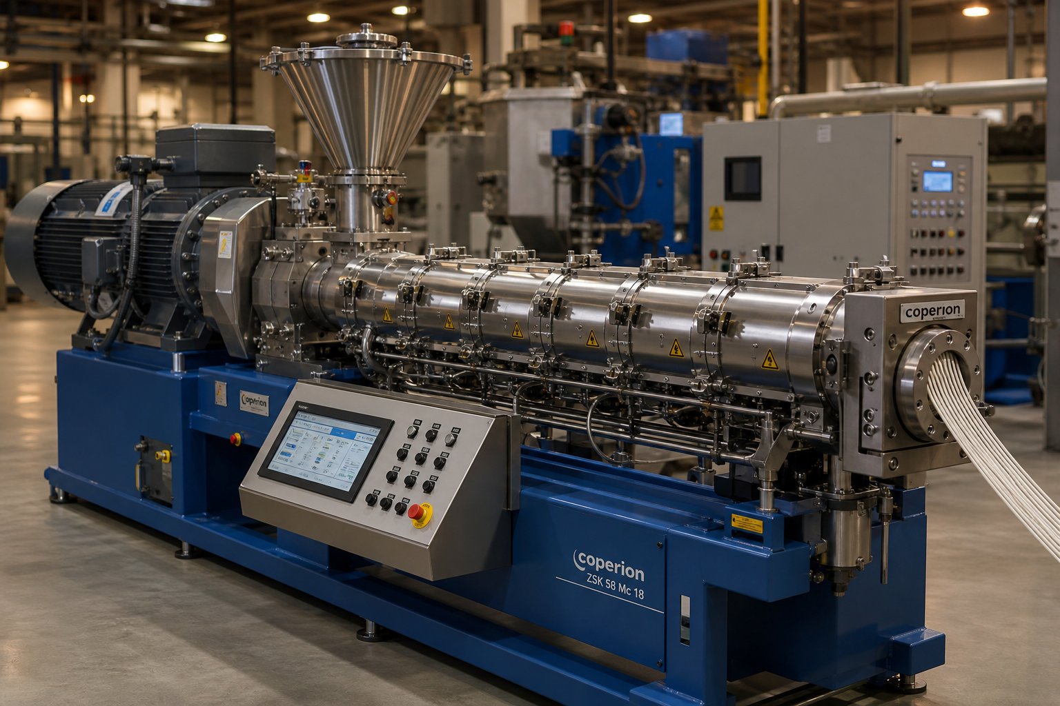
What Is a Corotating Twin Screw Extruder and Why It Matters
A corotating twin screw extruder is a continuous processing machine that uses two parallel, intermeshing screws rotating in the same direction inside a heated barrel to convey, melt, mix, and shape polymeric or other materials. Unlike a single screw extruder, which relies on flood-fed operation and a one-piece screw design, this twin-screw extruder operates in starve-fed mode, features modular screw and barrel assemblies, and delivers dramatically superior mixing performance. That combination of flexibility and control is exactly why the technology dominates virtually every sector of modern compounding.
Defining the Corotating Twin Screw Extruder
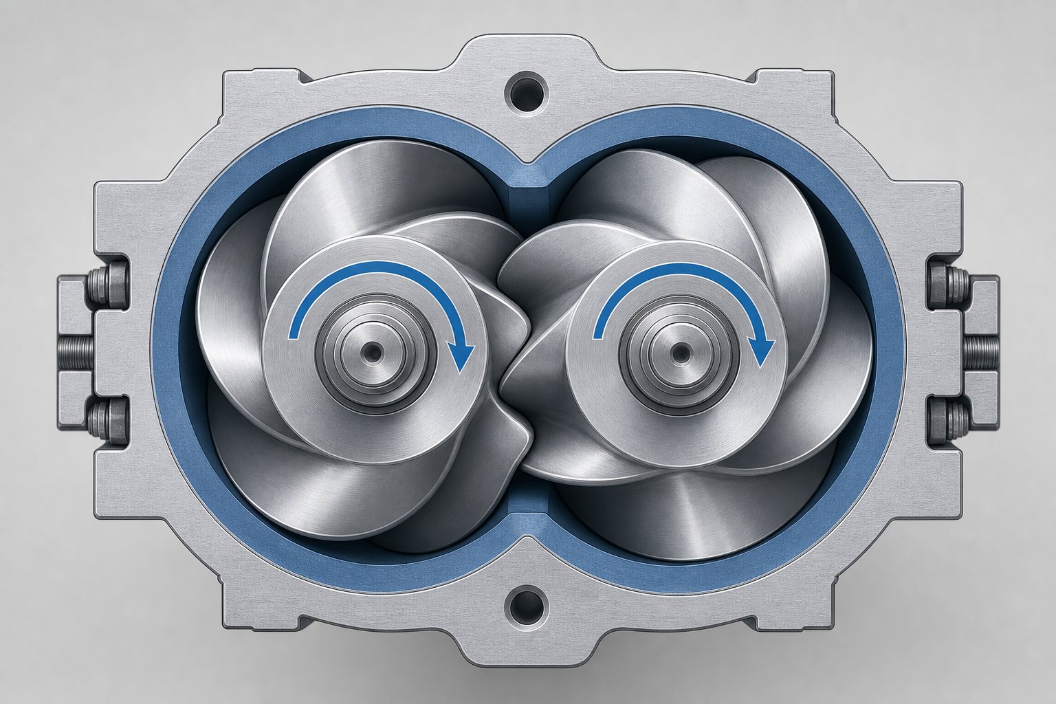
Imagine two helical screws placed side by side, their flights interlocking like loosely meshed gears. As both screws turn in the same direction, they create a figure-eight bore geometry inside the barrel. Material follows a controlled path, transferring from one screw to the other as it moves from the feed throat toward the die. This interscrew transfer is the fundamental mechanism that sets every co rotating twin screw extruder apart from simpler single-screw machines. Because the flight tip of one screw closely sweeps the root of the other, the design is described as "self-wiping" - material is continuously scraped off surfaces, preventing stagnation and ensuring a first-in, first-out flow sequence with a narrow residence time distribution.
Why This Technology Dominates Modern Compounding
Processors choose this type of twin screw extruder for several compelling reasons. The self-wiping action minimizes thermal degradation and speeds up material and color changeovers. Starve-fed operation decouples feed rate from screw speed, giving engineers independent control over throughput and mixing intensity. The modular design lets you rearrange screw elements and barrel sections to perform multiple unit operations - melting, dispersive and distributive mixing, reacting, devolatilizing - all within a single machine. A double screw extruder built on these principles handles everything from glass-fiber-filled engineering plastics to shear-sensitive pharmaceutical formulations.
The corotating intermeshing geometry combines self-wiping surfaces, independent speed and feed control, and modular configurability into a single platform - advantages no other extruder type delivers simultaneously.
This article serves as a comprehensive engineering-education resource that moves from first principles through advanced configuration strategy, filling a gap no single online source adequately addresses. The sections ahead explore intermeshing geometry, screw element design, processing zones, operating parameters, barrel construction, industrial applications, and scale-up - everything you need to understand why configuration changes everything.
Co-Rotating vs Counter-Rotating Twin Screw Extruders Compared
Two screws inside a barrel might sound like a simple concept, but the direction those screws turn fundamentally reshapes how material behaves during processing. The distinction between co rotating and counter rotating twin screw extruder designs is not just a mechanical detail - it determines mixing quality, throughput potential, pressure generation, and, ultimately, which applications each machine can handle. Understanding this difference is the first step toward selecting the right double screw extruder machine for a given process.
How Rotation Direction Changes Everything
In a corotating twin screw extruder, both screws spin in the same direction. As the flights intermesh, material is pulled through the nip region along the same path the screws are turning. Picture two conveyor belts running side by side in the same direction - material transfers back and forth between them, experiencing repeated folding, stretching, and reorienting. This action generates high shear in the intermeshing zone and produces excellent distributive mixing, spreading minor components like pigments, stabilizers, or nanofillers uniformly throughout a polymer matrix.
Counter-rotating screws, by contrast, turn in opposite directions. Material entering the intermeshing region gets squeezed between the approaching flight tips in a calendering-like action. Think of two rollers pressing dough flat: the material is compressed rather than folded. This generates substantial pressure but delivers lower mixing intensity. Because the screws push material together at the nip rather than transferring it across, counter-rotating designs are inherently better at building die pressure and worse at achieving the kind of intensive blending compounders demand.
A specialized variant worth knowing is the conical twin screw extruder. In this design, the screws taper from a large diameter at the feed end to a smaller diameter at the discharge. Conical screw extruder configurations are almost exclusively counter-rotating and are engineered for processing rigid PVC, where the combination of gentle shear and high pressure is critical. The tapered geometry provides a natural compression ratio without requiring complex screw element changes, making these machines simple and effective for a narrow but important range of applications.
Choosing Between Co-Rotating and Counter-Rotating Designs
Selecting the right machine depends on matching processing requirements to each design's strengths. The table below breaks down the key performance parameters across three configurations: parallel co-rotating, parallel counter-rotating, and conical counter-rotating.
| Parameter | Co-Rotating (Parallel) | Counter-Rotating (Parallel) | Counter-Rotating (Conical) |
|---|---|---|---|
| Mixing Capability | Excellent dispersive and distributive mixing | Moderate; limited distributive mixing | Low to moderate; gentle shear mixing |
| Maximum Screw Speed | High (up to 1,200+ RPM on modern machines) | Low to moderate (typically below 200 RPM) | Low (typically 5-50 RPM) |
| Throughput Range | Very wide; easily scaled from lab to production | Moderate; limited by speed constraints | Moderate; application-specific |
| Typical Applications | Compounding, masterbatch, reactive extrusion, devolatilization | PVC pipe, profiles, sheet extrusion | Rigid PVC pipe and profile extrusion |
| Pressure Generation | Moderate; relies on screw tip and die design | High; calendering action builds pressure efficiently | High; tapered geometry creates natural compression |
| Self-Wiping Behavior | Fully self-wiping | Partially self-wiping at best | Not self-wiping |
| Screw Wear Profile | Even wear; replaceable modular elements | Concentrated wear at intermesh; one-piece screws common | Concentrated wear at small-diameter end; one-piece screws |
You'll notice that co-rotating machines dominate the flexibility columns. Their modular screw and barrel design, combined with self-wiping geometry and high-speed capability, makes them the default choice for any process demanding intensive blending or frequent recipe changes.
When Counter-Rotating Makes More Sense
Editorial honesty matters here: counter-rotating designs are not inferior - they are purpose-built for different jobs. Rigid PVC processing, for instance, requires very high die pressures delivered at low shear to avoid thermally degrading a heat-sensitive polymer. A conical twin screw extruder accomplishes this naturally through its tapered geometry and slow screw speed, producing pipes and window profiles with excellent surface quality. Certain sheet and film applications also benefit from the calendering action of parallel counter-rotating machines, where uniform pressure across a wide die is more important than mixing intensity.
However, for compounding, masterbatch production, reactive extrusion, polymer recycling, and devolatilization, the co-rotating configuration remains the clear standard. Its ability to independently control mixing energy, accommodate modular screw profiles, and handle rapid product changeovers without material degradation is unmatched by any counter-rotating alternative.
The real question, then, is not just which direction the screws rotate - it is how you arrange the individual elements along those screws to achieve a specific processing result. That screw configuration strategy is where the corotating twin screw extruder truly distinguishes itself from every other design.
Intermeshing Geometry and the Self-Wiping Mechanism Explained
Screw rotation direction sets the stage, but geometry is what delivers the performance. Every advantage a corotating twin screw extruder holds over competing designs - superior mixing, minimal degradation, fast changeovers - traces back to two interrelated geometric features: the figure-eight bore profile and the self-wiping clearance between intermeshing screws. These are the details most technical resources gloss over, yet they dictate free volume, torque capacity, and material handling behavior at the most fundamental level.
The Figure-Eight Bore and Screw Geometry
Slice through any twin screw extruder barrel at a right angle to the screw axis, and you'll see two overlapping cylindrical bores forming a figure-eight cross section. Each bore houses one screw, and the overlap region - the intermesh zone - is where the flights of one screw penetrate into the channel of the other. The centerline distance between the two bores is always less than the sum of the screw radii; otherwise, the screws would never engage.
Three geometric dimensions govern everything that happens inside that bore: the screw outer diameter (OD), the screw inner diameter (ID, also called the root diameter), and the centerline distance between shafts. The flight depth - the space available for material to occupy - is simply the difference between OD and ID divided by two. Increase the flight depth, and you gain more free volume per screw revolution. However, a deeper channel means a smaller root diameter, which reduces the shaft cross-section available to transmit torque.
This trade-off is captured by the OD/ID ratio, arguably the single most important design parameter for twin screw extruders. A machine with a 1.4/1 OD/ID ratio has relatively shallow channels and a thick, strong shaft - good for torque, limited in volume. Push that ratio to 1.66/1 or higher, and the channels deepen substantially, offering significantly more free volume to process material. The engineering challenge is clear: how do you get both high volume and high torque?
The answer lies in shaft technology evolution. As documented in the historical development of TSE hardware, shaft designs have progressed from simple keyway shafts (standard in the 1950s, paired with 1.25/1 OD/ID ratios) through hexagonal shafts (1960s, 1.4/1), splined shafts (1990s, 1.55/1), and modern asymmetrical splined shafts (introduced around 2005, enabling OD/ID ratios of 1.66/1 and above). Each generation allowed a smaller-diameter shaft to carry more torque, freeing up cross-sectional area for deeper screw channels.
This progression matters enormously in practice because of a metric called torque density, measured in Nm/cm3. Torque density relates the gearbox's continuous torque output to the screw cross-sectional area it drives. Modern high-performance twin-screw extruders achieve torque densities around 18 Nm/cm3 - roughly 30% higher than previous-generation machines. In plain terms, higher torque density means you can process high-viscosity materials, heavily filled compounds, or engineering polymers at moderate screw speeds without tripping the drive's overload protection. It is the reason a modern extruder twin screw platform can compound 60% glass-fiber-filled polyamide at rates that would have stalled a machine built two decades ago.
Most corotating intermeshing twin screw extruders are bilobal - each screw cross section has two flight tips (lobes) wiping the barrel wall. This is a geometric constraint: at typical OD/ID ratios between 1.4/1 and 1.8/1, only two lobes can fit without the screws interfering with each other during rotation. For specialized laboratory applications requiring very low free volume and maximum torque, a 1.2/1 OD/ID ratio can accommodate trilobal elements, but these remain niche configurations used primarily for processing small test batches of 20 grams or less.
Self-Wiping Action and Why It Prevents Degradation
Here is where geometry becomes processing magic. In a corotating design, both screws spin in the same direction, which means surface velocities at the intermesh point move in opposite directions. The flight tip of one screw continuously traces along the root of its neighbor, scraping material off the metal surface with every revolution. Simultaneously, the barrel wall is wiped by each screw's outermost flight. The result? No point on either screw or barrel surface retains stagnant material for more than a single rotation cycle.
Why does this matter so much? Consider what happens without self-wiping. In any screw extrusion process, molten polymer can adhere to hot metal surfaces and sit there for minutes - sometimes hours - while fresh material flows past. That stagnant layer absorbs heat continuously, degrades, crosslinks, and eventually breaks free as black specks, gels, or carbonized particles contaminating the product stream. For medical-grade, food-contact, or color-critical applications, even a single degraded speck means rejected product.
Self-wiping eliminates those dead zones entirely. Every surface is renewed with each screw revolution, producing two outcomes that matter for daily operations:
- Reduced thermal degradation: Material experiences a narrow, predictable residence time distribution rather than an unpredictable mix of fresh and overcooked polymer. The more filled the screws, the tighter this distribution becomes; the more starved, the wider - but in either case, the self-wiping action prevents any fraction of material from lingering indefinitely.
- Faster changeovers: Without stagnant layers clinging to screw roots and barrel walls, purging between colors or materials requires less time and less purge compound. In production environments running multiple formulations per shift, this translates directly into higher machine utilization and lower scrap rates.
The self-wiping mechanism also sequences the material into a true first-in, first-out flow pattern. Combined with the figure-eight transfer path, this means every particle of polymer passes through the same series of shear zones in roughly the same order and for roughly the same duration. That uniformity of thermal and mechanical history is what makes twin-screw extruders so reliable for compounding sensitive formulations - from heat-labile pharmaceutical dispersions to shear-sensitive color concentrates.
Self-wiping is the single most important geometric feature distinguishing corotating intermeshing designs from every other extruder type - it eliminates stagnant material, ensures uniform residence time, and enables the fast changeovers that modern production demands.
Geometry, of course, only defines the playing field. The real processing work - melting, dispersing, distributing, devolatilizing - falls to the individual screw elements arranged along those self-wiping shafts. How those elements are selected and sequenced is where a twin extruder transforms from a standardized platform into a purpose-built processing tool.
Screw Element Design and Configuration Strategy
Every corotating twin screw extruder ships with the same basic platform - a gearbox, a motor, modular barrels, and self-wiping shafts. What turns that platform into a high-performance compounding extruder, a reactive processor, or a devolatilization workhorse is the sequence of individual screw elements arranged along those shafts. Choosing the right elements - and placing them in the right order - is the single most powerful tool engineers have for controlling product quality in twin screw extrusion.
Types of Screw Elements and Their Functions
Screw elements on a corotating machine fall into four broad families, each engineered for a specific job. Conveying elements move material forward. Kneading blocks melt and mix. Specialized mixing elements redistribute or disperse. Reverse elements create back pressure. The table below breaks down each type with its function, shear characteristics, conveying behavior, and typical location within the screw profile.
| Element Type | Primary Function | Shear Level | Conveying Capacity | Typical Placement |
|---|---|---|---|---|
| Conveying Element (Forward Pitch) | Transports material downstream; builds mild pressure | Low | High (proportional to pitch) | Feed zone, between processing sections, discharge zone |
| Kneading Block - Narrow Disc (e.g., 30° stagger) | Gentle melting and distributive mixing | Low to moderate | Moderate forward conveying | Early melting zone; shear-sensitive formulations |
| Kneading Block - Wide Disc (e.g., 45° stagger) | Intensive melting and dispersive mixing | High | Moderate forward conveying | Primary melting zone; pigment dispersion sections |
| Kneading Block - Neutral (90° stagger) | Maximum dispersive and distributive mixing; no net conveying | Very high | None (neutral) | Mixing zones requiring high shear and long residence |
| Kneading Block - Reverse Stagger | Creates back pressure; increases fill and residence time upstream | Very high | Negative (pushes material backward) | End of mixing zones; before vent sections to seal vacuum |
| Toothed Mixing Element (ZME / TME) | Excellent distributive and dispersive mixing with controlled shear | Moderate to high | Low (depends on lead) | Mixing zones for fillers and additives |
| Turbine Mixing Element | High distributive mixing at low shear stress | Low to moderate | Low | Post-mixing homogenization; shear-sensitive blends |
| Reverse Conveying Element | Creates strong back pressure; seals vent zones | Moderate | Negative | Upstream of vent ports; melt seal sections |
A few things stand out. Conveying elements are your workhorses - they fill most of the screw length and dictate material transport speed. Kneading blocks, in their various configurations, handle the heavy lifting of melting and mixing. Research from Paderborn University using 3D CFD flow simulations with particle tracking confirmed that toothed mixing elements (ZME) outperform kneading blocks for both distributive and dispersive mixing, generating more uniform particle distributions and higher shear stresses across a wider population of tracked particles. Yet kneading blocks remain indispensable for initial melting, where their disc geometry forces polymer pellets through narrow gaps between flight tips and barrel walls.
Building a Screw Profile for Specific Processing Goals
Designing a screw profile is essentially sequencing these elements to create a story the material must live through - from solid pellet to finished melt strand. Engineers talk about "restrictive" versus "open" configurations. An open profile uses mostly conveying elements with only brief kneading sections, giving material a short residence time and low shear history. A restrictive profile stacks multiple kneading blocks and reverse elements, forcing higher fill levels, longer residence, and more intensive mixing. The right balance depends entirely on what the product demands.
Here are three common configuration strategies that illustrate the logic:
- General polymer compounding profile: Forward conveying elements in the feed zone → a block of 45° and 90° kneading discs for melting and initial mixing → toothed or turbine mixing elements for distributive blending → forward conveying elements to transport melt past an atmospheric or vacuum vent → a final conveying section with tightening pitch to build die pressure. This is the default starting point for most compounding twin screw extruder setups processing filled or blended thermoplastics.
- Filler masterbatch profile (e.g., 70% CaCO3 in polyethylene): The challenge here is distributing enormous filler volumes uniformly without over-shearing the polymer or breaking filler particles to sizes that increase viscosity uncontrollably. Engineers typically use a moderate melting zone with 45° kneading blocks, followed by a side-stuffer feed port for the filler, then multiple stages of toothed mixing elements rather than aggressive kneading blocks. The ZME's ability to generate high distributive mixing without the extreme shear peaks of 90° kneading blocks makes it ideal - particles get spread uniformly without being ground into problematic fines.
- Reactive extrusion profile (e.g., maleic anhydride grafting): Residence time precision is critical because the chemical reaction must proceed long enough for conversion but not so long that side reactions or degradation occur. A twin screw compounding extruder configured for reactive extrusion typically features a short, aggressive melting section (wide kneading blocks at 60° or 90°), followed by a long series of moderately restrictive elements - often alternating narrow kneading blocks and conveying segments - that maintain a controlled fill level and predictable residence time through the reaction zone. Reverse elements may be placed strategically to create melt seals separating the reaction zone from a downstream vacuum vent, where byproducts are removed.
The key insight? No single element type handles every job. It is the arrangement - the configuration - that turns a general-purpose machine into a specialized processing tool. Two compounding extruders with identical motors, gearboxes, and barrels can produce wildly different product quality simply because one engineer sequenced the screw elements more intelligently than the other.
How Kneading Block Stagger Angle Affects Mixing
Kneading blocks are assembled from individual disc-shaped elements stacked along the shaft with a fixed angular offset between each disc. That offset - the stagger angle - is the most impactful variable an engineer can adjust within the mixing zone. Imagine fanning a deck of cards: the wider you spread them, the more each card redirects airflow. Kneading disc stagger works the same way with polymer melt.
- 30° stagger: Strong forward conveying with gentle mixing. Material moves through quickly, experiencing modest shear. Use this where you need some mixing action without building significant back pressure - for instance, finishing the melt of an already-softened polymer.
- 45° stagger: A balanced compromise. Forward conveying drops compared to 30°, but shear stress rises meaningfully. This is the workhorse angle for most plasticizing and initial mixing tasks in twin screw extrusion.
- 60° stagger: Forward conveying decreases further, and residence time in the kneading zone increases. Mixing intensity rises. Good for applications needing stronger dispersive action, like breaking down pigment agglomerates or delaminating layered mineral fillers.
- 90° stagger (neutral): Zero net forward conveying. Each disc is perpendicular to the next, creating maximum shear and the longest local residence time. The Paderborn University study confirmed that 90° kneading blocks achieve better distributive mixing indices than 45° blocks under identical speed and material conditions - the KB24 (90° stagger, 24 mm length) consistently outperformed the KB45 (45° stagger, 24 mm length) across all tested rotational speeds.
Reverse-stagger kneading blocks flip the offset direction, actively pushing material backward. This creates a localized pressure dam that forces the upstream section to fill completely, dramatically increasing both shear exposure and residence time. Engineers place reverse kneading blocks at the end of a mixing zone to ensure the preceding elements operate fully filled - a critical requirement when you need every gram of material to pass through the high-shear region rather than slipping through partially starved channels. Reverse elements also serve as melt seals ahead of vacuum vent ports, preventing air from being sucked upstream through the melt.
One more detail worth noting: kneading disc width matters alongside stagger angle. Narrower discs with gaps between them promote distributive mixing by creating more reorientation events per unit length. Wider discs maximize the shear surface area, favoring dispersive mixing. Combining disc width and stagger angle gives engineers a finely tunable toolkit - a 90° block with narrow discs and gaps delivers a very different mixing profile than a 90° block with wide, tightly packed discs, even though the stagger angle is identical.
Screw configuration is the primary tool for process optimization in corotating twin screw extrusion - no change in temperature, speed, or feed rate can compensate for a fundamentally mismatched element sequence.
With the right elements locked in place, the screw profile defines a series of distinct processing zones stretching from the feed throat to the die face. Each zone carries out a specific task - solids conveying, melting, mixing, devolatilizing, or pressure buildup - and the interaction between zones determines whether the final product meets specification or falls short.
Processing Zones Inside a Twin Screw Extruder Plastic Compounding Line
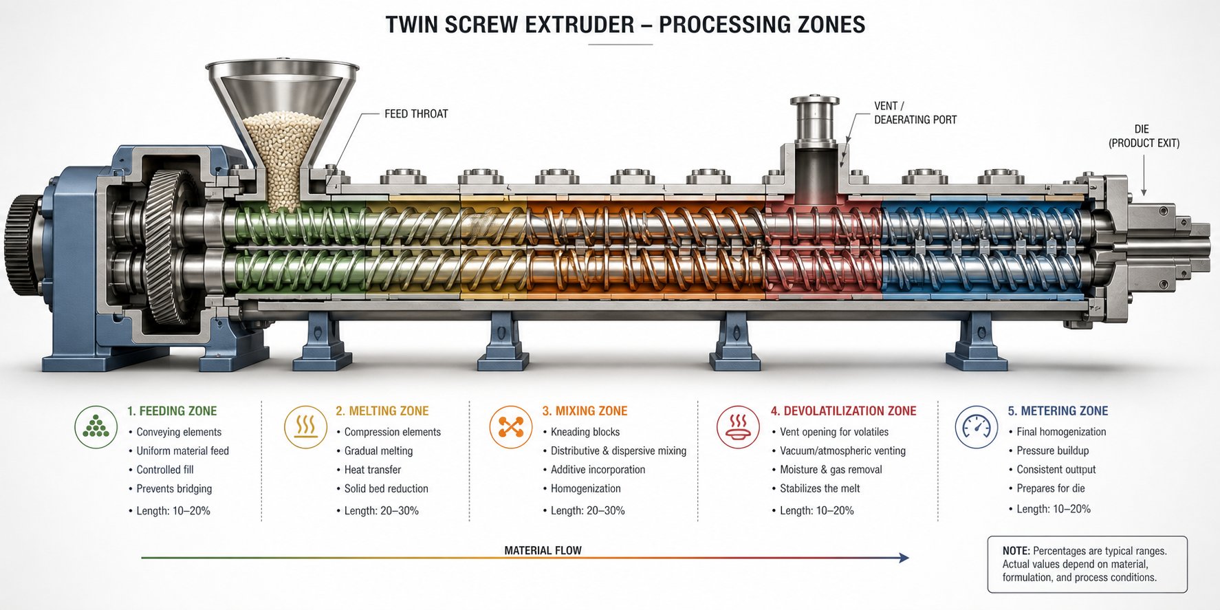
Screw elements define what each zone can do. The processing zones themselves define what actually happens to the material as it travels from a pile of cold pellets at the feed throat to a uniform, pressurized melt stream exiting the die. Think of these zones as chapters in the material's journey - each one builds on the last, and skipping or mismanaging any single chapter compromises the entire story. Most explanations of a plastic twin screw extruder treat these zones as a simple list. The reality is more nuanced: every zone interacts with its neighbors, and the balance between screw speed, feed rate, and fill level governs how each zone performs.
Solids Conveying and Melting Zones
Here is a fundamental operating concept that many resources overlook entirely: a corotating twin screw extruder does not flood-feed. Unlike a single screw machine where you fill the hopper and gravity does the rest, this twin-screw extruder plastic processing system uses a gravimetric or volumetric feeder mounted above the feed barrel to meter material at a controlled rate. The feeder - not the screw speed - sets the throughput. The screws simply accept whatever the feeder delivers.
Why does this matter? Because it decouples two variables that are permanently locked together on a single screw extruder: output and mixing intensity. On a flood-fed machine, speeding up the screw increases both throughput and shear simultaneously - you cannot change one without changing the other. On a starve-fed twin screw plastic extruder, you can hold feed rate constant and increase screw speed to intensify mixing, or hold screw speed constant and increase feed rate to boost output with less mixing energy per kilogram. This independence is the reason engineers can fine-tune product quality with a precision that single-screw platforms simply cannot match.
When polymer pellets drop into the feed barrel, they land on partially filled conveying elements - the screws are "starved," not completely packed with material. Large-pitch forward-conveying elements with deep screw grooves dominate this section, maximizing free volume to prevent bridging and ensuring smooth material intake. Drag flow generated by screw rotation pushes the pellets forward, and the loose fill means minimal pressure develops at this stage.
As material advances into the melting zone, two energy sources work together to convert solid pellets into a continuous melt. First, the barrel's electrically heated zones conduct thermal energy inward through the metal walls. Second - and more significantly at high screw speeds - viscous dissipation from kneading elements converts mechanical energy into heat directly within the polymer mass. Kneading blocks compress, shear, and fold the softening pellets between their disc faces and the barrel wall, generating frictional heat exactly where it is needed most. The balance between barrel conduction and viscous dissipation shifts depending on operating conditions: at low speeds, barrel heat dominates; at high speeds, mechanical energy input can account for the majority of the melting work.
The relationship between screw speed, feed rate, and fill level is worth pausing on. Increase the feed rate while holding screw speed constant, and the screws fill more completely - residence time rises, and material spends longer in each processing zone. Increase screw speed at a constant feed rate, and the opposite happens: fill level drops, residence time shortens, and the specific energy input (energy per kilogram of material) rises because the screw is doing more mechanical work on less material per revolution. Understanding this three-variable interaction is the key to controlling melt temperature, mixing quality, and throughput on any twin screw extruder plastic compounding line.
Mixing Zones for Dispersive and Distributive Blending
Once the polymer is fully molten, the real work of compounding begins. Mixing in a corotating twin screw extruder falls into two distinct categories, and confusing them is a common source of processing problems.
Dispersive mixing breaks things apart. Imagine a clump of carbon black agglomerate embedded in a polyethylene melt. That agglomerate needs to be shattered into individual particles small enough to deliver the desired color intensity and UV protection. Dispersive mixing accomplishes this by subjecting the agglomerate to stress levels that exceed the cohesive forces holding it together. Kneading blocks with wide discs and high stagger angles (60° or 90°) are the primary tools here - they force melt through narrow gaps between disc tips and the barrel wall, generating the intense shear stress required to fragment agglomerates, break down oversized filler particles, and reduce the droplet size in polymer blends.
In the co extrusion process and multilayer applications, dispersive mixing upstream of the die ensures that each polymer layer has uniform properties before layers are combined - an inconsistently mixed base stream shows up as visual defects or delamination in the final co-extruded product.
Distributive mixing spreads things evenly. After agglomerates have been broken down, the resulting fine particles or droplets need to be distributed uniformly throughout the entire polymer matrix. Distributive mixing does not require high stress - it requires many reorientation events. Toothed mixing elements and turbine-style elements excel at this task because they split, recombine, and redirect melt flow repeatedly without imposing the extreme shear peaks that could degrade shear-sensitive additives or excessively heat the polymer.
Most real-world formulations need both types. A color masterbatch, for example, requires dispersive mixing to break pigment agglomerates down to primary particle size, followed by distributive mixing to spread those particles uniformly so the final product shows no streaks or color variation. An engineer configures the screw to deliver dispersive action first (aggressive kneading blocks), then transitions into distributive elements (toothed or turbine mixers) downstream - sequencing that mirrors the logic covered in the screw element strategy discussion.
Devolatilization and Pressure Buildup Zones
Not everything that enters the extruder belongs in the final product. Moisture absorbed during storage, residual solvents from reactive processes, trapped air, and volatile reaction byproducts all need to escape before the melt reaches the die. That is the job of the devolatilization zone.
Devolatilization works by reducing pressure over the melt surface and maximizing the area available for volatile escape. Large-pitch conveying elements positioned beneath the vent port expand the melt's free surface and reduce the degree of channel fill, allowing volatiles to flash out of the melt and exit through vent openings in the barrel. For atmospheric venting, the barrel section simply has an open port. For deeper volatile removal, a vacuum pump draws negative pressure through the vent - typically ranging from 50 to 200 mbar absolute - pulling trapped gases and vapors out of the melt far more aggressively than atmospheric exposure alone.
A critical design detail sits just upstream of each vent port: a melt seal. Reverse kneading blocks or reverse conveying elements create a fully filled, pressurized plug of polymer that prevents the vacuum from pulling air backward through the screw channel. Without this seal, atmospheric air would get sucked into the machine through the feed end, defeating the entire purpose of the vacuum system - and potentially oxidizing the hot polymer in the process. Getting the melt seal right is one of the more challenging aspects of screw design, because too much restriction causes excessive pressure drop and local overheating, while too little restriction lets the seal break and vent flooding occurs.
After devolatilization, the final zone has a straightforward mission: build enough pressure to push melt through the die at a stable, consistent rate. The metering zone uses forward-conveying elements with small or standard pitch and shallow screw grooves to compress the melt, increase fill to 100%, and develop the back pressure needed to feed a strand die, sheet die, or pelletizing system evenly. The barrel temperature in this zone is typically held close to the desired final melt temperature, with minimal additional shear input - the goal is stability, not further mixing.
Seeing all these zones laid out sequentially helps clarify how a corotating twin screw extruder transforms raw ingredients into finished product:
- Feeding zone: Accepts metered raw material from the gravimetric feeder into partially filled, large-pitch conveying elements.
- Solids conveying zone: Transports pellets or powder forward by drag flow, gradually compacting the material bed.
- Melting/plasticizing zone: Converts solid material into a homogeneous melt through barrel heat conduction and viscous dissipation from kneading elements.
- Mixing zone (dispersive): Applies high shear stress to break agglomerates, reduce droplet sizes, and fragment oversized filler particles.
- Mixing zone (distributive): Spreads dispersed components uniformly throughout the polymer matrix using frequent flow-splitting and reorientation.
- Devolatilization zone: Removes moisture, solvents, and volatile byproducts through atmospheric or vacuum venting over a renewed melt surface.
- Metering/pressure buildup zone: Builds stable melt pressure for consistent delivery through the die.
Each zone's performance depends not only on its own screw elements and barrel temperature but also on what happens upstream and downstream. A poorly designed melting zone delivers unmelted particles into the mixing section, where they act as defects rather than feedstock. A weak melt seal lets vacuum break through, turning the devolatilization zone into a source of contamination rather than purification. This interdependence is exactly why experienced process engineers evaluate the entire screw profile as a system rather than optimizing individual zones in isolation.
Knowing what each zone is supposed to accomplish is essential - but translating that knowledge into repeatable product quality requires precise control over the operating parameters that govern every zone's behavior. Screw speed, feed rate, and barrel temperature profiles are the levers that bring a well-designed screw configuration to life - or expose its weaknesses.
Operating Parameters and Process Control Essentials for Twin-Screw Extruder Machines
A perfectly configured screw profile is only half the equation. Without precise control over the operating parameters that drive it, even the best element sequence underdelivers. Screw speed, feed rate, and barrel temperature are the three primary levers operators use to translate mechanical design into consistent product quality - and misunderstanding how they interact is the fastest route to off-spec material, wasted energy, and unnecessary downtime. Whether you are commissioning a brand-new twin-screw extruder machine or optimizing a used twin screw extruder inherited from a previous production line, the principles covered here apply universally.
Screw Speed, Feed Rate, and Their Interaction
Corotating twin screw extruders operate in starve-fed mode. This single fact changes the entire control philosophy compared to flood-fed single-screw machines. The gravimetric feeder dictates throughput - period. Screw speed, meanwhile, controls mixing intensity, residence time, and specific energy input. These two variables are independent, and understanding their interaction is the foundation of process control.
Imagine holding the feed rate constant at 200 kg/h and increasing screw speed from 300 RPM to 600 RPM. What happens? The screws turn faster, but the same amount of material enters per minute. Each revolution now carries less material, so the degree of fill inside the screw channels drops. Lower fill means shorter residence time - material spends fewer seconds traveling from feed throat to die. Simultaneously, the motor is working harder per kilogram of polymer processed, so the specific mechanical energy (SME, measured in kWh/kg) increases. Higher SME translates to more viscous dissipation and, consequently, a higher melt temperature.
Flip the scenario: hold screw speed constant and increase feed rate. Fill level rises, residence time increases, and SME decreases because the same mechanical work is spread across more material. Research on twin-screw compounding parameters confirms that throughput has a considerably larger impact on residence time than screw speed does - a finding that surprises many operators who instinctively reach for the speed dial when they want to adjust process behavior.
The practical takeaway? Use screw speed primarily to control mixing intensity and melt temperature. Use feed rate primarily to control throughput and residence time. Adjusting both simultaneously without understanding which variable is driving the change is a recipe for chasing problems in circles.
Barrel Temperature Profile and Melt Temperature Management
The barrel of a corotating twin screw extruder is divided into individually controlled heating and cooling zones - typically anywhere from 8 to 12 zones on a production-scale machine. Each zone has its own set temperature, managed by cartridge or band heaters for heating and water channels or forced air for cooling. Engineers establish a temperature profile that progresses from the feed end to the die, and this profile interacts with viscous dissipation from the screw elements to determine the actual melt temperature the polymer experiences.
Here is a critical distinction many operators miss: barrel set temperature and actual melt temperature are not the same thing. The barrel set temperature is what you program into the controller. The melt temperature is what the polymer actually reaches - and it is almost always higher than the set point in the mixing zones, because kneading blocks and restrictive elements generate substantial frictional heat inside the polymer itself. On a heavily filled compound running at high screw speed, melt temperature can exceed the barrel set point by 20 to 40 degrees Celsius or more.
This gap matters because melt temperature - not barrel temperature - is the critical quality parameter. It determines whether the polymer degrades, whether additives activate properly, whether crystallization kinetics in the pelletizing bath produce the desired morphology, and whether the compounder's molding or extrusion customers can produce high-quality parts from the pellets. Experimental data from Leistritz demonstrated that an aggressive melting-zone screw design produced melt temperatures 10 to 30 degrees Celsius higher than an extended melting-zone design at the same screw speeds - with the aggressive configuration also causing visible degradation (smoke and discoloration) at elevated RPM. The extended design not only ran cooler but also achieved higher attainable throughput rates before reaching the 85% torque limit.
Perhaps counter-intuitively, raising the barrel set temperature in the early zones can actually reduce melt temperature. Higher barrel heat softens the polymer earlier, so the kneading blocks encounter less resistance when they begin shearing. Less resistance means less viscous dissipation, which lowers the mechanical contribution to melt temperature. This "reverse temperature profile" strategy - higher set points near the feed, lower set points near the die - is a well-established technique pioneered on machines like the Werner & Pfleiderer twin screw extruder platform and widely adopted across the industry.
One more factor often overlooked: pressure at the discharge end contributes directly to melt temperature. A useful rule of thumb from compounding research by Leistritz engineers estimates the temperature rise as approximately half the die pressure in bar. So if your die generates 40 bar of back pressure, expect roughly a 20-degree Celsius temperature bump at the discharge. Front-end design - die geometry, screen pack mesh size, melt pump configuration - must be considered alongside screw design and barrel profile when managing melt temperature holistically.
Troubleshooting Common Processing Problems
Even experienced operators encounter issues. The difference between a quick recovery and hours of lost production often comes down to systematic diagnosis rather than guesswork. The table below covers the five most common processing problems on corotating twin screw extruders, their likely root causes, and the corrective actions that resolve them.
| Problem | Likely Causes | Corrective Actions |
|---|---|---|
| Surging (fluctuating die pressure and output) | Inconsistent feeder delivery; partially blocked feed port; insufficient melt seal before the die; screw elements worn beyond tolerance | Calibrate or replace gravimetric feeder; clean feed throat and check for bridging; add restrictive elements in the metering zone to stabilize pressure; inspect and replace worn screw elements |
| Poor dispersion (visible agglomerates, specks, or streaks in product) | Insufficient shear in mixing zone; incorrect kneading block stagger angle; feed rate too high relative to screw speed (low SME); filler added before polymer is fully melted | Replace mixing elements with higher-shear kneading blocks (wider discs, higher stagger angle); increase screw speed at constant feed rate to raise SME; relocate side-stuffer port downstream of the melting zone |
| Thermal degradation (discoloration, odor, reduced mechanical properties) | Excessive melt temperature from aggressive screw design; barrel set temperatures too low (forcing mechanical energy to dominate melting); excessive die pressure; residence time too long | Switch to an extended melting-zone screw design with narrow-disc kneading blocks; raise barrel temperatures in the feed and melting zones to reduce viscous dissipation; reduce die restriction; increase feed rate to shorten residence time |
| Vent flooding (melt rising into vent port and blocking vacuum line) | Melt seal upstream of vent too weak; fill level in vent zone too high; melt viscosity too low at vent location; vacuum level set too aggressively | Add or lengthen reverse kneading block or reverse conveying element upstream of the vent; reduce feed rate or increase screw speed to lower fill in the vent zone; reduce barrel temperature near the vent to increase local melt viscosity; reduce vacuum level gradually |
| Feed inconsistencies (erratic torque, uneven pellet quality) | Material bridging in hopper; feeder screw slipping on low-bulk-density powders; moisture in hygroscopic polymers causing clumping; inconsistent raw material particle size | Install hopper agitator or vibration device; switch to a feeder screw geometry designed for the specific material's bulk characteristics; pre-dry materials to recommended moisture content; screen or pre-blend raw materials for consistent particle size distribution |
Notice a pattern in the corrective actions: most solutions involve adjusting the interplay between screw configuration and operating parameters rather than changing a single variable in isolation. Surging, for example, might look like a feeder problem but could just as easily stem from worn screw elements that can no longer maintain a stable melt seal. Poor dispersion might seem like a speed issue, but relocating a side-stuffer port so filler enters fully molten polymer often delivers a bigger improvement than any RPM change. Systematic troubleshooting means considering the entire system - feeder, screw profile, barrel temperatures, and die design - as interconnected variables rather than independent knobs.
Mastering these operating parameters gives you control over what happens inside the barrel minute by minute. But the barrel itself - its modular construction, metallurgy, and thermal management hardware - defines the physical boundaries within which all of that control operates. How a barrel is designed, what it is made from, and how quickly it can heat and cool each zone directly shapes the range of processes any single machine can handle.
Barrel Design and Modular Construction for Process Flexibility
Screw elements get all the attention in most technical discussions, and for good reason - they are the primary mixing tools. But every screw element operates inside a barrel, and the barrel's design quietly determines what is possible. Where can you add a side feeder? How many vent ports fit in the process section? Can you switch from a 40:1 L/D compounding setup to a shorter 32:1 reactive extrusion layout without buying a new machine? The answers all live in the barrel. A corotating twin screw extruder's barrel is not a passive steel tube - it is a modular, reconfigurable platform that shapes the process just as fundamentally as the screw profile it houses.
Modular Barrel Sections and Zone Configuration
Unlike the one-piece barrels common on single-screw machines, twin screw and barrel assemblies on corotating extruders are built from individual modular sections bolted together end-to-end. Each section is typically 4 to 5 L/D in length, and the overall process length is described by the total L/D ratio - a 20-mm screw extruder with an 800-mm process section, for instance, runs at 40:1 L/D. Adding or removing barrel sections physically changes the machine's processing length, giving engineers a degree of hardware flexibility that monolithic designs simply cannot offer.
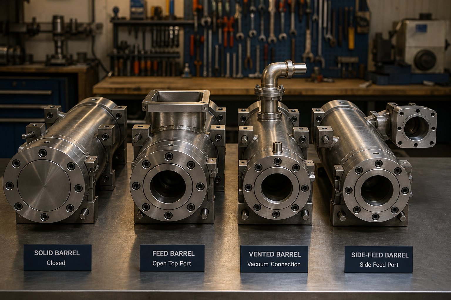
What makes this modularity so powerful is that each barrel section serves a specific function. You are not just adding length - you are adding capability. Here are the standard barrel section types you will encounter on virtually every corotating platform:
- Closed (solid) barrel sections: These have no openings and represent the majority of the process length. They sit at high-pressure locations - melting zones, mixing zones, and the metering section leading to the die - where the melt must be fully contained. Their interior surface takes the full brunt of abrasive and corrosive contact with the polymer.
- Feed barrel sections (open top): An opening in the top allows material to enter from the gravimetric feeder. The feed barrel is always positioned at the upstream start of the process section and typically features a larger bore or wear-resistant insert at the opening to handle the impact of falling pellets.
- Vented barrel sections (atmospheric and vacuum): These have ports machined into the top to allow moisture, solvents, and volatile byproducts to escape the melt. Atmospheric vents simply open to the environment, while vacuum vents connect to a pump that draws negative pressure - commonly 50 to 200 mbar absolute - for deeper volatile extraction. The positioning of vent sections along the barrel determines how many devolatilization stages the process can support.
- Side-feed barrel sections: An opening on the side accommodates a side stuffer - a smaller corotating twin screw auger that pushes fillers, reinforcements, or secondary polymers into the melt stream downstream of the primary feed. Side-feed barrels are essential for masterbatch production and any formulation where additives should bypass the high-shear melting zone to avoid degradation or excessive particle attrition.
Imagine you are running a general-purpose compounding line at 40:1 L/D with one vent port and no side feeders. A new customer requests a heavily filled CaCO3 masterbatch that needs downstream filler addition plus vacuum devolatilization. Instead of purchasing an entirely new machine, you unbolt the existing barrel sections, insert a side-feed barrel after the melting zone, replace a closed section further downstream with a vented barrel, and re-bolt the assembly. The screw elements inside are reconfigured to match. Same motor, same gearbox, same controls - fundamentally different process. That is the real value of modular extrusion barrels.
Process length also matters. A system requiring only basic melting and mixing might run comfortably at 20:1 L/D, while a complex reactive extrusion process with multiple injection points, reaction zones, and multistage devolatilization could require 48:1 L/D or more. Some advanced configurations even link tandem extrusion systems - a twin screw extruder for intensive mixing mated to a single screw extruder for cooling and pumping - to resolve conflicting unit operations that cannot coexist within a single barrel length.
Barrel Metallurgy and Wear Protection
Here is a reality that every compounder eventually confronts: the barrel wears out. It wears slowly and invisibly, but it wears - and the rate depends entirely on what you are processing. Running unfilled polyolefins? A properly hardened twin screw barrel might last years with minimal bore enlargement. Processing 40% glass-fiber-filled polyamide or pushing high-calcium-carbonate-loaded masterbatch through the machine shift after shift? The abrasive filler particles act like liquid sandpaper, grinding against the barrel bore with every screw revolution. As the flight-to-bore clearance opens beyond its original specification - roughly the screw diameter divided by 1,000, per side - melt begins leaking backward over the flights, output drops, melt temperature climbs, and product consistency deteriorates.
Corrosive polymers add a second attack vector. Processing PVC releases hydrochloric acid at elevated temperatures. Fluoropolymers generate hydrofluoric acid. Halogenated flame retardants produce aggressive chemical species that pit unprotected steel surfaces from the inside. In these environments, even a barrel with excellent abrasion resistance can fail prematurely if its metallurgy does not account for chemical attack.
Understanding the threat profile of your specific application is the first step in selecting the right barrel protection strategy:
- Nitrided steel: The baseline for general-purpose, non-filled polymer processing. Gas nitriding creates a hard surface layer (typically 900-1100 HV) that resists moderate abrasion. Cost-effective, but the hardened depth is less than 1 mm - once it wears through, the softer base steel beneath erodes rapidly.
- Bimetallic barrel liners: A thick, wear-resistant alloy liner is centrifugally cast into the barrel bore, providing a much deeper protective layer than surface nitriding alone. Different liner alloys target different threats - iron-based alloys with tungsten carbide particles for maximum abrasion resistance in glass-fiber compounding, nickel-based alloys for corrosion resistance in PVC or fluoropolymer applications, and balanced alloys for environments facing both abrasion and chemical attack simultaneously. Industry practice specifies nickel-based alloys for increased corrosion resistance and powdered metallurgy (PM) compositions for increased abrasion resistance, selecting the liner chemistry to match the specific degradation mechanism at work.
- Powder metallurgy (PM-HIP) liners: Hot isostatic pressing produces ultra-dense, uniformly distributed carbide structures within the liner material. These liners deliver the highest wear resistance available for extremely abrasive formulations - think 60% mineral filler or recycled material streams loaded with contaminants.
- Corrosion-resistant alloy barrels: For processing halogenated polymers or formulations that generate acidic byproducts, the entire barrel or its liner may be specified in a nickel-chromium-molybdenum alloy that resists chemical attack at processing temperatures exceeding 200 degrees Celsius. A chemical-resistant extrusion machine built with this level of metallurgical protection can process aggressive chemistries that would destroy a standard nitrided barrel within weeks.
Selecting the right protection matters enormously for total cost of ownership. A nitrided barrel running glass-fiber-filled compounds might need replacement every 6 to 12 months. The same machine fitted with a bimetallic or PM-HIP liner can run three to five times longer before the bore goes out of tolerance - turning what looks like a higher upfront cost into a dramatically lower cost per operating hour. For compounding producers, masterbatch manufacturers, recycling plants, and pelletizing operations needing replacement or custom twin screw and barrel assemblies, suppliers like NANHAIYA offer parallel twin screw barrels engineered for high-wear and chemical-resistant applications, providing metallurgical options matched to specific processing demands.
Heating and Cooling System Design
Every barrel section must heat up quickly to reach processing temperatures, hold those temperatures precisely during production, and cool down rapidly when viscous dissipation from the screw elements drives the zone hotter than the set point. The hardware that accomplishes this has evolved considerably, and the design choices directly affect process stability.
Barrel heating on modern corotating twin screw extruders relies on one of two primary methods. Cartridge heaters - cylindrical resistance elements inserted into bored holes within the barrel wall - became the industry standard from the 1990s onward because they deliver higher watt density per unit area than older band heater designs, transfer heat more efficiently through direct metal-to-metal contact, and are simpler to replace during maintenance. Band heaters (also called clamp heaters) wrap around the barrel's exterior and are still found on older or smaller machines. They heat more slowly and less uniformly, which can create localized hot spots - a concern when processing heat-sensitive formulations where a 5-degree temperature variation could mean the difference between prime product and degraded scrap.
Cooling is equally critical, and arguably more challenging. In the melting and mixing zones of a heavily loaded compounding run, kneading blocks can generate so much frictional heat that the barrel temperature overshoots the set point even with heaters turned off entirely. The barrel's cooling system must absorb that excess energy quickly enough to prevent thermal runaway.
Two cooling approaches dominate:
- Internal liquid cooling bores: Channels drilled close to the barrel liner carry water or oil in a closed loop. Because the cooling medium flows through the barrel wall itself, heat transfer is fast and responsive. State-of-the-art barrel designs position internal cooling bores as close to the liner as possible for maximum cooling effect, and some configurations incorporate two inlets and two outlets per barrel section to double the flow rate and improve heat extraction. This is the preferred design for high-speed, high-power machines where viscous dissipation generates significant excess heat.
- Forced-air cooling: External blowers direct ambient air over the barrel surface. Simpler and cheaper than liquid cooling, but far less responsive - air removes heat at a fraction of the rate water does. Forced-air cooling was the original TSE cooling method in the 1950s and 1960s, when screw speeds were much lower and less mechanical energy entered the melt. It remains adequate for low-speed counter-rotating machines but is rarely sufficient for modern corotating extruders running at 600 RPM or above.
Why does thermal response speed matter so much? Because every corotating twin screw extruder operates in a dynamic thermal balance between barrel heater input, barrel cooling extraction, and viscous dissipation from the screws. When an operator increases screw speed to intensify mixing, viscous dissipation jumps immediately - but if the cooling system responds slowly, the melt temperature spikes before the PID controller can compensate. That spike may last only seconds, but for a shear-sensitive polymer or a pharmaceutical formulation with narrow thermal stability windows, a few seconds of overheating is enough to generate degradation, crosslinking, or out-of-spec product.
Rapid thermal response also enables tighter temperature profiles during grade transitions. Switching from a high-temperature engineering polymer to a lower-temperature polyolefin compound means the barrel must cool down quickly and stabilize. Machines with high-capacity internal cooling bores accomplish this in minutes; machines relying on external air cooling may take significantly longer, adding transition time and scrap to every product changeover.
The barrel, in short, is not just a container - it is an active thermal management system, a structural framework for modular process design, and a wear surface that must survive hundreds of millions of screw revolutions in contact with abrasive, corrosive materials. Its metallurgy, its modularity, and its heating and cooling hardware all shape what a corotating twin screw extruder can accomplish in practice. Getting the barrel right protects every investment made in screw elements, motor power, and process development.
With barrel design establishing the physical and thermal boundaries of the process, the question shifts from how the machine is built to what it can actually produce. The range of industries and applications served by these extruders is remarkably broad - and each application demands its own combination of screw profile, barrel configuration, and operating strategy.
Industrial Applications Across Compounding, Recycling, and Beyond
A corotating twin screw extruder is not built for one job - it is built for whichever job you configure it to do. The same machine that compounds glass-fiber-filled nylon for automotive parts on Monday can be reconfigured to produce color masterbatch on Tuesday and reprocess post-industrial scrap on Wednesday. That versatility is not theoretical. It is the direct result of modular barrel sections, interchangeable screw elements, and the self-wiping geometry that prevents cross-contamination between runs. Every industry discussed below exploits these features differently, but all of them rely on the same underlying platform.
Plastics Compounding and Masterbatch Production
Compounding is the heartland of corotating twin screw extrusion. Nearly every engineered plastic compound - from carbon-black-filled conductive resins to impact-modified polypropylene blends - passes through one of these machines at some stage of its manufacturing chain. The reason is straightforward: no other continuous processing device offers the combination of intensive mixing, precise residence time control, and modular configurability that compounding formulations demand.
Color masterbatch production illustrates the challenge particularly well. Imagine you need to disperse an organic pigment at 40% loading into a polyethylene carrier resin and produce pellets with zero visible specks, perfect color consistency, and no thermal degradation. That requires breaking pigment agglomerates down to primary particle size (dispersive mixing), spreading those particles uniformly throughout the matrix (distributive mixing), removing entrained air so pellets are dense and nonporous (devolatilization), and doing all of this without overheating a polymer that yellows above a narrow temperature ceiling.
Coperion's technical guidance on masterbatch compounding highlights that no more than about 15% of a color pigment powder should enter the main feed of the extruder to prevent feed-intake problems caused by aeration and fluidization. For loadings above 20% - and masterbatch formulations routinely reach 60% to 80% - split feeding between the main hopper and one or more downstream side stuffers is essential. The polymer melts in the upstream kneading zone, and pigment is introduced into the already-molten stream through side-feed barrel sections, bypassing the high-shear melting zone entirely. This sequencing prevents the powder from blocking the feed throat and ensures proper wet-out of each pigment particle by the polymer melt before downstream mixing elements distribute it uniformly.
Additive concentrates and filled compounds follow similar logic but emphasize different screw element choices. High-loading mineral fillers like calcium carbonate and talc benefit from toothed mixing elements that deliver strong distributive mixing without the extreme shear peaks of 90-degree kneading blocks - which would grind filler particles into problematic fines that spike viscosity. Polymer blends, on the other hand, often need a more aggressive dispersive section to reduce the dispersed-phase droplet size below a critical threshold for acceptable mechanical properties.
Specific application examples within plastics compounding and masterbatch include:
- Color masterbatch with organic and inorganic pigments at loadings from 20% to 80%
- Additive concentrates for UV stabilizers, antioxidants, flame retardants, and slip agents
- Mineral-filled compounds using calcium carbonate, talc, or barium sulfate at high loading levels
- Glass-fiber-reinforced engineering plastics (PA, PBT, PPS) with fiber lengths preserved through gentle downstream feeding
- Polymer blends and alloys (PC/ABS, PP/EPDM, PA/PPO) requiring controlled morphology development
- Co extruded and co-extrusions products where the base compound must meet tight property tolerances before entering a multilayer die
In many of these scenarios, the compound produced on the twin screw extruder feeds directly into downstream processes - film lines, injection molding machines, or coextrusion profile dies - where any inconsistency in dispersion or melt quality amplifies into visible defects in the finished part.
Polymer Recycling and Pelletizing Operations
Recycling is an application where the corotating twin screw extruder's strengths align perfectly with the process demands - and where its limitations must be honestly acknowledged. Post-industrial regrind and post-consumer waste both present challenges that differ sharply from virgin compounding, and understanding those differences is key to deploying TSE technology effectively.
Post-industrial recycling (PIR) is the more natural fit. Edge trim from film and sheet lines, startup purge material, and off-spec production runs are relatively clean, well-characterized feedstocks. A twin screw extruder reprocesses them by melting the regrind, removing residual moisture and volatiles through vacuum venting, optionally blending in virgin resin or additives to restore properties, and pelletizing the output for reuse. PET and PLA edge-trim reclaim systems represent one of the most widely proven PIR applications - the TSE devolatilizes moisture from undried trim to avoid the cost of a separate drying step and minimizes IV loss from hydrolysis, allowing higher percentages of recycled trim to be integrated back into the sheet without compromising mechanical performance.
Post-consumer recycling (PCR) is more complex. Washed and sorted PCR feedstocks still carry residual contaminants - trace polymers from mixed-stream collection, adhesives, inks, odor-causing volatiles, and fine particulates that elude even thorough washing. The corotating extruder's intensive mixing capability disperses trace contaminant polymers into the matrix, and multistage vacuum devolatilization strips residual moisture left from the washing step along with volatile organic compounds that would otherwise cause odor or surface defects in molded parts. However, the tight geometric tolerances inherent in intermeshing TSEs make them vulnerable to hard contaminants like metal fragments or glass shards that can damage screws and barrels. Robust upstream contaminant detection and removal - magnetic separators, metal detectors, and melt filtration systems - are non-negotiable when processing PCR on a twin screw platform.
Specific recycling and pelletizing applications include:
- PET and PLA edge-trim reclaim with inline devolatilization, feeding directly back into a sheet or film line
- Nylon fiber reclaim from bales, using crammer feeders and multistage venting to handle low-bulk-density fluff
- Post-consumer HDPE and PP compounding with high filler loadings (up to 80%) to produce structural products like decking and pallets
- Ground tire rubber processing with EVA for flooring, profiles, and co extruded sheet products
- Recycled PVB recovery from automotive windshield safety glass through tandem TSE devolatilization and compounding
- Intentional degradation of fractional-melt HDPE scrap at high screw speeds to modify MFI for injection molding reuse
A key insight from recycling practitioners: the TSE excels at mixing and devolatilization but is not a high-pressure pump. Melt filtration - essential for removing solid contaminants from PCR streams - requires elevated pressures that often exceed what the extruder screws alone can generate. Gear pumps or single-screw discharge sections are commonly mated to the TSE's output to build and stabilize the pressure needed for fine-mesh screen changers. This tandem arrangement lets each device do what it does best: the twin screw extruder mixes and degasses, while the gear pump or single screw handles pressurization and filtration.
Reactive Extrusion, Food, and Pharmaceutical Processing
Beyond traditional plastics, the corotating twin screw extruder has carved out critical roles in industries where precise thermal and mechanical control during a chemical or physical transformation is essential. These applications leverage the same self-wiping geometry and modular screw configuration that make compounding successful, but they push the technology in directions that pure compounding rarely demands.
Reactive extrusion uses the extruder as a continuous chemical reactor. Monomers, initiators, or grafting agents are injected into the melt stream at controlled locations along the barrel, and the screw profile is designed to deliver a specific combination of temperature, shear, and residence time through the reaction zone. Maleic anhydride grafting onto polyolefins, peroxide-initiated crosslinking, and condensation polymerization of polyesters are all routinely performed on corotating platforms. The modular barrel allows engineers to position liquid injection ports, reaction zones, and vacuum vents exactly where the chemistry requires them - and the self-wiping action prevents partially reacted material from stagnating and causing gel formation or runaway side reactions.
Food extrusion represents one of the oldest twin screw applications. Snack foods, breakfast cereals, textured vegetable proteins, and pet food kibble are all shaped and cooked inside corotating extruders. The intense mixing and precise temperature control cook starch-based formulations uniformly, while the modular barrel accommodates water and steam injection, flavor addition, and controlled expansion at the die. Many co extrusions in the food industry - filled snack pillows with a flavored center, for example - rely on corotating twin screw platforms feeding into specialized co extrusion dies that combine two or more texturally distinct streams into a single product.
Pharmaceutical hot-melt extrusion has grown rapidly as a manufacturing method for drug delivery systems. A historical review published in AAPS PharmSciTech documents how TSE processing evolved from its first pharmaceutical application in the 1990s - Rezulin, the first FDA-approved melt-extruded drug product - into a widely adopted platform for producing amorphous solid dispersions that improve the bioavailability of poorly soluble active pharmaceutical ingredients. The short, well-controlled residence time of the TSE (often under 60 seconds) limits heat exposure for thermally sensitive APIs, and the continuous nature of the process aligns with regulatory initiatives encouraging continuous manufacturing and process analytical technology (PAT) integration.
Specific application examples across these sectors include:
- Maleic anhydride grafting onto polypropylene and polyethylene for adhesion-promoting tie layers in co-extrusions and multilayer packaging
- Peroxide-initiated controlled degradation of polypropylene to produce controlled-rheology grades
- Condensation polymerization and chain extension of recycled PET to restore intrinsic viscosity
- Expanded snack foods and breakfast cereals with controlled cell structure and density
- Textured vegetable protein and meat analogues for plant-based food products
- Co extruded pet food kibble with a soft, flavor-filled interior and a crunchy outer shell
- Amorphous solid dispersions for improving oral bioavailability of poorly water-soluble drugs (e.g., Kaletra, Noxafil)
- Implantable drug delivery devices and abuse-deterrent opioid tablets shaped via precision die extrusion
- Transdermal patches and dissolvable oral films manufactured through flat-die extrusion and chill-roll quenching
What unites every application on this list - from a 50,000 kg/h polyolefin compounding line to a 2 kg/h pharmaceutical development extruder - is the same set of core platform advantages. The self-wiping intermeshing geometry eliminates stagnant material and ensures uniform processing history. The modular barrel and screw design lets engineers tailor feed locations, mixing intensity, reaction zones, and vent placements to each formulation's unique requirements. And starve-fed operation provides independent control over throughput and energy input that no other continuous mixer matches.
That versatility, however, only delivers its full value when the process developed in the lab can be reliably transferred to a production-scale machine. Scaling up a twin screw extrusion process is not a matter of simply buying a bigger extruder - it requires understanding which parameters hold constant, which ones change, and how to select the right screw and barrel components to withstand the demands of full-scale production.
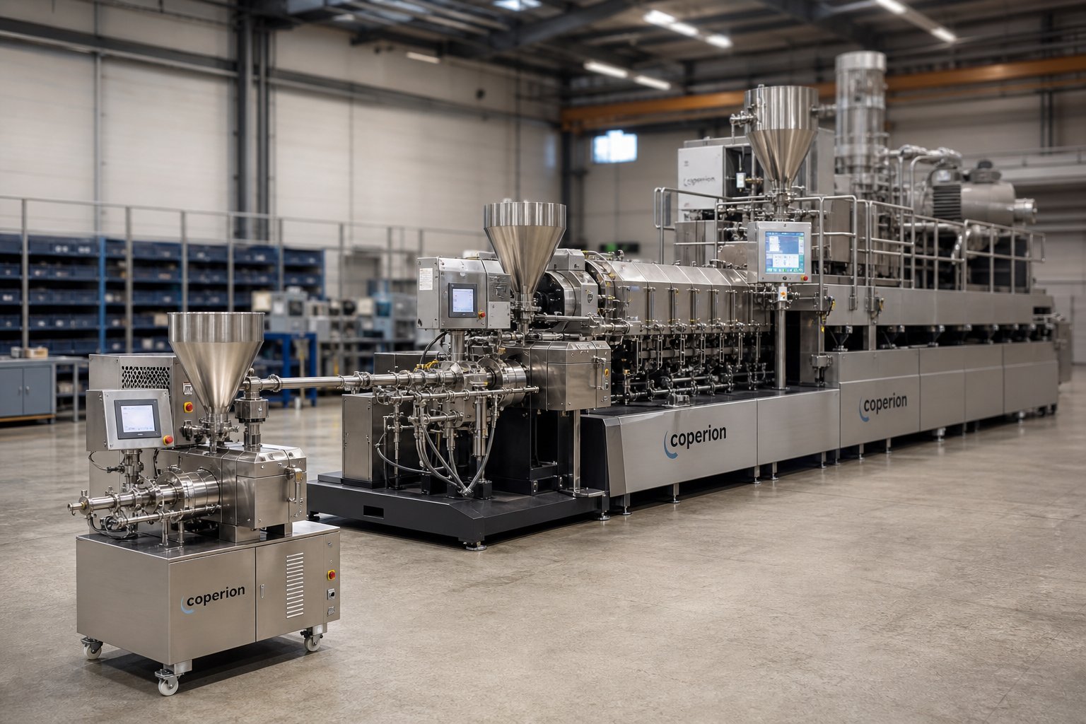
Scaling Up and Selecting the Right Components for Your Process
Developing a flawless process on a laboratory-scale corotating twin screw extruder is satisfying - until you try to reproduce the same product quality on a production machine three or four times the diameter. Scale-up is where elegant lab results collide with industrial reality. Throughput needs to jump by an order of magnitude or more, motor power and torque demands multiply, and heat transfer behavior shifts in ways that catch even experienced engineers off guard. Understanding the principles that govern this transition - and selecting screw and barrel components that can endure production-level demands - separates successful commercialization from expensive trial-and-error campaigns.
Scale-Up Principles From Lab to Production
The most widely applied scale-up method for corotating twin screw extrusion is the volumetric approach. When the process is limited by available power and free volume rather than by heat transfer through the barrel wall, throughput scales approximately with the cube of the screw diameter ratio. In practical terms, if you developed your formulation on a 26-mm extruder and want to scale to a 40-mm machine, the expected rate increase is roughly (40/26)3, or about 3.6 times. Move to a 92-mm production platform, and the ratio jumps to (92/26)3 - a factor of roughly 44 times the lab-scale rate.
When heat transfer is the limiting factor instead - common with thermally sensitive formulations or very low screw speeds - the maximum rate scales with the square of the diameter ratio rather than the cube. The distinction matters: choosing the wrong scaling rule can lead you to target a rate the larger machine physically cannot sustain without overheating or under-processing the material.
So what stays constant during scale-up, and what changes? Here is the general framework:
- Hold constant: Specific mechanical energy (SME, in kWh/kg), barrel temperature profile, screw tip speed (not RPM - tip speed accounts for the larger circumference of bigger screws), screw configuration geometry (same element sequence and proportional lengths), and degree of fill.
- Allow to change: Absolute throughput (kg/h), motor power (kW), total torque requirement (Nm), and absolute screw RPM (which typically decreases on larger machines to maintain equivalent tip speed).
Among these, maintaining equivalent specific mechanical energy input is the single most reliable scale-up criterion. SME captures the energy per kilogram transferred from the motor through the screws into the compound being processed. Match it across scales, and the material experiences a comparable thermomechanical history regardless of machine size.
Sounds straightforward on paper, but a detailed case study published by Dow Chemical reveals how challenging this can be in practice. Researchers scaled a polyolefin masterbatch process from a 26-mm laboratory extruder (SME of 0.083 kWh/kg) to a 40-mm pilot machine and then to a 92-mm production line. All three machines were co-rotating, fully intermeshing, and geometrically similar - same L/D ratio of 44 and same OD/ID ratio of 1.55. The volumetric scale-up rule predicted the correct throughput at each step. Yet simply transferring the optimized screw design, temperature profile, and screw speed from the smaller machine to the larger one failed at both transitions.
On the 40-mm extruder, the initial attempt produced severe pressure fluctuations and deteriorated product quality. The measured SME was only 0.055 kWh/kg - about 34% lower than the lab-scale reference. Only after modifying the screw design to increase melting and mixing intensity, lowering the temperature profile, and reducing screw speed did the process stabilize. The resulting SME climbed to 0.079 kWh/kg, within 5% of the 26-mm benchmark, and the masterbatch quality recovered.
The jump to 92-mm was even more dramatic. Applying the 40-mm optimized conditions directly yielded an SME of just 0.026 kWh/kg - a staggering 69% below the lab-scale value. The extruder discharged unmelted polymer pellets. Root-cause analysis pointed to a low-viscosity raw material creating a lubricating film on the screw and barrel surfaces, reducing the shear stress the screws could transfer into the compound. This effect was negligible on the small machine but became process-breaking at production scale, where the area-to-volume ratio of the barrel drops dramatically and heat transfer control diminishes. Redesigning the screw and adjusting the feeding configuration raised SME to 0.086 kWh/kg, restoring product quality and achieving the full economically viable throughput rate.
The lesson is unmistakable: scale-up equations give you a starting point, not a guarantee. The area-to-volume ratio decreases with increasing extruder diameter, meaning larger machines lose proportionally more control over barrel-wall heat transfer. Material behaviors that are invisible at 26 mm - lubricating effects, localized fluidization, feeding anomalies - can dominate at 92 mm. Intermediate pilot-scale trials on a 40- or 50-mm machine, guided by SME tracking, dramatically reduce the risk of costly surprises at full production scale. Twin screw extruder manufacturers increasingly offer pilot-line rental programs precisely because their customers have learned this lesson the hard way.
Selecting the Right Screw and Barrel Components
A successful scale-up does not end with matching SME. The production machine must also survive the mechanical and chemical demands of full-scale operation - demands that can be orders of magnitude harsher than anything a lab extruder experiences. Selecting the right metallurgy for screw elements and barrel liners is the final, critical step in translating a lab-proven process into a sustainable production reality.
The guiding principle is simple: match the metallurgy to the threat. Different formulations attack screw and barrel surfaces in fundamentally different ways, and no single material of construction handles every scenario optimally.
- Standard nitrided steel is the baseline choice for processing unfilled or lightly filled polymers - polyolefins, polystyrene, ABS, and similar resins that impose minimal abrasion. Surface hardness in the 900-1100 HV range provides adequate wear life at moderate cost.
- Tungsten carbide coatings or PM-HIP (powder metallurgy, hot isostatic pressing) materials are essential for glass-fiber-reinforced compounds, mineral-filled masterbatches, and any formulation containing hard, angular filler particles. These materials maintain hardness levels above 1200 HV deep into the wear zone, extending component life by a factor of three to five compared to nitrided steel in aggressive abrasion environments.
- Corrosion-resistant alloys - typically nickel-chromium-molybdenum grades - are required for halogenated polymers such as PVC, PVDF, and fluoropolymers, as well as formulations containing flame retardants that release acidic byproducts at processing temperatures. Without chemical protection, even the hardest abrasion-resistant surface will pit and corrode from within.
For operations running co extruders or co extrusion machine setups where multiple extruders feed a single die, each extruder may need different barrel and screw metallurgy depending on its specific resin and additive package. A co extruder processing the adhesive tie layer in a multilayer film, for example, faces different wear and corrosion threats than the machine handling the structural polyamide layer - and specifying the same metallurgy for both would either overspend on one or under-protect the other.
When evaluating replacement or upgrade barrel components from any twin-screw extruder manufacturer, consider these factors systematically:
- Formulation abrasiveness: What fillers, reinforcements, or recycled contaminants will contact the barrel bore? Higher abrasive loads demand harder liner materials.
- Chemical aggressiveness: Does the polymer or any additive release corrosive species at processing temperature? Acidic byproducts require nickel-based or specialty alloy protection.
- Bore dimensional tolerance: What is the current clearance between screw flight tips and the barrel wall? Bore wear beyond the original specification reduces conveying efficiency and increases melt temperature - replacement should occur before quality deterioration becomes visible in the product.
- Thermal management compatibility: Does the replacement barrel section support the same heating and cooling configuration as the original? Internal cooling bore geometry and cartridge heater pocket placement must match the machine's thermal control system to maintain process stability.
- Modularity and dimensional compatibility: Will the replacement section bolt into the existing barrel stack without machining modifications? Flange dimensions, alignment dowel positions, and bore centerline distances must match precisely.
- Supplier engineering support: Can the supplier recommend liner chemistry based on your specific application data, or do they offer only generic options? For compounding producers, masterbatch manufacturers, recycling plants, and pelletizing operations sourcing custom or replacement parallel twin screw barrels, NANHAIYA provides barrels tailored to specific processing demands - including wear-resistant and corrosion-resistant configurations matched to the formulation's threat profile.
Getting metallurgy right is not a one-time decision. As product portfolios evolve and recycled content percentages climb, the wear and corrosion demands on barrel and screw components shift accordingly. A barrel liner that lasted three years running virgin polyethylene may wear out in nine months when the same line switches to 30% post-consumer recycled content loaded with inorganic contaminants. Periodic bore measurement and proactive component replacement - guided by the specific abrasion and corrosion characteristics of the current product mix - protect throughput, product quality, and the substantial capital investment represented by every production-scale corotating twin screw extruder on the plant floor.
Frequently Asked Questions About Corotating Twin Screw Extruders
1. What is the difference between a corotating and counter-rotating twin screw extruder?
A corotating twin screw extruder has both screws spinning in the same direction, pulling material through the intermeshing zone to deliver excellent dispersive and distributive mixing with full self-wiping capability. A counter-rotating design turns screws in opposite directions, squeezing material in a calendering action that builds high pressure but provides lower mixing intensity. Corotating machines dominate compounding, masterbatch, and reactive extrusion, while counter-rotating variants — including conical twin screw extruders — are preferred for rigid PVC pipe and profile extrusion where gentle shear and high die pressure matter most.
2. How does the self-wiping mechanism work in a corotating twin screw extruder?
In a corotating design, the flight tip of one screw continuously sweeps the root diameter of the adjacent screw with every rotation. Because both screws turn in the same direction, surface velocities at the intermesh point move in opposite directions, creating a scraping effect that removes material from all metal surfaces within a single revolution. This eliminates stagnant polymer that would otherwise degrade into black specks or gels, ensures a narrow residence time distribution for consistent product quality, and dramatically speeds up color and material changeovers by preventing buildup in dead zones.
3. What does the OD/ID ratio mean for twin screw extruder performance?
The OD/ID ratio — outer diameter divided by inner (root) diameter of the screw — determines the balance between free volume and torque capacity. A higher OD/ID ratio (e.g., 1.66/1) provides deeper screw channels and more free volume for material processing, but requires advanced shaft designs to maintain adequate torque transmission. Modern machines achieve OD/ID ratios of 1.66/1 or above using asymmetrical splined shafts, delivering torque densities around 18 Nm/cm³. This allows processors to compound high-viscosity or heavily filled materials at moderate screw speeds without overloading the drive system.
4. How do you scale up a twin screw extrusion process from lab to production?
The most reliable scale-up method uses volumetric scaling, where throughput increases approximately with the cube of the screw diameter ratio when power and free volume are limiting factors. The critical metric to hold constant across scales is specific mechanical energy (SME, measured in kWh/kg), which captures the thermomechanical history the material experiences. Barrel temperature profile and screw tip speed should also remain equivalent. However, scale-up equations provide starting points, not guarantees — intermediate pilot trials on a 40- to 50-mm machine guided by SME tracking are strongly recommended to identify material behaviors that only emerge at larger diameters.
5. What barrel liner materials are best for abrasive or corrosive twin screw extrusion applications?
Barrel liner selection depends on the specific wear mechanism. Nitrided steel (900-1100 HV) suits unfilled polymer processing at moderate cost. Bimetallic liners with tungsten carbide particles or PM-HIP (powder metallurgy, hot isostatic pressing) materials handle highly abrasive fillers like glass fiber and calcium carbonate, extending barrel life three to five times over nitrided steel. For halogenated polymers such as PVC or fluoropolymers that release corrosive acids, nickel-chromium-molybdenum alloy liners resist chemical attack at processing temperatures. Suppliers like NANHAIYA offer custom parallel twin screw barrels with metallurgy matched to specific formulation demands, serving compounding, masterbatch, recycling, and pelletizing operations.
Written by
Nanhaiya Technical Team
Zhoushan Nanhaiya Plastic Machinery Co., Ltd.
The Nanhaiya technical team supports screw and barrel manufacturing projects through application review, technical communication, custom manufacturing coordination, and production and quality control.
Discuss Your Application
Related Articles
More insights on screw barrel technology and plastics processing.
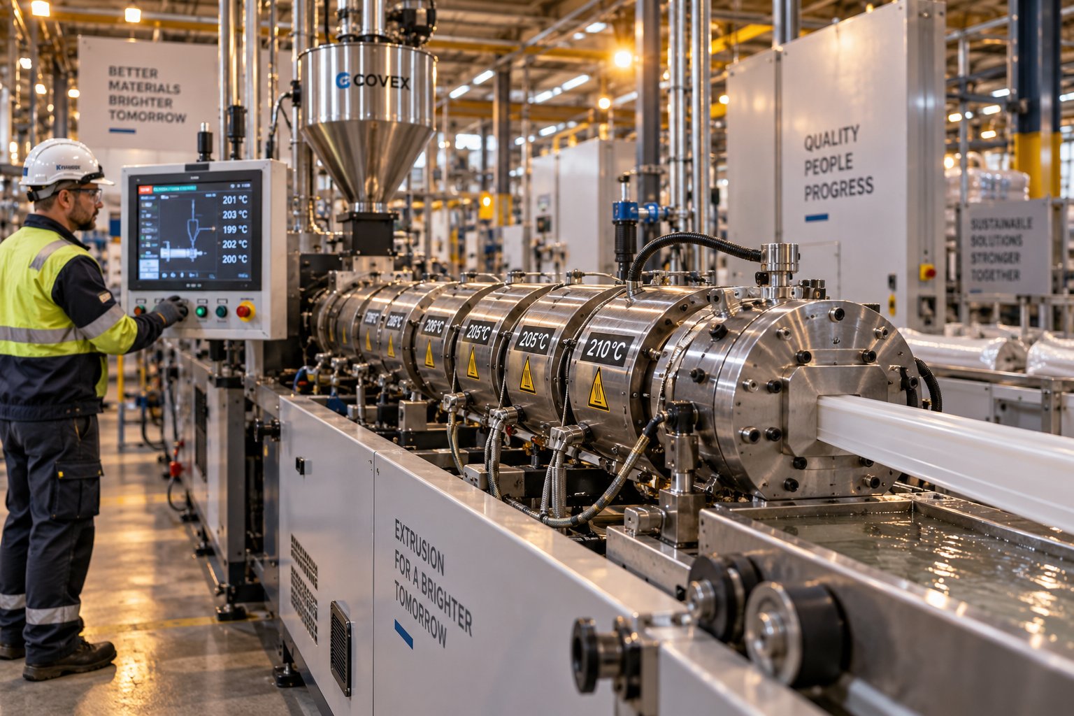
Plastic Extrusion Troubleshooting: Trace Every Defect to Its Source
Oct 16, 2026
Master plastic extrusion troubleshooting with this symptom-first guide. Diagnose defects zone by zone, fix root causes, and prevent recurring issues fast.
Read Article
PVC Profile Extrusion Line Decoded: From Screw Design to Factory Floor
Oct 16, 2026
Learn how a PVC profile extrusion line works — from screw design and barrel profiling to troubleshooting, maintenance, and factory layout planning.
Read Article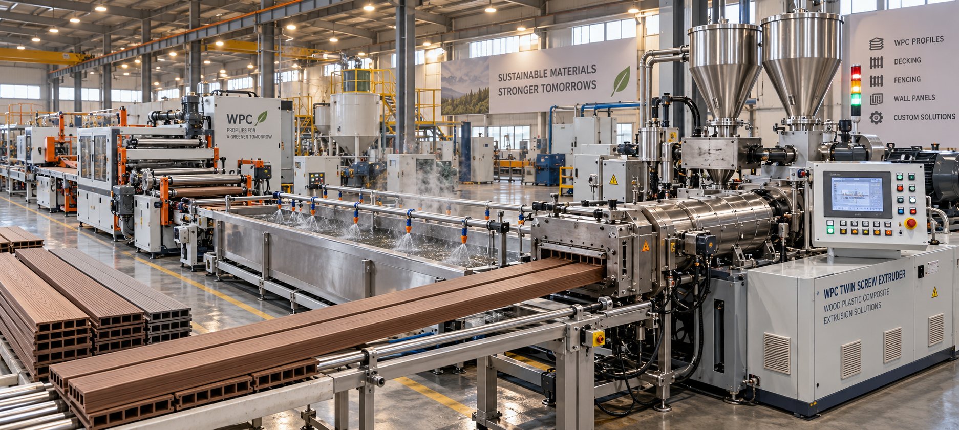
WPC Profile Extrusion Machine Decoded: Raw Blend To Flawless Profile
Oct 15, 2026
Learn how a WPC profile extrusion machine works — from extruder types and temperature zones to troubleshooting, wear management, and emerging co-extrusion trends.
Read ArticleLooking for something else?
Search by material, symptom or product and jump straight to the relevant page.
These are navigation suggestions based on keyword matching — not a quotation, not a delivery commitment, and not a substitute for engineering review. Final specification is confirmed by our engineers against your drawings and processed material.
Need help with screw barrel selection?
Share your machine model, processed material and application. Our team can help with pricing and technical support.