

What Is a Co-Rotating Twin Screw Extruder and Why It Matters
Imagine two tightly intermeshed screws spinning side by side in the same direction, each one continuously sweeping material off the other's surface. That single kinematic detail — same-direction rotation — unlocks a set of processing capabilities that no other extruder architecture can match.
Defining the Co-Rotating Twin Screw Extruder
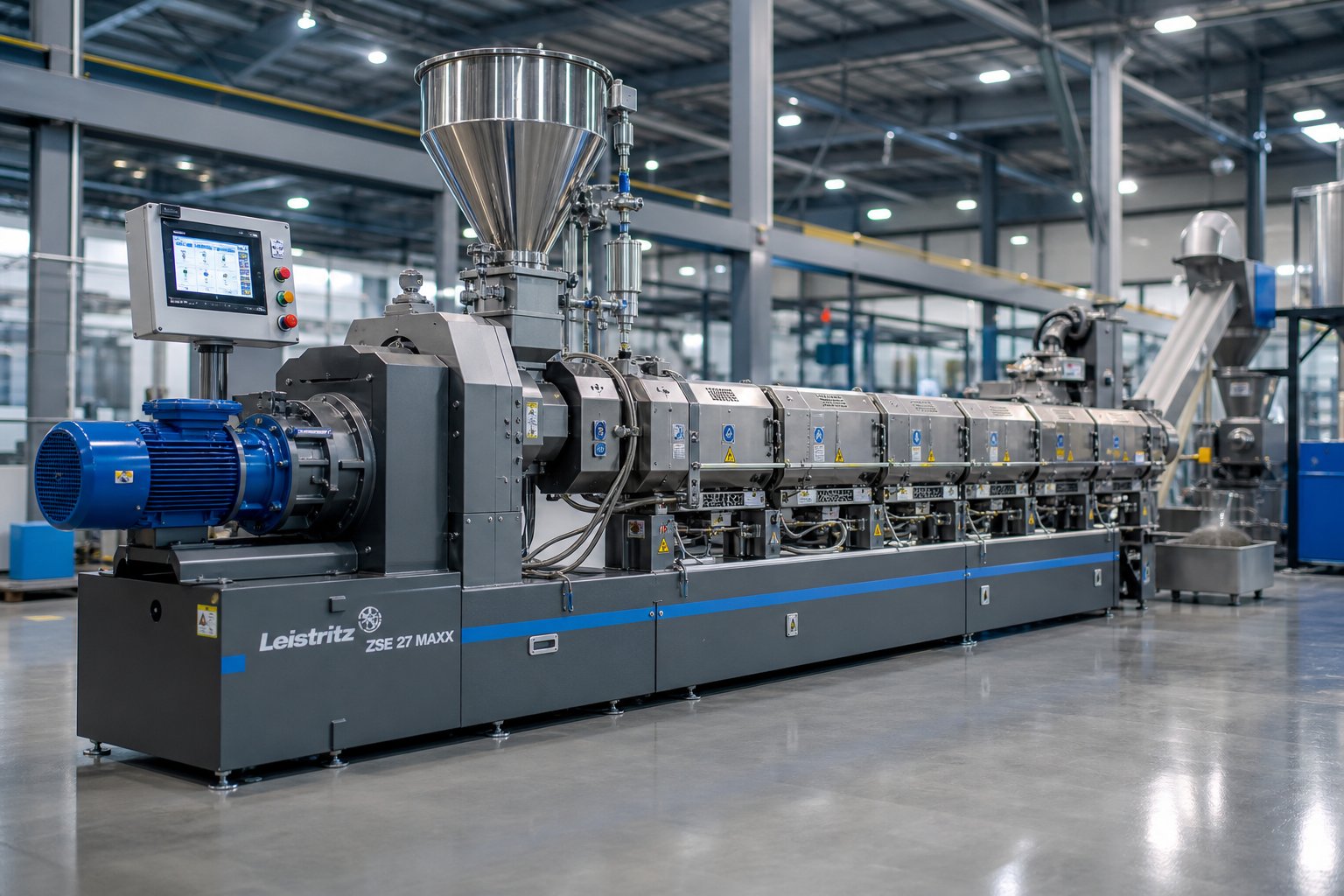
A co-rotating twin screw extruder is a modular processing machine in which two parallel, intermeshing screws rotate in the same direction inside a segmented barrel. It is engineered for intensive mixing, compounding, devolatilization, and reactive processing of polymers and other materials, and its self-wiping geometry virtually eliminates material stagnation.
That self-wiping behavior is the sharpest line separating this machine from its alternatives. In a single-screw extruder, the material relies almost entirely on barrel-wall friction for forward transport, offering limited mixing control. A counter-rotating twin screw extruder draws material into a calendering gap between the screws — useful for low-shear forming of heat-sensitive compounds like rigid PVC — yet it cannot match the thorough channel cleaning a co-rotating design delivers. The flight of one screw physically sweeps the channel of the other, pushing melt forward and preventing dead zones where degradation could begin.
Why This Technology Dominates Modern Compounding
Three characteristics explain why the co-rotating twin-screw extruder has become the default platform for polymer compounding worldwide. First, its modular screw and barrel construction lets engineers reconfigure the machine for entirely different processes — from glass-fiber reinforcement to reactive grafting — without purchasing new equipment. Second, starve-fed operation decouples throughput from screw speed, giving operators independent control over mixing intensity and production rate. Third, the intense yet tunable shear fields produced between intermeshing screws and between screw and barrel enable both dispersive breakup of filler agglomerates and distributive blending of polymer phases.
Most technical resources describe these advantages as a feature list. This article takes a different path. In the sections ahead, you'll explore the process-engineering reasoning behind each design choice — from the kinematics that make self-wiping possible to the six distinct processing zones that most engineers compress into an oversimplified three-stage model. Understanding the why behind the hardware is what separates routine operation from true process mastery.
Self-Wiping Geometry and Intermeshing Principles Explained
Self-wiping sounds straightforward — one screw cleans the other. But why does same-direction rotation produce a true wiping action while opposite-direction rotation does not? The answer lies in the path each screw flight traces relative to its neighbor, and it is a distinction that directly shapes residence time, mixing uniformity, and product quality in every twin screw extruder on the plant floor.
The Kinematic Principle Behind Self-Wiping
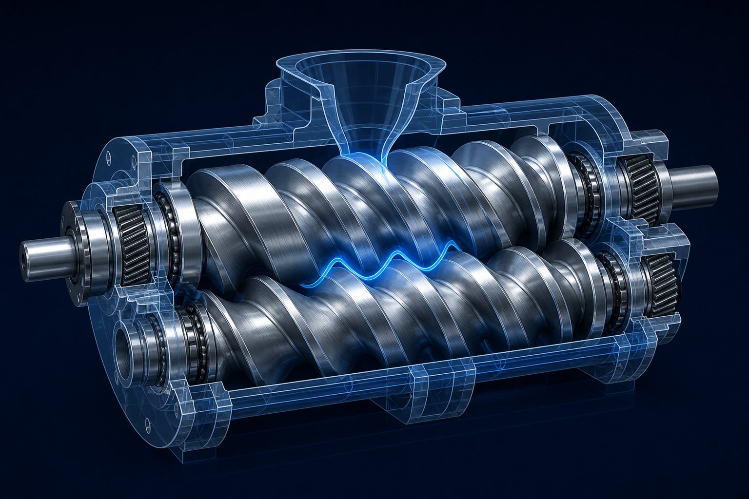
Picture two fully intermeshing screws turning in the same direction. As the flight tip of one screw passes through the channel of the other, it travels along the root of that channel in a sweeping arc. This motion physically pushes material out of the channel, transfers it to the adjacent screw, and prevents any polymer from riding along with a single screw indefinitely. The result is a continuous handoff: material is forcibly transferred to the next flight at the intermeshing region, keeping the entire internal volume in constant motion.
In a counter-rotating arrangement, the geometry works differently. The two screws meet at the top — a region often called the calendering gap — where material is drawn inward and compressed between the approaching flights. This compressive, calender-roll-like action can disperse additives effectively under gentle conditions. However, it does not produce the same sweeping arc across the opposing channel. Material can become partially trapped in the converging gap, and the self-cleaning effect is notably weaker. That is why counter-rotating twin screw extruders tend to operate at higher fill levels and lower speeds, relying on the calendering effect rather than wiping for material transport.
Why does this matter in practice? A true self-wiping action keeps the residence time distribution narrow, meaning every particle of material spends roughly the same amount of time inside the barrel. Narrow residence time distribution is critical for reactive extrusion, heat-sensitive polymers, and any process where thermal history must be tightly controlled. Stagnant pockets lead to degradation, gels, and off-color specs — all problems that self-wiping geometry is specifically designed to eliminate.
Intermeshing vs Non-Intermeshing Configurations
Not all twin-screw extruders rely on the same degree of screw engagement. Even within co-rotating designs, the choice between fully intermeshing and non-intermeshing configurations creates significant processing differences.
In a fully intermeshing co-rotating setup, the flight of one screw fits tightly into the channel of the other, with minimal clearance between the flight tip and the opposing screw root. This tight engagement delivers positive conveying — material cannot slip backward easily — and the self-wiping action is at its strongest. You'll notice that virtually all modern compounding twin screw extruders use this configuration because it offers the best combination of mixing intensity, narrow residence time distribution, and process control.
A non-intermeshing co-rotating design, by contrast, positions the two screws parallel to each other with a gap between them. The screws do not engage, so there is no wiping action and no forced material transfer between channels. This layout offers more open free volume and lower shear intensity, which can suit thermally sensitive or low-viscosity materials. However, mixing efficiency is moderate, and the absence of self-cleaning means that material buildup inside the barrel becomes a genuine concern over long production runs.
There is also a middle ground — partially intermeshing designs — where the screws engage only over part of their geometry with larger clearances. These offer reduced shear compared to fully intermeshing screws while still retaining some degree of material transfer. They appear most often in specialty counter-rotating systems or formulations where a balance between dispersion and material protection is required.
Co-Rotating vs Counter-Rotating Geometry Compared
When engineers evaluate co-rotating and counter-rotating twin screw extruder configurations side by side, the differences extend well beyond rotation direction. The table below maps three common configurations against the attributes that matter most for process design:
| Attribute | Co-Rotating Intermeshing | Co-Rotating Non-Intermeshing | Counter-Rotating Intermeshing |
|---|---|---|---|
| Self-Wiping Ability | Excellent — continuous flight-to-channel sweeping eliminates dead zones | None — screws do not engage | Limited — calendering gap provides compression but not true channel wiping |
| Residence Time Distribution | Narrow and well-controlled | Broad — material can bypass or stagnate | Moderate — high fill operation narrows distribution but pockets remain |
| Pressure Generation | Moderate — typically requires die-end pressure buildup elements | Low | High — gear-pump-like calendering action builds pressure effectively |
| Shear Intensity | High and tunable via screw element selection | Low | Low to moderate — suited to shear-sensitive materials |
| Typical Applications | Polymer compounding, masterbatch, reactive extrusion, recycling | Gentle blending of heat-sensitive or low-viscosity compounds | Rigid PVC pipes, sheets, and profile extrusion; formulations requiring minimal shear heating |
A few patterns stand out. Co-rotating intermeshing twin-screw extruders dominate whenever mixing intensity, process flexibility, or thermal-history control is the priority. Counter-rotating intermeshing machines carve out a clear niche for materials like rigid PVC, where the extrusion temperature must be held low and the calendering effect provides just the right level of gentle dispersion. Non-intermeshing designs serve a narrower set of applications where minimal shear and open volume outweigh the need for self-cleaning.
What truly sets the co-rotating intermeshing platform apart, though, is not any single attribute — it is the modularity behind it. The ability to swap screw elements along a splined shaft means engineers can reconfigure shear, mixing, and pressure profiles zone by zone. That modular element design is precisely what transforms a pair of spinning screws into a fully programmable processing platform.
Six Processing Zones from Feed Throat to Die
That modular, zone-by-zone reconfigurability raises an obvious question: what exactly are the zones? Most textbooks and equipment manuals describe twin screw extrusion with a simple three-stage model — feeding, melting, and metering. While convenient, that model glosses over critical transitions where process outcomes are actually decided. A more accurate picture breaks the barrel into six distinct processing zones, each with its own fill level, shear profile, and residence time characteristics.
When you trace the path of a polymer pellet from the feed throat to the die face, you'll notice that it passes through fundamentally different mechanical and thermal environments. Understanding these environments is what allows engineers to configure screw elements, barrel temperatures, and vent placements with real precision rather than guesswork.
Solids Conveying and Melting Zones
The first two zones handle the transformation from loose solid feedstock to a coherent melt — a transition that sets the foundation for everything downstream.
- Solids Conveying Zone — Raw material enters through the feed throat, typically metered by a gravimetric feeder rather than gravity-flooded into the barrel. Large-pitch, deep-flighted conveying elements transport pellets, powder, or flakes forward without compressing them aggressively. Fill level in this zone is intentionally low — often below 30% of the available channel volume — because starve-fed operation keeps the degree of fill well below maximum conveying capacity. Shear intensity is minimal, and the primary objective is stable, consistent transport toward the melting region. Barrel temperatures here are typically set below the polymer's melting point, or even left unheated, to prevent premature softening that could disrupt solid conveying.
- Melting/Plastication Zone — As material advances, a combination of barrel heat and mechanical shear from narrower-pitch elements and initial kneading blocks converts solid particles into a viscous melt. Shear intensity rises sharply in this zone. Kneading blocks and shearing elements enhance plasticization, while shallower screw grooves improve heat exchange between the melt and barrel wall. Fill level climbs as the polymer transitions from a compressible solid to an incompressible liquid, and residence time per unit length increases. Barrel temperatures in this zone typically range from 150 °C to 280 °C — though high-performance engineering plastics may demand settings approaching 400 °C or above. Getting this zone right is critical: incomplete melting here creates unmelted particles that persist through every downstream stage.
Mixing and Devolatilization Zones
With the polymer fully molten, the next two zones deliver the mixing action and volatile removal that define compound quality in any double screw extruder machine.
- Melt Mixing Zone — This is where the real compounding work happens. Kneading blocks — arranged in forward, neutral, and reverse stagger angles — deliver two types of mixing simultaneously. Dispersive mixing applies high shear stress to break apart filler agglomerates, pigment clusters, or incompatible polymer domains. Distributive mixing reshuffles melt streams to spread those broken-down particles evenly throughout the matrix. Fill level in the mixing zone is high, often approaching 100% in fully filled kneading block sections, because high fill raises shear stress and promotes both dispersive and distributive action. Residence time is longer here than in conveying sections, and shear intensity reaches its peak. Engineers adjust mixing severity by selecting kneading disc width, stagger angle, and the number of kneading blocks in series — a balancing act between adequate dispersion and the risk of excessive viscous heating.
- Melt Conveying/Pumping Zone — After the intensive mixing section, forward-conveying screw elements with standard or reduced pitch stabilize flow and begin rebuilding pressure. This zone acts as a transition — shear intensity drops, fill level moderates, and the melt is transported smoothly toward the next functional section. In some screw configurations, this zone also serves as a thermal relaxation segment, allowing the melt to cool slightly after the high-shear mixing region before entering a devolatilization stage.
Die Pressurization and Output Stability
The final two zones prepare the melt for a clean, consistent exit — one by removing what should not be there, the other by building the pressure needed for uniform die flow.
- Devolatilization Zone — Moisture, trapped air, residual monomers, and low-molecular-weight volatiles are removed here through atmospheric or vacuum venting. The key to effective devolatilization is maximizing the free melt surface exposed to the vent. Large-pitch conveying elements positioned beneath the vent port reduce fill level and expand the exposed surface area, while reverse kneading blocks or left-handed elements placed upstream create a melt seal that prevents backflow into the vent opening. Fill level in this zone is deliberately low — a stark contrast to the fully packed mixing zone just upstream. Residence time is moderate, and shear is kept minimal to avoid re-entraining volatiles into the melt. This zone is one of the most overlooked in the co extrusion process, yet skipping or under-designing it directly degrades product purity and can produce foaming, porosity, or surface defects in the final pellet or part.
- Die Pressurization Zone — The last barrel section before the die employs tight-pitch, shallow-channel conveying elements to compress the melt into a uniform, fully pressurized stream. Fill level reaches 100%, and the melt must be thermally homogeneous to prevent flow imbalances across the die. Barrel temperature is held close to the target processing temperature — too hot and viscosity drops unevenly across the channel; too cold and excessive pressure spikes stress the motor and gearbox. Stable pressure generation here is what ultimately determines pellet uniformity, strand consistency, or sheet thickness tolerance at the die exit.
Across all six zones, a clear pattern emerges: fill level, shear intensity, and residence time are not fixed properties of the machine — they are design variables that engineers control through screw element selection, barrel segment choice, and operating parameters. The table below offers a quick reference for how these three variables shift from feed throat to die:
| Processing Zone | Typical Fill Level | Shear Intensity | Relative Residence Time |
|---|---|---|---|
| 1. Solids Conveying | Low (starve-fed) | Minimal | Short |
| 2. Melting/Plastication | Rising | High | Moderate |
| 3. Melt Mixing | High to fully filled | Peak | Longer |
| 4. Melt Conveying/Pumping | Moderate | Low | Short |
| 5. Devolatilization | Low (by design) | Minimal | Moderate |
| 6. Die Pressurization | Fully filled | Low to moderate | Short |
Recognizing these six zones — rather than collapsing them into three — changes how you approach every screw profile decision. It also reveals why modular element design is so powerful: each zone demands a different element type, and the ability to swap elements along a splined shaft means the same machine can be tuned for vastly different materials and formulations.
Modular Screw Elements That Define Processing Performance
Each of those six processing zones demands its own combination of shear, conveying force, and fill level. So how do engineers actually build those conditions into the machine? The answer is modular screw element design — the single most powerful variable in any twin screw compounding extruder, and the one most frequently underexplained in technical literature.
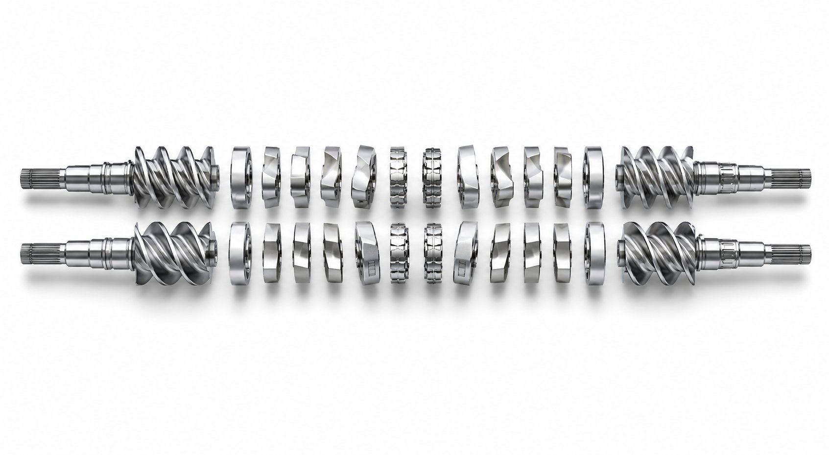
Unlike a single-screw extruder, where the screw is machined as one continuous piece of metal, a co-rotating twin screw extruder uses individual elements that slide onto a common splined shaft. The arrangement of these elements on the shaft depends on the process and material, and no universal gold-standard configuration exists. Every formulation — from calcium-carbonate-filled polyolefin to reactive grafted polyamide — requires its own element sequence. That makes understanding element families the starting point for any serious process engineering effort.
Kneading Blocks and Conveying Elements
All twin screw and barrel configurations draw from a surprisingly small set of element families, each with a distinct mechanical role:
- Forward conveying elements — These are the workhorses of material transport. Deep-flighted, helical elements with standard right-hand pitch push material downstream while generating relatively low shear. Larger pitch means faster conveying and lower fill; smaller pitch increases fill level and pressure buildup. You'll find these in the solids conveying zone, between kneading sections, and immediately before the die.
- Reverse conveying elements — Left-hand pitch elements that push material backward, creating a localized restriction. They build back-pressure, increase fill upstream of their position, and form the melt seals essential for effective devolatilization. A short reverse element before a vacuum vent prevents molten polymer from flowing out through the vent port.
- Kneading blocks — These are the heart of mixing in any compounding twin screw extruder. A kneading block consists of multiple disc-shaped lobes offset at a stagger angle along the shaft. Wider kneading elements promote dispersive mixing, whereas narrow kneading elements contribute toward distributive mixing. The stagger angle is equally important: forward-staggered blocks (typically 30° or 45°) convey material gently while mixing; neutral blocks at 90° provide no conveying effect and maximize residence time and shear; reverse-staggered blocks push material backward, creating intense restriction and the highest shear zones in the entire profile.
- Toothed mixing elements (TME/ZME) — Gear-like elements with teeth that repeatedly split and recombine melt streams. They excel at distributive mixing — spreading additives, pigments, or liquid additives uniformly through the melt — while strictly controlling melt temperature rise. This makes them ideal for color-sensitive masterbatch applications or heat-sensitive polymer blends where kneading blocks alone would generate excessive viscous heating.
The table below maps each element type to its processing function, typical zone placement, and effect on the three critical process variables — shear level, fill, and pressure:
| Element Type | Primary Function | Typical Zone Placement | Shear Level | Effect on Fill | Pressure Change |
|---|---|---|---|---|---|
| Forward Conveying (large pitch) | Rapid material transport; vent exposure | Solids conveying, devolatilization | Low | Low fill | Slight increase |
| Forward Conveying (small pitch) | Pressure buildup; controlled transport | Die pressurization, pre-vent conveying | Low to moderate | High fill | Significant increase |
| Reverse Conveying | Melt seal; back-pressure generation | Upstream of vent ports; end of mixing zone | Moderate | Forces 100% fill upstream | Localized spike |
| Kneading Block — Forward (30-45°) | Moderate mixing with forward conveying | Early melting zone; gentle mixing sections | Medium | Moderate | Slight increase |
| Kneading Block — Neutral (90°) | Maximum mixing intensity; no conveying | Intensive mixing zone | Very high | High (material accumulates) | Neutral |
| Kneading Block — Reverse | Extreme restriction; melt seal creation | End of mixing zone; pre-vent seal | Extreme | Forces 100% fill upstream | Sharp drop downstream |
| Toothed Mixing Element (TME/ZME) | Distributive mixing; low-shear homogenization | After kneading zone; color/additive blending | Low to medium | Moderate | Neutral to slight increase |
How Screw Profile Configuration Drives Outcomes
Imagine laying out a bare splined shaft and building the profile from left to right. In the feed zone, you'd start with large-pitch forward conveying elements — deep channels that accept incoming pellets without compressing them. Transitioning into the melting zone, pitch decreases and the first kneading blocks appear, typically forward-staggered at 30° to 45° to begin shearing the softening polymer. The intensive mixing zone follows with wider kneading blocks at higher stagger angles — 60° or even 90° — stacked in series to deliver the dispersive energy needed to break apart filler agglomerates or blend incompatible polymer phases.
Right after the mixing section, a short reverse element or reverse kneading block creates a melt seal — a fully filled, pressurized plug of polymer that prevents volatiles or air from migrating backward or forward past that point. This melt seal is critical upstream of every vent port, because without it, vacuum applied at the vent would pull molten polymer rather than vapor. Downstream of the seal, large-pitch conveying elements open up free volume beneath the vent to maximize the exposed melt surface area for devolatilization. Finally, the profile closes with tight-pitch conveying elements that rebuild pressure for stable flow through the die.
The beauty of this system is its reversibility. If a formulation change demands gentler mixing — switching from an abrasive glass-fiber compound to a soft thermoplastic elastomer blend, for instance — the engineer simply slides out aggressive kneading blocks and replaces them with lower-angle or narrower elements, all on the same shaft and inside the same barrel.
Modular Barrel Segments and Port Placement
Screw elements only tell half the story. The barrel itself is segmented into individual sections — typically four, five, or six diameters long — and each section can be independently heated and cooled for precise temperature control. More importantly, barrel segments come in several functional configurations:
- Closed barrel sections — Fully enclose the melt on all sides. They provide maximum heat transfer and are used wherever the process requires tight thermal control — through the melting zone, mixing zone, and die pressurization zone.
- Open (vented) barrel sections — Feature a top opening for atmospheric or vacuum venting. Positioned at the devolatilization zone, they allow moisture, air, and volatile byproducts to escape. A preferred practice on extruders with L/D of 40 or greater is to place the vacuum vent two barrel sections upstream of the die, reducing the risk of melt backup into the vent during pressure fluctuations.
- Side-feed barrel sections — Contain a secondary figure-eight bore on the side of the barrel that connects to a twin-screw side stuffer. This allows fillers like glass fiber, calcium carbonate, or carbon black to enter the melt downstream of the primary melting zone — protecting shear-sensitive additives from unnecessary thermal and mechanical exposure.
- Combination (combi) barrels — Integrate a side-feed port with a small upstream atmospheric vent in a single barrel section, allowing entrained air to escape as powder or fiber is stuffed into the melt.
The alignment between barrel segments and screw zones is deliberate. A side-feed barrel must line up with forward conveying elements on the screw so incoming filler is immediately transported into the melt stream rather than accumulating at the feed point. A vent barrel must sit directly above large-pitch, partially filled conveying elements — never above a fully filled kneading block, which would push melt out through the vent opening. Liquid injection ports for oils, coupling agents, or peroxide initiators follow the same logic: they need to meet a partially filled screw section where the liquid can be absorbed into the melt without pooling or flashing off.
This coordinated design of twin screw and barrel segments is what transforms a simple pair of rotating shafts into a fully programmable processing line. Yet the hardware alone doesn't dictate outcomes — the process variables that govern how material moves through these elements are equally decisive, particularly the starve-feeding strategy and specific torque capacity that define the machine's operational envelope.
Process Variables and the Starve-Fed Control Strategy
Modular screw elements and segmented barrels give the machine its physical flexibility — but flexibility without control is just chaos. What actually turns a twin-screw extruder machine into a precision processing platform is the way its key operating variables interact. Two concepts sit at the center of that interaction, yet both are routinely glossed over in equipment brochures and technical manuals: specific torque and starve-fed operation.
What Specific Torque Means and Why It Matters
Every motor has a torque limit. Every polymer compound resists being sheared, conveyed, and pressurized. The question that determines whether your extruder can handle a particular formulation is not simply "how much torque does the drive produce?" — it is how much torque is available per unit of processing volume inside the screw channels.
That ratio is called specific torque, typically expressed as torque per cubic centimeter of free volume in the screw (Nm/cm3). It captures how much energy the machine can transfer into the material per revolution, independent of screw diameter. Two extruders with the same screw size can have dramatically different specific torque ratings depending on gearbox design, motor capacity, and shaft metallurgy — and that difference directly determines which formulations the machine can run.
Here is why this matters in practice:
- High-viscosity compounds — Engineering polymers like PMMA or polycarbonate generate enormous resistance to screw rotation, especially at lower barrel temperatures. Research on a co-rotating twin screw extruder with a 16 mm diameter showed that processing PMMA at 180 °C was not even possible because the screw got stuck and the extruder stopped automatically due to high torque generation. Only at 220 °C and 30 rpm did the operation become stable. A machine with higher specific torque would push that operating window wider, allowing lower temperatures or faster speeds before hitting the motor's torque ceiling.
- High filler loadings — Compounds containing 40% or more of calcium carbonate, glass fiber, or carbon fiber increase melt viscosity significantly. Each additional percentage point of filler demands more torque to convey and mix. If the extruder's specific torque is marginal for the formulation, operators are forced to reduce throughput or raise barrel temperatures to compensate — both of which can degrade product quality.
- Process headroom — A higher specific torque class does not just mean the machine handles tougher materials. It means the process engineer has room to optimize. You can run at lower temperatures to protect heat-sensitive additives, push throughput higher without motor overload, or use more aggressive kneading blocks without worrying about tripping the drive.
Modern high-performance twin-screw extruder machines are classified by their specific torque density — with values ranging from roughly 8 Nm/cm3 on older-generation platforms up to 18 Nm/cm3 or more on current designs. When evaluating any plastic twin screw extruder for a new application, specific torque should be one of the first specifications you check, not an afterthought buried in the machine datasheet.
Starve Feeding vs Flood Feeding Explained
If specific torque defines the energy ceiling of the machine, the feeding strategy determines how material enters and fills the barrel beneath that ceiling. This is where co-rotating twin screw extruders diverge most sharply from conventional single-screw machines.
A single-screw extruder is typically flood-fed: the feed hopper sits directly above the barrel, and gravity fills the screw channel completely. Throughput is dictated by screw speed — spin faster, and more material gets pushed through. The operator has one primary control lever, and changing screw speed simultaneously changes both throughput and the intensity of mechanical work on the material.
A co-rotating twin screw plastic extruder works differently. Material is metered into the feed throat by a gravimetric feeder — a loss-in-weight system that delivers a precisely controlled mass flow rate regardless of what the screws are doing. The screws are never fully filled in the feed zone; they are deliberately starved. This means the rate at which material enters the barrel is completely independent of the screw speed.
Starve-feeding is what transforms the co-rotating twin screw extruder from a simple conveying device into a true process-engineering platform. By decoupling feed rate from screw speed, it gives the operator independent control over throughput and mixing intensity — two variables that flood-fed machines force into a single, inseparable knob.
The practical impact of this decoupling is enormous. Want more mixing energy without increasing output? Raise screw speed while keeping the feeder rate constant — the material spends more time being worked by kneading blocks at a lower fill level. Need higher throughput with less shear? Increase the feed rate and reduce screw speed, filling the channels more fully and pushing material through faster with less mechanical energy input per kilogram. This flexibility is precisely why gravimetric feeding has become a critical area of expertise for compounding operations, with specialized workshops dedicated to feeder selection, configuration, and troubleshooting.
Balancing Screw Speed, Feed Rate, and Temperature
Starve-feeding creates a three-axis control space that no flood-fed machine can replicate:
- Feed rate controls throughput (kg/h) and, along with screw speed, determines the degree of fill inside the barrel.
- Screw speed controls shear rate, residence time, and the intensity of mechanical energy input.
- Barrel temperature profile controls thermal energy input and melt viscosity, influencing both mixing behavior and material degradation risk.
These three variables interact in ways that demand careful balancing. Consider screw speed alone. Increasing rpm raises shear rate, which heats the polymer through viscous dissipation. Research on polypropylene across multiple twin screw extruder sizes — 25 mm, 28 mm, and 45 mm — consistently demonstrates that high rotational speeds, low throughputs, and high melt temperatures lead to greater material degradation, regardless of machine diameter. The chain scissions caused by excessive shear and temperature shift the molar mass distribution toward lower molecular weights, reducing tensile strength and altering rheological behavior.
Experimental data reinforces this pattern across different polymer types. Motor power consumption in a co-rotating twin screw extruder increases with screw speed and decreases with higher barrel set temperatures for both LDPE and polystyrene. The explanation is straightforward: higher barrel temperatures reduce melt viscosity, requiring less torque to turn the screws. But that energy trade-off carries a hidden cost — the polymer spends time at elevated temperatures where thermal-oxidative degradation accelerates.
The sweet spot is material-specific. For a semi-crystalline polymer like LDPE with a relatively low melting point, moderate barrel temperatures and higher throughputs often yield the best balance of energy efficiency and product quality. For an amorphous, high-viscosity polymer like PMMA, the screw must do significantly more mechanical work to achieve plastication — and insufficient barrel temperature leads to torque spikes, unstable flow, and even extruder shutdowns.
A practical framework for navigating these trade-offs looks like this:
| Operating Adjustment | Effect on Mixing | Effect on Melt Temperature | Degradation Risk |
|---|---|---|---|
| Increase screw speed (constant feed rate) | Higher shear; more dispersive energy | Rises due to viscous dissipation | Increases — shorter residence time partially offsets, but shear heating dominates |
| Increase feed rate (constant screw speed) | Lower specific energy input per kg | Drops slightly — less work per unit mass | Decreases — shorter residence time, higher fill reduces oxygen exposure |
| Raise barrel temperature | Lower melt viscosity; less dispersive action | Rises directly | Increases — thermal and thermal-oxidative mechanisms accelerate |
| Lower barrel temperature | Higher melt viscosity; more shear stress needed | May still rise from dissipation at high rpm | Variable — reduced thermal exposure but higher mechanical stress |
The key insight from research across multiple extruder sizes is that throughput increase consistently protects material quality. Higher throughput shortens residence time, fills channels more completely (reducing oxygen contact that drives thermal-oxidative degradation), and lowers the specific energy input per kilogram. Whenever degradation is a concern — and it almost always is — pushing throughput as high as the torque limit allows is one of the most effective mitigation strategies available.
This three-variable control logic is what makes the co-rotating twin screw extruder fundamentally different from batch mixers and flood-fed single-screw machines. It also explains why the same modular hardware can produce wildly different results depending on process settings — and why understanding these interactions is a prerequisite before selecting the right machine for a given application or industry.
Industry Applications from Compounding to Recycling
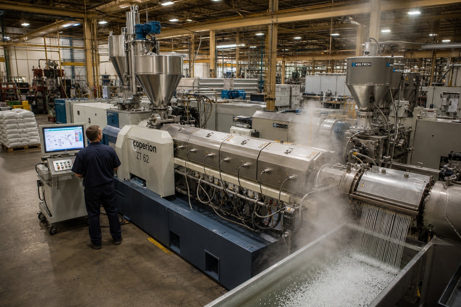
That mastery of feed rate, screw speed, and barrel temperature is not theoretical — it plays out differently in every industry that relies on a co-rotating twin screw extruder. The same modular platform that compounds glass-fiber-reinforced nylon at 300 kg/h can, with a different screw profile and downstream setup, produce pharmaceutical solid dispersions at 5 kg/h or recycle post-consumer polyethylene at over 2,000 kg/h. What changes is not the machine's core architecture but how each industry leverages its zones, elements, and process variables to solve fundamentally different problems.
Compounding and Masterbatch Production
Polymer compounding remains the largest single application for twin screw extruders. The objective is straightforward: blend a base resin with fillers, reinforcements, or modifiers to create a compound with properties the neat polymer cannot deliver on its own.
Filled compounds — glass fiber in polyamide, calcium carbonate in polypropylene, carbon black in polyethylene — demand the full six-zone architecture described earlier. Glass fibers enter through a downstream side stuffer to preserve fiber length, while calcium carbonate can be introduced at the main feed throat or through a secondary side feeder depending on loading level. The kneading blocks in the mixing zone must break apart filler agglomerates without over-shearing the polymer matrix, a balance that shifts with every percentage point of filler content.
Polymer blends and alloys — think PC/ABS, PP/EPDM, or PA/PPO — rely even more heavily on distributive mixing. Here, the challenge is not breaking particles apart but stretching and folding two immiscible melt phases until domain sizes reach the submicron range needed for mechanical compatibility. Toothed mixing elements and narrow forward-staggered kneading blocks often deliver better results than aggressive 90° blocks, which can overheat the melt and coarsen the morphology instead of refining it.
Masterbatch production pushes pigment loading to extremes — sometimes 40% to 70% by weight in a carrier resin. Color concentrates require exceptional distributive mixing to eliminate any visible pigment streaks or agglomerates in the final co extruded or injection-molded part. Additive masterbatches for UV stabilizers, flame retardants, or antioxidants follow a similar logic: the twin screw extruder's ability to deliver both high shear for dispersion and gentle folding for distribution in a single pass makes it the only practical platform for these formulations. In coextrusion applications, for instance, masterbatch quality directly determines the color uniformity of each layer in a multi-layer film or sheet — a defect in the concentrate becomes a defect across every downstream product.
Reactive Extrusion and Pharmaceutical Applications
Reactive extrusion transforms the barrel into a continuous chemical reactor. Grafting maleic anhydride onto polypropylene, crosslinking polyethylene with peroxides, or performing controlled degradation of polypropylene to narrow its molecular weight distribution — all of these reactions happen inside the extruder in residence times measured in seconds rather than the hours a batch reactor would require.
The narrow residence time distribution of the co-rotating intermeshing geometry is critical here. Every polymer chain must experience the same thermal and chemical history for the reaction to proceed uniformly. Liquid injection ports introduce peroxide initiators or reactive monomers at precisely controlled locations, and melt seals created by reverse elements prevent unreacted volatiles from migrating upstream. Devolatilization zones downstream strip out reaction byproducts and unreacted monomer, delivering a clean product in a single continuous pass.
Pharmaceutical hot-melt extrusion (HME) applies the same platform to drug delivery. More than 50% of active pharmaceutical ingredients belong to BCS Class II — poorly water-soluble compounds that limit bioavailability in conventional tablet form. By molecularly dispersing these drugs into a polymeric carrier matrix at elevated temperatures, HME converts crystalline APIs into amorphous solid dispersions with dramatically improved dissolution rates. The co-rotating twin screw extruder is particularly suited to this work because its self-wiping action ensures consistent residence time, its modular screw design allows fine-tuning of shear and thermal exposure, and its continuous operation eliminates solvent use entirely — an important advantage for regulatory compliance and environmental safety. Downstream, the extrudate is shaped through strand dies, film dies, or calendering rolls depending on the target dosage form.
Food processing represents yet another branch of co extrusion technology. Snack extrusion, texturized vegetable protein, and breakfast cereal production all use co-rotating twin screw extruders for their ability to cook, shear, and shape starch-based or protein-based formulations in a single continuous step. The same principles of starve-fed control and modular screw profiling apply — just with very different materials and much lower barrel temperatures.
Polymer Recycling and Sustainable Manufacturing
The fastest-growing application for co-rotating twin screw extruders is one that barely existed two decades ago: plastics recycling. Both mechanical and chemical recycling methods depend heavily on the extruder's ability to process contaminated, inconsistent feedstocks into uniform, reusable pellets.
In mechanical recycling, post-consumer flakes — washed but still carrying residual moisture, paper labels, adhesive residues, and volatile contaminants — enter the feed throat and must be melted, filtered, degassed, and re-pelletized. The devolatilization zone is arguably more important here than in any other application. Vacuum venting strips moisture, odor-causing volatiles, and low-molecular-weight degradation products that would otherwise compromise the recycled resin's mechanical properties and processability. Twin-screw extruders excel at creating a homogeneous melt from diverse feedstocks such as flakes of varying sizes and colors, a capability that single-screw systems struggle to match when incoming material quality fluctuates batch to batch.
Thermo-mechanical recycling combines recycling and compounding in one step — breaking down post-consumer plastics into a melt, adding reinforcements like glass or calcium carbonate, and producing co extruded pellets ready for injection molding or profile extrusion. Using co-rotating twin screws, facilities have achieved throughputs of up to 14,000 pounds per hour in ultra-pure recycled polypropylene production, demonstrating that recycled content can scale to volumes that compete with virgin material supply chains.
Chemical recycling takes a different approach entirely, using the extruder as a continuous reactor to depolymerize plastics back into monomers or chemical feedstocks. Here, the barrel functions as a high-temperature, high-pressure reaction vessel, and the screw profile is designed to maximize residence time and thermal energy input rather than gentle conveying. This method handles mixed plastic streams that mechanical recycling cannot — enabling circularity for materials that would otherwise go to landfill or incineration.
The table below maps each major industry to the specific process type, the key extruder features utilized, and the downstream equipment that completes the production line:
| Industry | Process Type | Key Extruder Features Utilized | Downstream Equipment |
|---|---|---|---|
| Polymer Compounding | Filled compounds, polymer blends and alloys | Side stuffers, intensive kneading zones, devolatilization | Strand pelletizer, underwater pelletizer |
| Masterbatch Production | High-pigment color concentrates, additive masterbatch | Distributive mixing elements (TME/ZME), high L/D ratio | Strand pelletizer, water-ring pelletizer |
| Reactive Extrusion | Grafting, crosslinking, controlled degradation | Liquid injection ports, melt seals, vacuum venting, narrow RTD | Strand die, underwater pelletizer |
| Plastics Recycling | Mechanical recycling, thermo-mechanical recycling, chemical recycling | Multi-stage devolatilization, high torque drive, melt filtration integration | Underwater pelletizer, strand pelletizer, melt filter |
| Pharmaceutical HME | Amorphous solid dispersions, controlled-release formulations | Precise temperature control, modular kneading profiles, self-wiping for narrow RTD | Film die, strand die, calendering rolls, pelletizer |
| Food Processing | Snack extrusion, texturized protein, cereal production | Cooking/shear zones, steam injection, starve-fed control | Cutting knife, sheet die, forming die |
Across every one of these industries, a common thread emerges: the co-rotating twin screw extruder succeeds not because it is optimized for one task but because its modular, zone-based architecture can be reconfigured for almost any continuous processing challenge. That versatility, however, creates a new problem — with so many possible configurations and applications, how do you select the right machine in the first place?
How to Select the Right Co-Rotating Twin Screw Extruder
Selecting a co-rotating twin screw extruder is not a catalog exercise — it is a process-engineering decision with consequences that compound over years of operation. The wrong screw diameter limits throughput permanently. The wrong torque class forces compromises on every formulation. The wrong barrel metallurgy turns a five-year asset into a two-year consumable. Yet most buyer's guides from twin screw extruder manufacturers treat selection as a feature comparison rather than a decision framework tied to your specific materials, volumes, and quality targets.
The checklist below organizes the critical specifications in the order they should be evaluated — each one narrowing the field before the next is considered.
Key Specifications That Drive Extruder Selection
- Screw diameter and L/D ratio — Diameter is the primary sizing parameter because production capacity scales roughly with the square of the screw diameter. A 35 mm machine might deliver 50-150 kg/h, while a 92 mm platform can exceed 2,000 kg/h. L/D ratio then determines how much processing length you have available. Simple compounding tasks — single filler, one mixing zone, no devolatilization — may work at 32:1 to 36:1. Complex operations involving side feeding, multiple mixing stages, reactive zones, and vacuum venting typically require 44:1 to 52:1 or longer. If you anticipate future formulation complexity, specifying a longer barrel upfront is almost always cheaper than retrofitting later.
- Specific torque class — As discussed earlier, specific torque (Nm/cm3) defines how much energy the machine can transfer per revolution. Match it to your most demanding formulation. High-viscosity engineering polymers and heavily filled compounds (above 40% loading) need platforms in the 13-18 Nm/cm3 range. General-purpose polyolefin compounding at moderate filler levels may run comfortably at 9-11 Nm/cm3. Choosing a torque class that only barely handles your current recipe leaves no headroom for future products or process optimization.
- Screw speed range — Maximum screw speed determines the upper limit of shear rate and specific energy input. High-speed machines (up to 1,200 rpm on some modern platforms) suit heat-sensitive materials that benefit from short residence times — the material passes through quickly before thermal degradation can accumulate. Lower maximum speeds (300-600 rpm) are appropriate for shear-sensitive compounds where excessive mechanical energy would damage polymer chains or fiber reinforcements. Evaluate the full speed range, not just the maximum — process flexibility depends on how low the drive can run while maintaining stable torque.
- Downstream integration — The extruder does not operate in isolation. Your end product determines whether you need strand pelletizing, underwater pelletizing, water-ring pelletizing, or direct extrusion to a sheet or profile die. Confirm that the machine's discharge pressure capability, melt temperature range, and die adapter geometry are compatible with your downstream equipment. A mismatch here creates bottlenecks that no screw profile adjustment can fix.
Barrel Metallurgy and Wear Protection Considerations
Barrel and screw material selection is one of the most consequential — and most frequently underestimated — decisions in the entire selection process. The reason is simple: as soon as the screw begins rotation inside the barrel, wear begins. Abrasive fillers like glass fiber and mineral additives accelerate that wear dramatically. Corrosive polymers such as PVC or fluoropolymers attack barrel linings chemically, undermining surfaces that abrasion alone would leave intact.
Three wear mechanisms drive barrel and screw degradation:
- Abrasive wear — Hard filler particles grind against screw flights and barrel walls, progressively widening clearances. This is the dominant wear mode in glass-fiber and mineral-filled compounding. Bimetallic barrel liners with high tungsten carbide content and hardfaced screw flights are the standard countermeasure.
- Adhesive wear — Metal-to-metal contact between screw flight tips and barrel bore creates localized welding and tearing. Proper alignment and compatible alloy pairings between screw hardfacing and barrel lining reduce this risk. Incompatible metals — softer materials paired with harder surfaces — have a greater tendency to gall, leading to premature failure.
- Corrosive wear — Chemical attack from aggressive polymer decomposition products (particularly hydrochloric acid from PVC or hydrofluoric acid from fluoropolymers) degrades barrel surfaces at the molecular level. Nickel-based alloys and corrosion-resistant barrel liners are essential for these applications.
The practical consequence of getting metallurgy wrong is not just shortened component life — it is cascading process degradation. As clearances widen, melting efficiency drops, leakage flow increases, and operators begin compensating with higher screw speeds and adjusted temperatures. Those compensations use more energy and affect part quality, often in small increments that go unnoticed until productivity falls off a cliff. Specifying the right barrel and screw alloys from the start — and replacing them before the "point of diminishing returns" — is far cheaper than running degraded hardware.
Evaluating Replacement Parts and Supplier Partnerships
Here is a reality that equipment brochures rarely mention: barrels and screws are consumable components. Even with optimal metallurgy, a high-throughput compounding line processing abrasive fillers will need barrel replacements on a predictable cycle. The total cost of ownership for any twin-screw extruder manufacturer's equipment depends as much on parts availability and lead times as on the initial purchase price.
When evaluating suppliers, consider these factors beyond the machine itself:
- Replacement parts lead time — Can you source a replacement barrel or screw element set within days, or are you facing weeks of downtime waiting for OEM-only supply? Every day of unplanned shutdown carries a production cost that can dwarf the price of the part itself. Industry data suggests that even modest downtime rates of 10-15% of production hours can erase hundreds of thousands of dollars in annual output.
- OEM vs. specialist barrel suppliers — Relying exclusively on the original machine manufacturer for barrels often means longer lead times and premium pricing. Specialist suppliers that focus on barrel and screw manufacturing can deliver equivalent or superior metallurgy at lower cost. NANHAIYA's Parallel Twin Screw Barrel line, for example, supports compounding, masterbatch, recycling, and pelletizing operations with replacement and custom barrels engineered for stable conveying and high-wear resistance — providing an alternative supply chain that reduces both downtime and per-part cost.
- Used twin screw extruder considerations — Purchasing a used twin screw extruder can offer significant capital savings, but the barrel and screw condition must be inspected carefully. Measure bore diameter at multiple points along the barrel length and compare against original tolerances. If clearances have opened beyond acceptable limits, factor in the cost of replacement barrels and screw elements before committing — the "bargain" machine with worn internals can quickly become more expensive than a new platform once rebuild costs are included.
- Technical support depth — Does the manufacturer or supplier offer screw profile recommendations for your specific materials? Can they provide metallurgical guidance for barrel liner selection? The best twin screw extruder manufacturers back their hardware with application engineering support — not just a parts catalog.
Selecting the right machine is only half the equation. The other half is building a reliable supply chain for the components that wear out — because the extruder that runs the longest between unplanned stops is the one that delivers the lowest cost per kilogram over its lifetime. That supply chain extends beyond the extruder itself into the upstream and downstream systems that surround it, forming the complete extrusion line that ultimately determines plant-level performance.
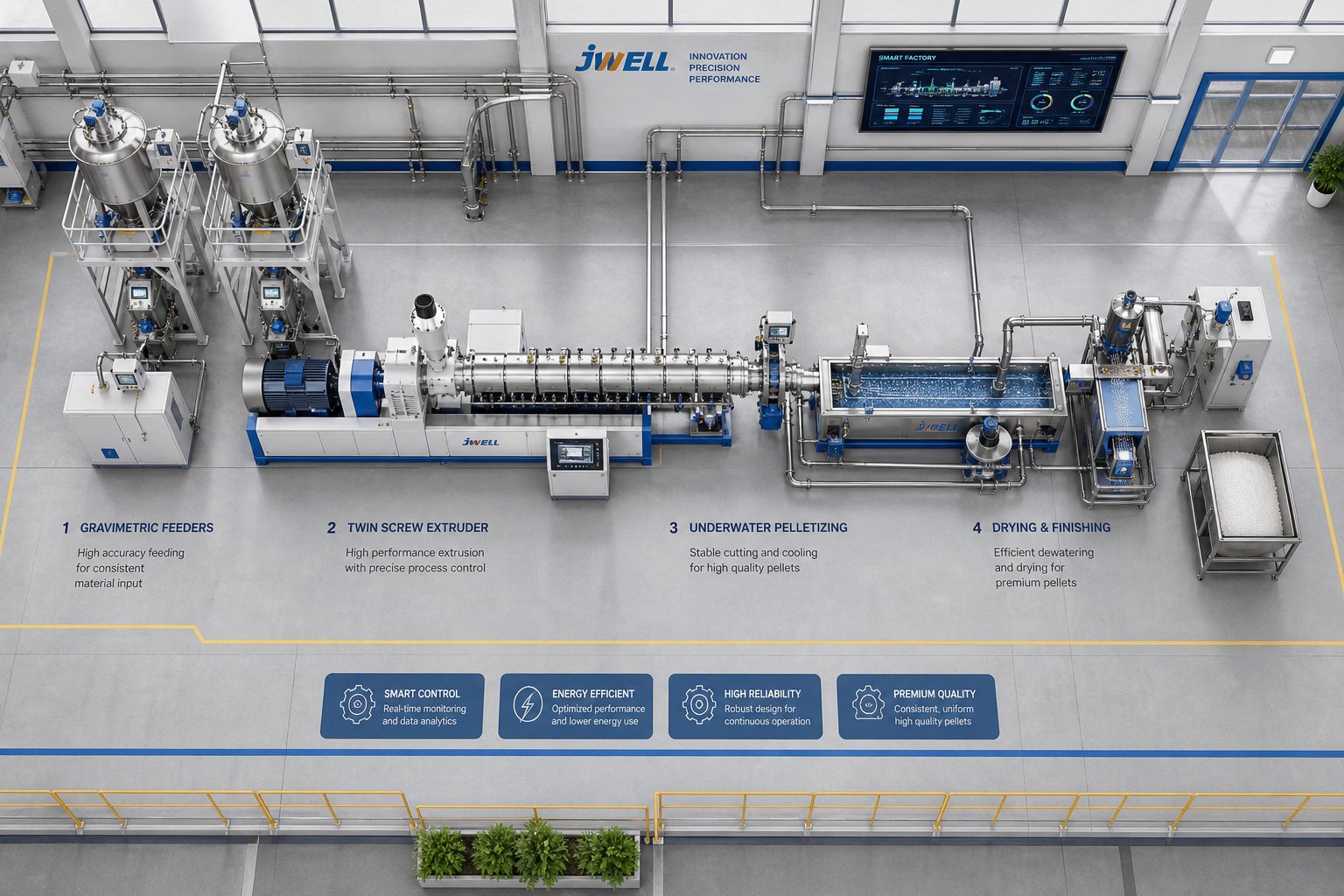
Building a Complete Extrusion Line Around the Twin Screw
A co-rotating twin screw extruder sitting alone on a factory floor produces nothing. It needs material fed into it at precise rates, instruments monitoring what happens inside, and equipment downstream to turn the exiting melt into a usable product. Treating the extruder as an isolated machine — rather than the central hub of an integrated processing line — is one of the most common mistakes engineers make when specifying or scaling up production. The systems surrounding the twin screw often determine whether the line runs at 95% uptime or struggles to hold 70%.
Upstream Feeding Systems and Material Handling
Everything that enters the barrel must arrive at a controlled rate, in the right sequence, and at the right location along the process section. Since a co-rotating twin screw extruder is a starve-fed device, the feeding system does not merely supply material — it sets the production rate and maintains formulation accuracy. A twin-screw system may use up to eight or more feed streams, each requiring its own metering device and control loop.
The major upstream equipment categories include:
- Gravimetric (loss-in-weight) feeders — The gold standard for starve-fed operation. A hopper sits on a load cell, and the control system adjusts auger speed to maintain a constant mass flow rate based on the rate of weight change. For direct extrusion applications where dimensional tolerances are tight, volumetric feeders are generally not acceptable due to inherent feedrate fluctuations that propagate into pressure instability at the die. Gravimetric feeders eliminate that variability.
- Volumetric feeders — Simpler and less expensive, these deliver material by volume rather than weight. They work adequately for premixed formulations or processes where modest throughput variation is tolerable — typically pelletizing operations where a plus or minus 20% dimensional tolerance on the pellet is acceptable.
- Side stuffers — Co-rotating, intermeshing twin screw augers mounted on a side-feed barrel section. They push fillers, fibers, or heat-sensitive additives directly into the melt stream downstream of the primary melting zone. Glass fiber, calcium carbonate, talc, and carbon black are commonly introduced this way to avoid unnecessary exposure to the high-shear plastication region.
- Liquid injection systems — Piston or gear pumps that meter oils, coupling agents, plasticizers, or reactive monomers into the barrel at specific locations. The injection point must align with a partially filled screw section so the liquid absorbs into the melt rather than pooling or flashing off as vapor.
- Crammer feeders — Specialized devices for highly filled or low-bulk-density materials that resist flowing by gravity into a standard feed throat. They mechanically force material into the screw channels.
Imagine running a 60% calcium carbonate filled polypropylene compound. The base resin enters through the main feed throat via a gravimetric feeder. The mineral filler is delivered by a second gravimetric feeder into a side stuffer mounted six barrel sections downstream. A liquid coupling agent is injected through a piston pump into the barrel section immediately before the mixing zone. Each of these three feed streams must maintain its own mass flow accuracy — because any drift in one stream shifts the entire formulation ratio. That coordination is why the feeding system, not the extruder, is often the most complex subsystem on the line.
Downstream Pelletizing and Forming Options
What happens after the melt exits the die determines the final product form — and the choice of downstream extrusion equipment must match both the material's properties and the intended application. The four primary downstream paths are:
- Strand pelletizing — The melt exits through a multi-hole strand die, forming continuous strands that pass through a water bath for cooling, an air knife for drying, and finally a strand pelletizer that cuts them into cylindrical pellets. This extruder pelletizer configuration is mechanically simple, easy to maintain, and cost-effective for small to medium production rates. It works best with materials that form stable, consistent strands — most polyolefins, engineering polymers, and moderately filled compounds. As one industry comparison notes, strand pelletizing provides a practical balance between pellet quality and system cost, particularly for recycling operations.
- Underwater pelletizing — The melt is cut directly at the die face by rotating knives submerged in a water stream. Pellets solidify almost instantly into uniform, spherical shapes with minimal fines. This method excels at high throughput rates and handles low-viscosity or sticky melts that would break during strand cooling. The trade-off is significantly higher system complexity — closed-loop water circulation, centrifugal dryers, and precise die-face alignment all add cost and maintenance demands.
- Water-ring pelletizing — A middle ground between strand and underwater systems. The melt is cut at the die face, but instead of being fully submerged, the pellets are thrown outward into a ring of circulating water. It is simpler than underwater pelletizing while still producing rounder pellets than strand cutting. This co extruder downstream option is popular for masterbatch and recycling lines where pellet geometry matters but capital budgets are constrained.
- Direct extrusion to sheet, film, or profile dies — In some applications, pelletizing is eliminated entirely. The twin screw extruder feeds a melt stream directly into a sheet die, flat film die, or a coextrusion profile die, bypassing the intermediate pelletizing and remelting steps. Direct extrusion was initially mandated by the need to produce formulations adversely affected by the second heat and shear history inherent in remelting pellets on a single-screw line. It has since proven to deliver substantial cost savings for products like filled sheeting, foamed profiles, and wood-fiber composites. For a co extrusion machine configuration producing multi-layer products, a gear pump or single-screw pump front-end attachment is often specified between the twin screw extruder and the die to dampen pressure fluctuations — a gear pump can reduce pressure variation by roughly a factor of ten.
Process Monitoring and Real-Time Quality Control
Between the feeders and the pelletizer, process monitoring instruments close the feedback loop that keeps the line running within specification. The core measurements include:
- Melt temperature sensors — Thermocouples or infrared probes inserted at the die adapter or at intermediate barrel positions. Melt temperature reflects the combined effect of barrel heating and viscous dissipation from screw work — it is the single best indicator of whether the process is delivering consistent thermal history.
- Die pressure transducers — Pressure at the die inlet must remain stable for uniform extrudate dimensions. Fluctuations signal changes in feed rate, melt viscosity, or screen pack blockage upstream.
- Motor torque monitoring — Tracking the percentage of available torque consumed during operation reveals formulation shifts, wear-related clearance changes, or feeding irregularities. Specific energy — calculated from motor power, torque percentage, screw speed, and feed rate — serves as a reliable indicator of any change to the process, whether hardware or material related.
- Near-infrared (NIR) and inline viscometry — Advanced probes integrated into the barrel or die adapter allow real-time compositional and rheological analysis. These tools support continuous quality verification without pulling offline samples, aligning with modern process analytical technology (PAT) frameworks.
Why Continuous Processing Replaces Batch Mixing
All of this upstream feeding, inline monitoring, and downstream forming exists because the twin screw extruder operates continuously — and that continuous paradigm offers fundamental advantages over batch mixing that no amount of batch-process optimization can close.
In a batch mixer, materials are loaded, mixed for a set cycle time, and discharged in discrete lots. Every lot carries its own variability — slightly different peak temperatures, different shear histories, different mixing durations at the beginning versus the end of the batch. The co-rotating twin screw extruder, by contrast, processes material in a first-in, first-out sequence with residence times ranging from as short as 5 seconds to as long as 6 to 10 minutes, depending on screw design and process conditions. Every kilogram of material experiences the same thermal and mechanical environment, producing consistency that batch systems cannot replicate.
The practical benefits compound from there:
- Throughput scalability — Increasing output on a batch mixer means buying more mixers or running longer shifts. On a twin screw line, output scales by adjusting feeder rates and screw speed within the machine's torque envelope — or by moving to a larger screw diameter platform while keeping the same screw profile logic.
- Energy efficiency — The short mass transfer distances inside a twin screw extruder mean less total energy is needed per kilogram of compound compared to a large-mass batch mixer, where materials far from the rotor blades receive inconsistent shear.
- Reduced labor and footprint — A continuous line with automated feeders and inline monitoring can run with fewer operators than a batch operation producing the same tonnage. The equipment footprint is typically smaller, too — a 40:1 L/D twin screw line occupies a fraction of the floor space needed for equivalent batch capacity.
- Faster formulation development — Adjusting formulations inline — changing a feeder ratio, shifting a barrel temperature, swapping a kneading block — delivers immediate feedback. Batch systems require completing and testing an entire lot before the effect of any change becomes visible.
The transition from batch to continuous processing via twin screw extrusion follows the same trajectory in pharmaceuticals, food, and plastics: once the quality and consistency advantages are demonstrated, the economic case becomes overwhelming.
This integrated-line perspective — feeders setting formulation accuracy, the extruder delivering mixing and devolatilization, downstream equipment forming the final product, and instruments verifying quality throughout — is what separates a productive extrusion operation from one that merely owns an extruder. Yet even the best-configured line degrades over time as barrels wear, screw elements erode, and clearances open up. Sustaining that performance over years of production requires a clear strategy for maintenance, component replacement, and forward-looking technology adoption.
Key Takeaways and Next Steps for Processing Engineers
Every concept explored in this article — from the kinematic sweep of self-wiping flights to the three-axis control logic of starve-fed operation — traces back to three foundational design principles. These principles do not operate in isolation. They interlock, and that interlocking is precisely what makes the co-rotating twin screw extruder the dominant continuous processing platform across plastics, pharmaceuticals, food, and recycling.
Three Design Principles That Drive Extruder Performance
Strip away the complexity, and you'll find that every process outcome on this machine traces back to three pillars:
- Self-wiping intermeshing geometry — Same-direction rotation forces each screw flight to sweep the channel of its neighbor, eliminating dead zones, narrowing residence time distribution, and preventing material degradation. This single kinematic feature is what separates the co-rotating platform from every competing architecture.
- Modular screw and barrel construction — Segmented elements on splined shafts, combined with interchangeable barrel sections, transform a fixed piece of hardware into a reconfigurable processing tool. The same machine handles gentle polymer blending, aggressive mineral-filler dispersion, and reactive grafting chemistry — all by rearranging elements along the shaft and repositioning vent, feed, and injection ports.
- Starve-fed process control — Gravimetric feeding decouples throughput from screw speed, giving operators independent control over production rate, mixing intensity, and thermal exposure. This three-variable control space is what elevates the extruder from a material-moving device to a precision engineering platform.
These three principles reinforce each other. Self-wiping geometry makes modular element swaps practical — there is no residual material buildup to contaminate the next formulation. Modular construction makes starve-fed control meaningful — you can actually tailor each zone's fill level and shear profile because the elements respond differently to changes in feed rate and screw speed. Remove any one pillar, and the platform loses much of its processing flexibility.
Five key principles worth carrying forward from this article:
- Think in six processing zones, not three — solids conveying, melting, melt mixing, melt conveying, devolatilization, and die pressurization each demand distinct element configurations and operating strategies.
- Evaluate extruders by specific torque (Nm/cm3), not just motor horsepower — this metric determines whether the machine can handle your most demanding formulations with headroom for optimization.
- Use throughput as a quality lever — research consistently shows that increasing feed rate shortens residence time, reduces oxygen exposure, and lowers specific energy input per kilogram, protecting material properties across polymer types.
- Specify barrel metallurgy to match your fillers and polymers — abrasive wear from glass fiber, adhesive wear from metal-to-metal contact, and corrosive wear from aggressive decomposition products each require different alloy strategies. Getting this wrong accelerates every other form of process degradation.
- Design the complete line, not just the extruder — feeders set formulation accuracy, downstream equipment determines product form, and inline monitoring closes the quality loop. A world-class extruder surrounded by poorly matched peripherals underperforms a modest machine in a well-integrated line.
Keeping Your Extruder Running with Quality Barrel and Screw Components
Here is the maintenance reality that every processing engineer eventually confronts: the twin screw barrel and screw elements are consumable components. No metallurgy eliminates wear entirely — it only controls the rate. In high-throughput compounding lines processing abrasive fillers, barrel bore diameters can open beyond tolerance within months of continuous operation. Industry maintenance data indicates that 60% of twin screw extruder failures trace back to improper maintenance of screw and barrel components, and proactive replacement programs can reduce operating costs by 20-30% compared to reactive approaches that wait for failure.
When clearances widen, the consequences cascade silently. Melting efficiency drops. Leakage flow increases. Operators compensate with higher screw speeds and adjusted temperatures — burning more energy and shifting product properties without realizing the root cause is hardware degradation, not a process variable. By the time output quality visibly suffers, the barrel may already be far past its optimal replacement window.
Sourcing quality replacement barrels and screw elements quickly — without being locked into a single OEM supply chain with extended lead times — is essential for sustained performance. NANHAIYA's Parallel Twin Screw Barrel product line addresses this directly, providing replacement and custom-engineered barrels for compounding, masterbatch, recycling, and pelletizing operations. Their focus on stable conveying performance and high-wear resistance makes them a practical alternative for plants that cannot afford weeks of downtime waiting for OEM-only parts. Building a diversified supply chain for these consumable components is not a cost-cutting tactic — it is a risk management strategy that protects uptime and cost-per-kilogram economics over the full life of the machine.
Looking ahead, the twin screw extruders market — valued at USD 2.91 billion in 2024 and projected to grow at a 5.06% CAGR through 2034 — reflects where this technology is heading. Higher specific torque densities are pushing processing envelopes further, enabling co extrusions with increasingly complex formulations and filler loadings that were impractical a decade ago. Tighter real-time process controls, including inline NIR spectroscopy and AI-driven adaptive screw speed optimization, are closing the gap between laboratory precision and production-floor throughput. Bio-based polymers, chemical recycling, and circular economy applications are expanding the machine's role from a compounding tool into a sustainability platform — processing feedstocks that did not exist when the self-wiping geometry was first engineered over half a century ago.
The co-rotating twin screw extruder is not just keeping pace with these shifts. Its modular, zone-based architecture is the reason these shifts are possible in the first place.
Frequently Asked Questions About Co-Rotating Twin Screw Extruders
1. What is the difference between co-rotating and counter-rotating twin screw extruders?
Co-rotating twin screw extruders have both screws turning in the same direction, producing a true self-wiping action where one screw flight sweeps material from the other's channel. This eliminates dead zones and delivers a narrow residence time distribution ideal for compounding and reactive processing. Counter-rotating extruders draw material into a calendering gap between the screws, generating higher pressure but with weaker self-cleaning. Counter-rotating designs are best suited to shear-sensitive materials like rigid PVC, while co-rotating machines dominate applications requiring intensive, tunable mixing and process flexibility.
2. Why are co-rotating twin screw extruders starve-fed instead of flood-fed?
Starve feeding uses gravimetric feeders to meter material into the barrel at a controlled mass flow rate independent of screw speed. This decouples throughput from mixing intensity, giving operators three independent control axes: feed rate for production volume, screw speed for shear and energy input, and barrel temperature for thermal management. Flood-fed single-screw extruders tie throughput directly to screw speed, limiting process optimization. Starve feeding is what makes the co-rotating twin screw extruder a true process-engineering platform capable of fine-tuning compound quality for each formulation.
3. How many processing zones does a co-rotating twin screw extruder have?
A co-rotating twin screw extruder is most accurately described as having six distinct processing zones rather than the simplified three-stage model found in most textbooks. These zones are: (1) solids conveying, (2) melting and plastication, (3) melt mixing for dispersive and distributive action, (4) melt conveying and pumping, (5) devolatilization for removing moisture and volatiles, and (6) die pressurization for stable output. Each zone operates at different fill levels, shear intensities, and residence times, and engineers configure screw elements and barrel segments zone by zone to match specific material and formulation requirements.
4. What is specific torque and why is it important for twin screw extruder selection?
Specific torque measures the torque available per cubic centimeter of free screw volume (Nm/cm3) and indicates how much energy the machine can transfer into the material per revolution. It is the most critical specification for matching an extruder to demanding formulations. High-viscosity engineering polymers and compounds with filler loadings above 40% require platforms rated at 13-18 Nm/cm3 to avoid motor overload. Choosing adequate specific torque provides headroom for process optimization, allowing lower barrel temperatures to protect heat-sensitive additives or higher throughputs without tripping the drive. Always check this metric before evaluating other machine features.
5. How often do twin screw extruder barrels and screws need replacement?
Replacement frequency depends on the materials processed, filler abrasiveness, and barrel metallurgy. High-throughput lines running glass-fiber or mineral-filled compounds can see barrel bore diameters open beyond tolerance within months of continuous operation. Industry data shows that 60% of twin screw extruder failures trace back to improper barrel and screw maintenance. Proactive replacement programs reduce operating costs by 20-30% compared to reactive approaches. Specialist suppliers like NANHAIYA offer replacement and custom parallel twin screw barrels engineered for high-wear resistance, providing faster lead times and competitive pricing compared to OEM-only supply chains.
Written by
Nanhaiya Technical Team
Zhoushan Nanhaiya Plastic Machinery Co., Ltd.
The Nanhaiya technical team supports screw and barrel manufacturing projects through application review, technical communication, custom manufacturing coordination, and production and quality control.
Discuss Your Application
Related Articles
More insights on screw barrel technology and plastics processing.

What Nobody Tells You About Screw Barrel For Plastic Machine Design
Oct 10, 2026
Learn how screw barrel for plastic machine design affects melt quality, throughput, and wear life. Covers geometry, resin matching, troubleshooting, and sourcing.
Read Article
Single Screw Extruder for Sheet: Stop Guessing, Start Specifying
Oct 9, 2026
Learn how to specify a single screw extruder for sheet production. Covers screw geometry, resin-specific processing, troubleshooting, and maintenance best practices.
Read Article
PE Pipe Extruder Machine: What Datasheets Won't Tell You
Oct 9, 2026
Learn how a PE pipe extruder machine works, key specs explained, material grade selection, maintenance tips, and buyer guidance beyond the datasheet.
Read ArticleLooking for something else?
Search by material, symptom or product and jump straight to the relevant page.
These are navigation suggestions based on keyword matching — not a quotation, not a delivery commitment, and not a substitute for engineering review. Final specification is confirmed by our engineers against your drawings and processed material.
Need help with screw barrel selection?
Share your machine model, processed material and application. Our team can help with pricing and technical support.