

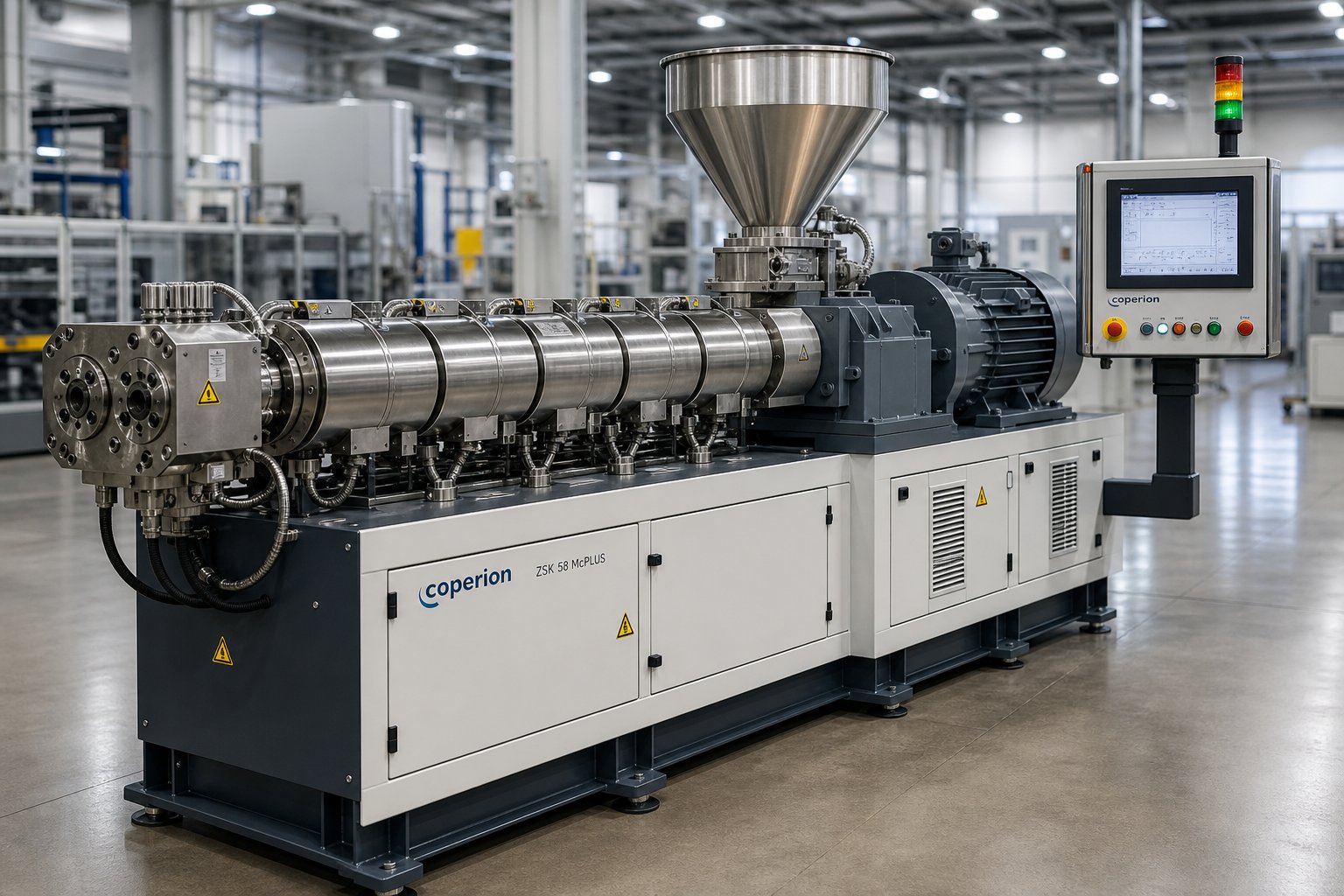
What Is a Co-Rotating Parallel Twin Screw Extruder
Imagine two screws sitting side by side inside a heated barrel, their flights interlocking like meshed gears, both spinning in the exact same direction. That is the core idea behind a co-rotating parallel twin screw extruder — a machine engineered to continuously mix, melt, and convey materials with a level of control that single-screw systems simply cannot match. Unlike counter-rotating designs, where the screws turn in opposite directions and create a calendering nip, the co-rotating configuration forces material along a figure-eight pathway from one screw channel to the other, producing intense yet highly uniform mixing.
Defining the Co-Rotating Parallel Configuration
Three geometric traits set this twin screw extruder apart from every other variant. First, the screw axes run perfectly parallel, maintaining a constant center-line distance and uniform diameter from feed end to discharge. Second, the flight profiles are fully intermeshing — the crest of one screw reaches into the channel of its partner, leaving minimal dead space. Third, both screws rotate in the same direction, which is the detail that unlocks self-wiping behavior: each flight tip continuously sweeps the root of the adjacent screw, preventing material from stagnating or degrading on hot metal surfaces. Conical twin screw extruders, by contrast, taper from a large feed diameter to a smaller discharge end and almost always run in counter-rotation — a geometry optimized for direct extrusion of rigid PVC rather than versatile compounding.
Why This Extruder Type Dominates Modern Processing
You will find this parallel twin screw extruder at the heart of nearly every polymer compounding line, masterbatch facility, and reactive extrusion operation worldwide, and the reasons are practical rather than theoretical.
A co-rotating parallel twin-screw extruder delivers superior dispersive and distributive mixing, a narrow residence-time distribution, and fully modular screw and barrel construction — making it the default platform for compounding, devolatilization, reactive processing, and filled-polymer systems.
Because the screw elements can be rearranged in countless sequences, engineers tailor mixing intensity, shear input, and throughput to each specific formulation without replacing the entire shaft. Scalable throughput rounds out the advantage: the same element-design philosophy applies whether you are running a 16 mm laboratory co rotating twin screw extruder or a 135 mm production machine. That scalability, however, depends on understanding exactly how the self-wiping mechanism and figure-eight flow generate such effective mixing — a topic that hinges on the geometry happening inside the barrel at every screw rotation.
How the Self-Wiping Mechanism and Figure-Eight Flow Work
Every advantage of a co-rotating parallel twin screw extruder — consistent melt quality, minimal degradation, efficient blending — traces back to two geometric phenomena happening inside the barrel on every revolution. Understanding them turns screw extrusion from a black-box operation into a process you can predict and control.
The Self-Wiping Mechanism Explained
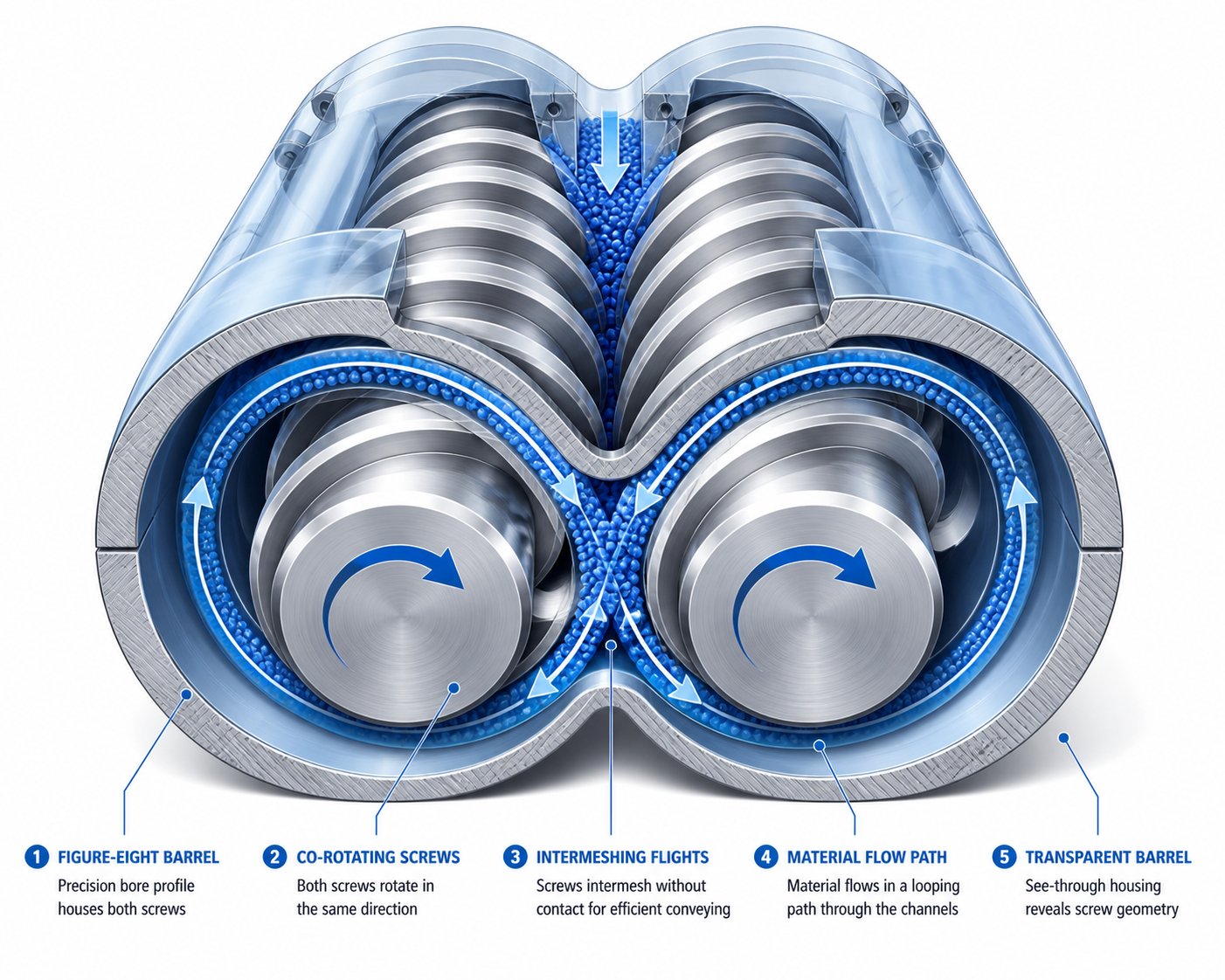
Picture the crest of one screw flight sliding along the root of its partner. Because both twin screws rotate in the same direction, the flight tip of screw A follows the channel of screw B in a continuous sweeping motion. That tip physically scrapes polymer off the metal surface before the material can sit long enough to overheat or degrade.
Why does co-rotation make this possible? When two intermeshing screws spin the same way, the relative motion at the overlap zone pulls material through the nip rather than trapping it. The flight of one screw traces a path that matches the opposing channel geometry almost exactly, leaving only a thin, rapidly renewed film of melt in contact with the barrel wall and screw root. Stagnant pockets — the primary source of black specks, gels, and thermal degradation in polymer processing — are virtually eliminated.
This self-cleaning behavior delivers a practical payoff you will notice immediately: faster color and material changeovers, fewer purge cycles, and a much lower risk of contamination when switching between product runs. In reactive extrusion, where residence-time distribution must stay narrow to ensure uniform reaction completion, the elimination of dead zones is not just convenient — it is essential.
Figure-Eight Flow Pattern and Material Transfer
Sounds complex? The flow path is actually intuitive once you visualize it. Material entering a twin screw channel rides the helical flight forward, just like it would in a single-screw machine. The difference arrives at the intermesh zone — the region where the two screws overlap. Here, the polymer is forced off screw A and onto screw B. It travels forward along screw B's channel until it reaches the next intermesh point, where it transfers back to screw A. Viewed from the discharge end, this looping exchange traces a figure-eight — or infinity symbol — pattern through the barrel cross-section.
Each transfer event reorients the melt stream, splitting and recombining it without relying on brute-force shear. Imagine folding dough repeatedly: every fold doubles the number of layers without tearing the material apart. The figure-eight flow achieves something similar at the molecular level, creating distributive mixing — a thorough spatial rearrangement of every component in the blend. Additives, pigments, or fillers that entered the barrel in a concentrated pocket get spread uniformly throughout the melt over just a few screw diameters of travel.
Critically, this transfer-driven mixing is gentler than what a high-shear kneading block imposes. It adds homogeneity without excessive energy input, which protects shear-sensitive polymers and preserves fiber length in reinforced compounds.
Why Geometry Drives Processing Outcomes
The self-wiping action and figure-eight transfer are not separate features — they work together. Self-wiping keeps every surface fresh, preventing localized overheating, while the constant screw-to-screw transfer ensures no slug of material races through the barrel untouched or lingers far beyond the average residence time. The result is a narrow residence-time distribution paired with a uniform melt temperature across the entire cross-section.
Here is how these geometric characteristics translate directly into processing performance:
- Continuous self-wiping — eliminates dead zones, reduces thermal degradation, and cuts changeover time between product runs.
- Figure-eight material transfer — delivers high distributive mixing efficiency at moderate shear, protecting heat-sensitive formulations and fiber integrity.
- Frequent melt-stream reorientation — promotes uniform additive and filler distribution without requiring excessive barrel length or screw speed.
- Narrow residence-time distribution — ensures every particle of material receives a similar thermal and mechanical history, critical for reactive screw extrusion and color-sensitive compounds.
- Uniform melt temperature — minimizes hot spots and cold pockets, improving die flow consistency and final-product dimensional stability.
These outcomes are not adjustable settings on a control panel — they are baked into the geometry of co-rotating, fully intermeshing twin screws. Every other tunable parameter, from screw element sequence to barrel temperature profile, builds on this geometric foundation. And it is precisely the modular nature of those screw elements that gives engineers the freedom to push these inherent advantages toward very specific processing goals.
Modular Screw Elements and Configuration Design Principles
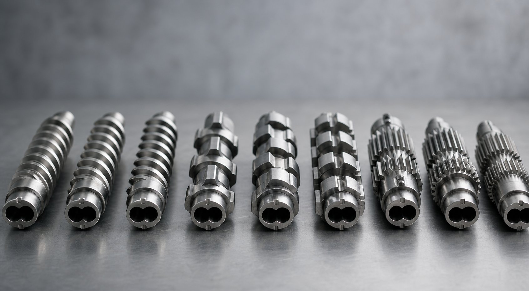
The geometry of co-rotating intermeshing screws creates the mixing and self-wiping foundation, but the real engineering power comes from what sits on the shaft. A screw extruder built with modular elements lets you swap, reorder, and fine-tune individual sections without replacing the entire screw — turning a single machine into a flexible processing platform. Each element type performs a distinct job, and the sequence in which you arrange them determines whether your extruder twin screw setup delivers gentle blending or aggressive dispersion, thorough devolatilization or rapid melting.
Think of screw elements like words in a sentence: each one carries meaning, but the order decides the message. Configuring a screw profile is, as NC State Extension describes it, "a blend of art and science" — because every material behaves differently under heat and shear, and no single arrangement works for all formulations. That said, the element categories themselves follow clear, logical rules.
Conveying Elements and Their Pitch Variations
Conveying elements are the workhorses of material transport. They look like classical helical screw flights, and their primary job is to move material forward through the barrel with minimal energy input. What makes them versatile is pitch — the axial distance covered per full flight revolution.
A large-pitch conveying element sweeps a bigger volume per rotation, making it ideal for the feed zone where loose pellets or powder need to be grabbed quickly and pushed downstream. You will typically see pitches ranging from 1.5 to 2 times the screw diameter in this section. As the material moves toward the melting zone, engineers transition to tighter-pitch elements. A shorter pitch reduces free volume in the channel, compresses the material, and starts building pressure — exactly what you want before the polymer hits the first kneading block.
Reverse-conveying elements — sometimes called left-hand or re-conveying elements — flip the helix direction so the flight pumps material backward. Why would you deliberately push material upstream? Because that backward pressure creates a melt seal. Imagine a dam across a river: the material backs up, fills the screw channels completely, and forms a pressurized plug. This plug is essential upstream of vacuum venting ports, where you need a gas-tight seal to prevent atmospheric air from being sucked into the barrel. Reverse elements also increase local residence time and fill level, intensifying mixing in the zone just before them.
Kneading Blocks and Mixing Elements
When material needs to be melted, dispersed, or blended — not just moved — kneading blocks take over. A kneading block consists of a series of lobe-shaped discs stacked along the shaft, each disc offset from the previous one by a fixed stagger angle. Two variables control how aggressively a kneading block works: disc width and stagger angle.
Disc width determines shear intensity. Narrow discs essentially slice through the polymer, allowing material to flow easily around each disc to the next. The result is distributive mixing — a gentle rearrangement that spreads additives evenly without excessive energy input. Wide discs, by contrast, act more like ploughs. They force a larger fraction of polymer through the high-shear gap between the disc tip and the barrel wall, breaking apart agglomerates and delivering dispersive mixing. As Granuwel's engineering guide explains, a wide-disc element will impart more energy and raise melt temperature noticeably higher than a narrow-disc element of the same length.
Stagger angle controls forward pumping and energy input simultaneously. Here is the practical breakdown:
- 30° stagger — strong forward conveying, minimal mixing intensity. Useful as a transition element pulling material into the melting zone.
- 45° stagger — moderate forward conveying with increased mixing. A balanced choice for many melting applications.
- 60° stagger — weaker forward conveying, significantly stronger mixing and energy input. Common in the core of a melting section.
- 90° stagger (neutral) — no net forward or backward pumping. Polymer is mixed intensely and held in place, creating a restriction that acts as a "melt dam" to ensure complete melting before material moves on.
Reverse kneading blocks — where the disc offset follows a left-hand pattern — push material upstream, creating even more restriction than a 90° neutral block. These are the most aggressive option and are reserved for situations demanding maximum shear, such as melting high-viscosity crystalline polymers.
Beyond standard kneading blocks, toothed mixing elements (sometimes called gear or turbine mixers) provide an alternative path. These elements feature rows of interlocking teeth rather than continuous lobes. They generate excellent distributive mixing at very low shear, making them valuable for homogenizing heat-sensitive formulations or blending low-viscosity additives into a melt without driving up temperature.
| Element Type | Primary Function | Shear Level | Typical Zone Placement |
|---|---|---|---|
| Large-pitch conveying | High-volume material transport | Low | Feed zone, downstream of side feeders |
| Tight-pitch conveying | Compression and pressure buildup | Low to moderate | Pre-melting transition, metering zone |
| Reverse conveying | Melt seal, back-pressure generation | Moderate | Upstream of vacuum vents, end of mixing zones |
| Narrow-disc kneading block | Distributive mixing | Moderate | Blending zones, post-melt mixing |
| Wide-disc kneading block | Dispersive mixing, agglomerate breakup | High | Melting zone, filler dispersion zone |
| 90° neutral kneading block | Melt restriction and intensive mixing | High | End of melting section |
| Reverse kneading block | Maximum restriction and shear | Very high | End of melting section for high-viscosity polymers |
| Toothed mixing element | Low-shear distributive homogenization | Low | Final mixing zone, heat-sensitive blending |
Screw Configuration Design Principles
Knowing what each element does is only half the challenge. The real skill lies in sequencing them to match a specific process. Consider a typical polymer compounding configuration on a co-rotating parallel twin screw extruder — the logic flows from upstream to downstream in a deliberate progression.
The feed zone starts with deep-flight, large-pitch conveying elements to grab incoming pellets or powder efficiently. As material advances, the pitch gradually tightens, compacting the solid bed and preparing it for melting. The melting section then introduces kneading blocks in escalating intensity — perhaps a 30° block to transition smoothly from conveying, followed by one or two 60° blocks to apply serious mechanical energy, and finishing with 90° neutral blocks that act as a melt dam ensuring no unmelted particles slip through.
Immediately downstream of that melt dam, you might place a reverse conveying element to create a gas-tight seal, followed by an open-flight conveying section beneath a vacuum vent port. With the barrel partially filled and the melt seal preventing upstream air intrusion, trapped moisture and volatiles escape efficiently through the vent. After devolatilization, additional mixing elements — narrow kneading blocks or toothed mixers — homogenize any remaining concentration gradients. The configuration closes with metering-zone conveying elements that build stable pressure for consistent die output.
This is just one arrangement. An engineer compounding glass-fiber-reinforced material would shift the aggressive kneading blocks further upstream and use gentle conveying elements near a downstream side-feeder port to protect fiber length. A reactive extrusion setup might call for multiple kneading-and-venting sequences spaced along a longer barrel. The beauty of modular screw extruders is that reconfiguration means sliding elements off and on the splined shaft — not machining a new screw from scratch.
That configurability, however, introduces a question that every screw profile must answer: how much barrel length is available for all these zones? The answer depends on the L/D ratio — a parameter that, together with barrel zone temperature control, shapes every processing decision from feed throat to die face.
L/D Ratio Selection and Barrel Temperature Strategies
Every screw element sequence you design has to fit within a fixed length of barrel. Pack too many functional zones into too short a machine and you compromise mixing quality. Stretch the barrel unnecessarily and you pile on thermal history your polymer never asked for. The parameter that governs this trade-off is the L/D ratio — screw length divided by screw diameter — and it works hand in hand with barrel zone temperature control to define what your twin screw extrusion process can realistically achieve.
How L/D Ratio Shapes Processing Capability
Think of the L/D ratio as a budget of processing real estate. Every functional zone — feeding, melting, mixing, venting, metering — needs a certain number of barrel diameters to do its job properly. A higher ratio gives you more zones or more room within each zone; a lower ratio forces tighter compromises.
General guidelines have emerged across the industry. Shorter L/D configurations, roughly 32:1 to 36:1, handle straightforward compounding tasks where the material melts easily, requires a single mixing stage, and does not need aggressive devolatilization. Color masterbatch production and simple additive incorporation often fall into this range. As Wanplas notes, medium L/D ratios of 32:1 to 36:1 remain the most commonly used in twin screw extrusion, offering a practical balance between mixing intensity and residence time for the majority of polymer processing applications.
Longer L/D configurations — 40:1 to 52:1 and beyond — become necessary when the process demands more. Reactive extrusion requiring extended residence time for chemical conversion, multi-stage devolatilization with two or more vacuum vents, or formulations needing several downstream injection points for liquid additives and side-fed fillers all consume extra barrel length. A 40:1 machine, for instance, can accommodate a full melting section, a first vent, a downstream side-feed port for glass fiber, a second kneading zone, and a final vacuum vent — a sequence that simply would not fit on a 32:1 barrel.
Here is the critical nuance most guides overlook: longer is not automatically better. Every additional barrel section the melt passes through adds cumulative shear history and thermal load. For heat-sensitive polymers like PVC or certain bioplastics, that extra residence time can trigger degradation, discoloration, or molecular weight loss. An industry perspective from Technovel reinforces this point — even with the same material, small differences in operating conditions can lead to large changes in flow behavior and final product quality. Choosing the shortest L/D that satisfies all process requirements is almost always the smarter engineering decision.
Barrel Zone Temperature Control Strategies
Selecting the right L/D ratio gives you the physical space, but what happens inside that space depends heavily on how you manage heat. In modern twin-screw extruders, the barrel is built from modular sections — typically four to twelve segments depending on the machine length — and each segment has independent heating and cooling capability. Electric heaters or oil-circulation jackets raise the temperature, while liquid-cooled channels or forced-air systems pull heat away.
What makes barrel temperature control tricky is that the barrel set point and the actual melt temperature often diverge, sometimes dramatically. The reason? Viscous dissipation. When aggressive kneading blocks shear a high-viscosity polymer, they convert mechanical energy into heat directly within the melt. In these zones the polymer can run 20 to 40 degrees Celsius above the barrel set temperature, and active cooling becomes essential just to prevent overshoot. Meanwhile, in gentle conveying sections downstream of a vent port, the partially filled barrel loses heat through exposed surfaces, and the heaters must work to maintain adequate melt temperature.
Screw element configuration and barrel zone temperatures must be optimized together as a coupled system — adjusting one without considering the other leads to unpredictable melt temperatures and inconsistent product quality.
This coupling shows up clearly when you compare processing strategies for different polymer families. Amorphous polymers like ABS or polycarbonate soften gradually over a broad temperature window. Their barrel profiles tend to ramp up gently from feed to discharge, and the kneading zone does not need a sharp thermal spike to initiate melting. Cooling in the kneading zone is moderate — enough to offset viscous dissipation without risking a stall in the melting process.
Semi-crystalline polymers — polyamides, polyethylene, PBT — behave differently. They resist softening until they hit a relatively narrow melting point, then flow readily. The barrel zone containing the primary kneading blocks typically runs at or slightly above the crystalline melt temperature to ensure rapid phase transition, while downstream zones may be cooled aggressively to bring the melt to an ideal processing temperature. Getting this profile wrong can leave unmelted crystals in the final product or push the melt into a degradation window.
In practice, engineers build a temperature map that mirrors the twin screw extrusion process step by step: a cool feed zone to prevent premature melting and bridging, a rising profile through the melting section, active cooling where kneading blocks generate the most viscous dissipation, moderate reheat near injection or vent ports if needed, and a stable metering-zone temperature that produces consistent die pressure. Each zone's set point is validated by monitoring actual melt temperature at the die — because the number that matters is not the barrel wall reading, but the temperature the polymer actually reaches.
Dialing in this temperature-screw interaction is an iterative process, and it becomes even more nuanced when you start comparing your machine's performance against competing extruder architectures — each of which handles pressure, mixing, and throughput in fundamentally different ways.
Co-Rotating Parallel vs Counter-Rotating and Conical Designs
Not every double screw extruder works the same way. Rotation direction, screw geometry, and axis orientation all shift the machine's personality — its strengths, its blind spots, and the applications it handles best. If you are evaluating twin screw extruders for a new line or an equipment upgrade, understanding these architectural differences is more valuable than any spec sheet. So let's put the three major configurations side by side and be honest about where each one shines and where it falls short.
Co-Rotating Parallel vs Counter-Rotating Parallel
The most common comparison in the industry pits co rotating and counter rotating twin screw extruder designs against each other — and the distinction goes far deeper than which direction the screws spin.
In a counter-rotating parallel machine, the two screws turn toward each other at the top of the intermesh zone. This creates a calendering nip — imagine two rollers squeezing material between them. Polymer is drawn into that nip, compressed, and pushed forward under significant pressure. The calendering effect delivers gentle dispersive mixing through compressive and elongational deformation rather than the intense shear fields characteristic of co-rotating designs. As Technovel's engineering team explains, this mechanism allows dispersion to proceed "under relatively gentle conditions," which is a genuine advantage for thermally sensitive formulations.
However, that same calendering geometry imposes limits. Counter-rotating parallel screws typically run at much lower speeds — often below 50 rpm — because the opposing rotation creates high inter-screw forces that would damage the flights at elevated rpm. Lower speed translates directly to lower throughput capacity for a given screw diameter. Mixing intensity also stays moderate because the material does not undergo the frequent screw-to-screw transfer and reorientation that defines the co-rotating figure-eight flow path.
Co-rotating designs flip those trade-offs. The same-direction rotation allows screw speeds exceeding 1,000 rpm on modern machines, driving high throughput and intense distributive mixing. The self-wiping action keeps the barrel clean and the residence-time distribution narrow. The penalty? Co-rotating screws pump by drag flow rather than positive displacement, which means they generate less discharge pressure at the die compared to the calendering pump action of a counter-rotating system.
This pressure limitation is not a fatal flaw — it is a design reality that engineers work around. When a process demands high die pressure, such as profile extrusion, sheet production, or ultrafine melt filtration, a positive-displacement gear pump is attached to the co-rotating extruder's discharge. Industry expert Charlie Martin of Leistritz notes that a gear pump can deliver inlet-to-outlet pressure differentials of 4,000+ psi while allowing the extruder itself to operate at a comfortable low discharge pressure of 400 to 800 psi. This pairing isolates the high-pressure pumping task from the mixing task, reducing melt temperature rise and discharge screw wear simultaneously.
Co-Rotating Parallel vs Conical Twin Screw
The conical twin screw extruder introduces a completely different geometric concept. Instead of constant-diameter screws running along parallel axes, conical designs feature screws that taper from a large diameter at the feed end to a smaller diameter at the discharge. Picture two tapered cones meshing together — wider where material enters, narrower where it exits. This taper provides natural volumetric compression as material travels forward, building pressure progressively without relying on restrictive screw elements.
Nearly all conical designs use counter-rotating intermeshing geometry. The combination of tapering compression and calendering-nip mixing makes them exceptionally well suited to rigid PVC processing, where the polymer's low thermal decomposition temperature and poor melt flow demand low shear, low temperature, and high die pressure. PVC pipes, window profiles, and rigid sheet are the classic conical twin screw extruder applications.
Why, then, does parallel geometry dominate in co-rotating configurations? Two practical reasons stand out. First, a constant-diameter barrel delivers uniform shear conditions along its entire length. Every screw element — whether placed near the feed throat or close to the die — operates within the same geometric envelope, so engineers can predict and control energy input zone by zone. In a conical barrel, the changing diameter alters shear rates and channel volumes from section to section, complicating element design. Second, modular element changes on a parallel shaft are straightforward: slide the elements off the splined shaft, rearrange, and reassemble. Conical screws are typically machined as single-piece units, making reconfiguration impractical. For compounding operations that run dozens of different formulations on the same machine, that modularity is non-negotiable.
| Dimension | Co-Rotating Parallel | Counter-Rotating Parallel | Conical Counter-Rotating |
|---|---|---|---|
| Mixing Quality | Excellent — high distributive and dispersive mixing via figure-eight flow and kneading blocks | Moderate — relies on calendering compression; lower shear intensity | Moderate — gentle calendering; limited to specific formulations |
| Pressure Generation | Low to moderate at discharge; gear pump often added for high-pressure applications | High — positive displacement pumping capability at the intermesh | High — natural taper compression builds pressure progressively |
| Throughput | High — screw speeds of 300 to 1,000+ rpm on modern machines | Low to moderate — limited to roughly 50 rpm or below due to inter-screw forces | Low to moderate — governed by taper geometry and low-speed operation |
| Modularity | Fully modular — interchangeable screw elements on splined shafts | Limited modularity — some element-based designs exist but less common | Minimal — single-piece screws; reconfiguration impractical |
| Typical Applications | Polymer compounding, masterbatch, reactive extrusion, devolatilization, recycling | Rigid PVC extrusion, thermally sensitive polymers, specialty low-shear processing | Rigid PVC pipe, window profiles, sheet, direct extrusion of heat-sensitive compounds |
Honest Limitations of Co-Rotating Parallel Systems
No machine architecture is universally superior, and pretending otherwise does a disservice to anyone making a capital equipment decision. Co-rotating parallel twin screw extruders carry real limitations that you should weigh against their well-documented strengths.
Lower inherent pressure generation is the most frequently cited drawback. Because co-rotating screws pump by drag flow, they struggle to build the 3,000 to 5,000 psi die pressures that some profile, fiber, and film processes demand. Adding a gear pump solves the issue but introduces extra equipment cost, maintenance complexity, and another potential failure point in the line.
Higher equipment cost compared to single-screw extruders is another honest consideration. A co-rotating twin screw machine with its precision gearbox, modular barrel segments, interchangeable element sets, and sophisticated control system carries a significantly higher purchase price than a comparable-throughput single-screw extruder. For simple melting and pumping tasks — producing monolayer film from a single resin, for example — a single-screw machine remains the more economical and perfectly adequate choice.
Screw design complexity rounds out the key limitations. The modular flexibility that makes these machines so versatile also means that an improperly configured screw can deliver poor results. Selecting the wrong kneading block stagger, placing a reverse element in the wrong position, or misjudging the balance between mixing intensity and residence time requires expertise that not every operation has in-house. Trial-and-error optimization consumes time and material, and the learning curve for new operators is steeper than for simpler extrusion equipment.
None of these limitations disqualifies the co-rotating parallel design from its dominant position in compounding and reactive processing. They simply define the boundaries of where the technology excels — and those boundaries map directly onto specific process applications that leverage its geometric strengths while working around its constraints.
Process Applications from Compounding to Recycling
Those geometric strengths and honest trade-offs are not abstract engineering trivia — they dictate which real-world processes run best on a co-rotating parallel platform. Every application below exploits a specific design advantage: the self-wiping action, the figure-eight distributive mixing, the narrow residence-time distribution, or the modular screw flexibility. When you match the right process to the right machine architecture, the results speak for themselves.
Compounding and Masterbatch Production
Ask any compounder what keeps them awake at night and you will hear one word: consistency. A compounding twin screw extruder earns its place on the factory floor by delivering batch-to-batch uniformity that single-screw machines and counter-rotating systems simply cannot match at equivalent throughput.
Consider masterbatch production, where pigments at concentrations of 20 to 60 percent must be dispersed so uniformly that a letdown ratio of 25:1 or 50:1 produces zero visible streaks in the final molded part. The figure-eight flow path splits and recombines the melt stream dozens of times per second, spreading pigment agglomerates throughout the polymer matrix without relying on extreme shear that would degrade the carrier resin. Self-wiping geometry prevents pigment from accumulating on metal surfaces — a critical factor when switching from a dark blue to a white formulation, where even a trace of residual color creates scrap.
The same distributive mixing makes a twin screw compounding extruder the default platform for incorporating mineral fillers like calcium carbonate or talc, flame retardants, UV stabilizers, and impact modifiers into engineering thermoplastics. Modular kneading blocks can be tuned zone by zone: aggressive wide-disc elements in the melting section to break filler agglomerates apart, followed by gentle toothed mixers downstream to homogenize the blend without driving up melt temperature. This prescriptive control over shear is why a compounding extruder based on co-rotating geometry dominates production of glass-fiber-reinforced nylon, TPE blends, and high-fill polyolefin concentrates.
Reactive Extrusion and Devolatilization
Some processes need the extruder to be more than a mixer — they need it to be a continuous chemical reactor. Reactive extrusion uses the barrel as a vessel for grafting reactions, chain extension, controlled degradation, or polymerization, all happening while the polymer travels from feed throat to die. Longer L/D configurations of 40:1 to 52:1 provide the residence time these reactions require, while multiple injection ports along the barrel length introduce liquid monomers, peroxide initiators, or coupling agents precisely where the chemistry demands them.
The narrow residence-time distribution of co-rotating screws is essential here. If some fraction of the melt zoomed through unreacted while another fraction lingered and over-reacted, the result would be an inconsistent product with wide property scatter. The constant screw-to-screw transfer ensures every polymer chain receives a similar thermal and chemical history.
Devolatilization benefits from the same architecture. Vacuum vent ports positioned downstream of melt seals — created by reverse conveying or neutral kneading elements — allow efficient removal of residual monomers, moisture, and trapped solvents. A twin screw plastic extruder configured with two or three vent stages can reduce volatile content to below 200 ppm, meeting the strictest specifications for food-contact and medical-grade resins.
Plastic Recycling and Pelletizing Operations
Recycled feedstock is unpredictable by nature. Post-consumer waste arrives as a mix of polymer types, contamination levels, moisture contents, and melt viscosities that can shift from lot to lot. A plastic twin screw extruder handles this variability through the same features that make it dominant in virgin compounding — but it works harder. Intensive kneading blocks melt heterogeneous flake and regrind into a homogeneous melt. Vacuum vents strip moisture, printing inks, and residual odors. Melt filtration systems integrated between the extruder discharge and the pelletizing die catch solid contaminants before they reach the final product.
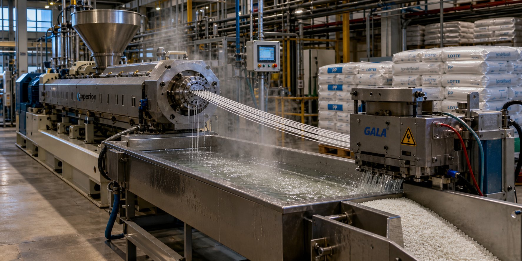
Pelletizing — the final step in most recycling and compounding lines — converts the homogenized melt into uniform granules through strand, underwater, or water-ring cutting systems. Whether the line functions as a dedicated screw extruder granulator or as part of a broader recycling train, the co-rotating platform's consistent die pressure and steady melt quality produce pellets with tight dimensional tolerances and uniform bulk density.
For operations requiring high-wear-resistant barrel and screw components in these demanding applications, suppliers such as NANHAIYA offer replacement and custom parallel twin screw barrels designed for stable conveying and mixing performance in compounding, masterbatch, recycling, and pelletizing environments.
Here is a consolidated view of how each application maps to the co-rotating features that enable it:
- Polymer compounding and filled systems — figure-eight distributive mixing disperses fillers and additives uniformly at controlled shear levels.
- Color masterbatch production — self-wiping action prevents cross-contamination and ensures narrow residence-time distribution for streak-free dispersion.
- Reactive extrusion — modular barrel length and multiple injection ports support in-barrel chemical reactions with consistent residence time.
- Devolatilization — reverse elements create melt seals for efficient vacuum venting of moisture, monomers, and solvents.
- Plastic recycling — intensive melting and degassing handle contaminated, variable-quality post-consumer feedstock.
- Pelletizing operations — steady melt pressure and temperature produce uniform granules through strand or underwater cutting systems.
Each of these processes relies on a carefully controlled feed of raw materials into the extruder — and the way material enters the barrel has a surprisingly large impact on everything that happens downstream. Most co-rotating systems do not simply gravity-flood the feed throat, and the reasons for that choice reveal another layer of process control.
Feed Systems and Starve Feeding Fundamentals
You have carefully designed your screw profile, selected the right L/D ratio, and mapped out your barrel temperature zones. Yet none of that engineering matters if the material entering the barrel arrives in the wrong quantity, at the wrong rate, or in the wrong location. How raw material is introduced into a twin screw extruder machine shapes fill level, mixing intensity, melt quality, and even die pressure stability — and the feeding strategy used in co-rotating systems is fundamentally different from what most people expect.
Starve Feeding vs Flood Feeding
If you have worked with single-screw extruders, you are accustomed to flood feeding: pellets pile into the hopper under gravity, the screw channel fills completely, and throughput is determined by screw speed. More rpm means more output. Simple.
Co-rotating twin-screw extruder machines work the opposite way. As a comprehensive review published in Advances in Polymer Technology confirms, corotating twin screw extruders "almost always employ metered starve feeding at the main hopper and any side feeders, because this allows intentional control of fill in each zone and prevents overfilling of the intermeshing screws." Instead of gravity dumping material in excess, a precision feeder meters pellets, powder, or flake into the feed throat at a controlled mass flow rate that is deliberately lower than the screw's maximum conveying capacity.
The result? The screw channels in the feed zone run only partially filled. There is open air space above the material bed, and the screw spins fast enough that it could theoretically move far more material than it receives. Throughput is no longer tied to screw speed — the feeder controls how much material enters, and the screw speed controls how intensely that material is mixed.
Why does this matter in practice? Imagine you are compounding a glass-fiber-reinforced nylon and your dispersion quality is not meeting specification. On a flood-fed machine, increasing screw speed to boost mixing also increases throughput, which may overwhelm your downstream pelletizer or shift your residence time. With starve feeding, you simply raise the screw rpm while keeping the feeder output constant. Mixing intensity goes up. Production rate stays the same. That independence is powerful.
Starve feeding delivers another practical benefit that operators quickly appreciate: significantly reduced pressure fluctuations at the die. In flood-fed systems, even minor variations in solid bed formation or melting behavior can cause surging — sudden spikes and dips in die pressure that create inconsistent extrudate dimensions. Under starve-fed conditions, the screw channels remain partially filled through most of the barrel length, with pressure building only in the final metering or restrictive elements near the die. This controlled, localized pressurization produces a stable, predictable output that simplifies downstream operations.
There is also an energy advantage. Research shows that specific power consumption in starve-fed operation is typically 10 to 20 percent lower than in flood-fed mode, because reduced fill levels decrease material resistance and viscous drag in the upstream channels. Less wasted energy upstream means more of the motor's work goes toward productive mixing and melting where it is actually needed.
Gravimetric vs Volumetric Feeders and Side Feeding
Since the feeder — not the screw — determines throughput in a starve-fed double screw extruder machine, choosing the right feeder type directly affects formulation accuracy, material cost, and product consistency. Two technologies dominate: volumetric and gravimetric.
A volumetric feeder meters material based on volume or feed rate. An auger or dosing disc rotates at a set speed, displacing a consistent volume of material per revolution. It is simpler, lower in cost, and perfectly adequate when material bulk density stays relatively constant and formulation tolerances are forgiving. Typical accuracy ranges from approximately 1.5 to 5 percent, depending on feeder design and material consistency.
A gravimetric feeder measures material by weight. A load cell continuously monitors the hopper mass, calculates the actual discharge rate in real time, and automatically adjusts the auger or disc speed to maintain the target feed rate. This closed-loop correction compensates for bulk density changes, hopper level effects, and material flow inconsistencies. Accuracy typically holds within plus or minus 1 percent of the target feed rate — a meaningful improvement when you are dosing expensive color concentrates, reactive additives, or tightly spec'd formulations where a half-percent deviation translates to scrap or off-spec product.
When should you choose one over the other? The decision usually comes down to cost sensitivity and formulation precision.
- Volumetric feeders — best for general-purpose additive dosing, free-flowing pellets with stable bulk density, applications where moderate accuracy is acceptable, and operations where lower equipment cost is a priority.
- Gravimetric feeders — required for tight formulation tolerances, expensive or specialty additives where overfeeding wastes money, processes demanding real-time material tracking and consumption data, and any application where bulk density varies (regrind, flake, powder blends).
Many compounding lines use both types simultaneously — a gravimetric feeder on the main polymer stream for precise rate control, and volumetric feeders on lower-cost additives where moderate accuracy is acceptable.
Not every ingredient belongs at the main feed throat, though. Side feeders — typically small single-screw or twin-screw crammer units mounted on a combination barrel section downstream — introduce materials directly into the already-molten polymer. As Kenneth Russell explains in Plastics Technology, feeding glass or carbon fibers through the main feed throat forces them through the high-shear melting zone, where kneading blocks would "essentially grind them into a powder," destroying the fiber aspect ratio that provides the reinforcement benefit. A side feeder bypasses the melting section entirely, introducing fibers into the melt where gentler narrow-disc kneading blocks can incorporate them with minimal attrition.
Side feeders serve several other critical roles beyond fiber protection:
- High-fill mineral loading — calcium carbonate or talc at concentrations above 40 percent can starve the feed throat and interfere with polymer melting if introduced all at once. Side feeding splits the filler addition into a manageable downstream step.
- Low-melting additives — waxes, slip agents, and other ingredients with melting points far below the polymer's softening temperature can lubricate unmelted pellets and prevent proper melting. Feeding them downstream after the polymer is fully molten avoids this interference.
- Shear-sensitive additives — certain flame retardants, foaming agents, and thermally unstable components degrade when exposed to the intense mechanical energy of the melting zone. Downstream introduction protects them.
- Liquid injection — pumps deliver liquid additives, plasticizers, or reactive monomers directly into the melt through injection ports, bypassing the feed throat entirely. The liquid pressure must exceed local melt pressure to prevent polymer backflow into the injector.
In every case, the screw configuration beneath the side-feed port uses large-pitch conveying elements — the same open-channel geometry found at the main feed throat — to accept incoming material without creating a bottleneck. Mixing elements immediately downstream then incorporate the added ingredients at the appropriate shear intensity for the material type.
Getting the feed system right is foundational, but its importance amplifies during one of the most challenging phases of any extrusion project: scaling a proven formulation from a small laboratory twin screw extruder machine to a full-production line. The rules governing that transition are not as straightforward as simply building a bigger machine.
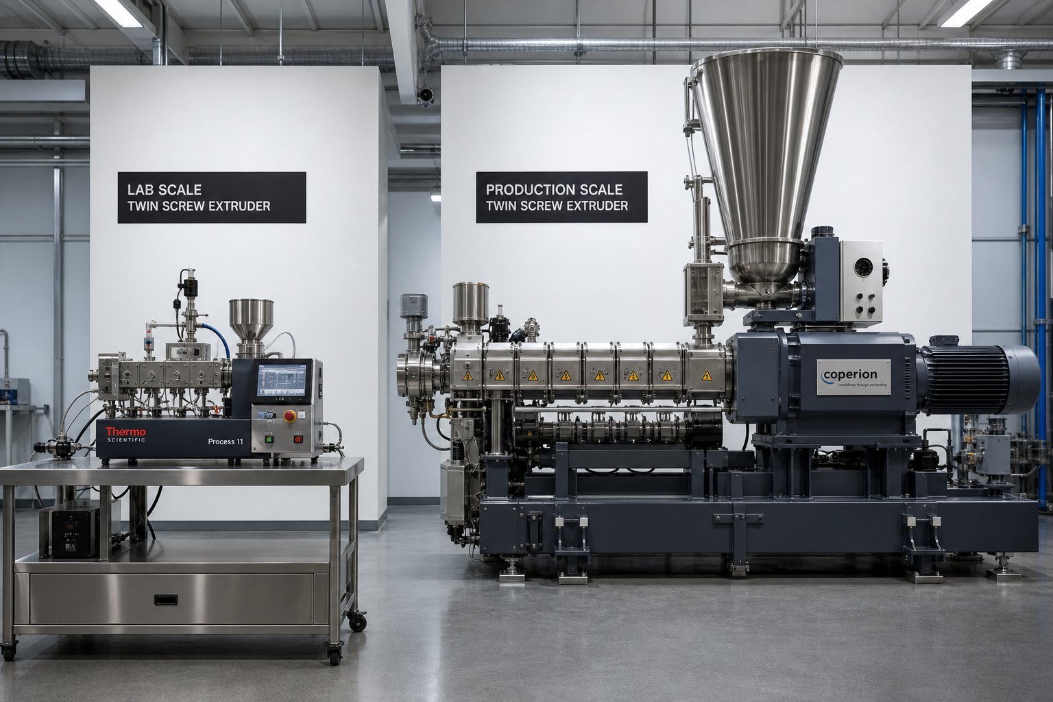
Scaling Up from Laboratory to Production Extruders
A formulation that runs beautifully on a 26 mm laboratory twin screw extruder does not automatically behave the same way on a 92 mm production machine. The screws are geometrically similar, the element sequence matches, the temperature profile is identical — and yet the melt comes out unmixed, with unmelted pellets visible in the discharge. What went wrong?
Scale-up is one of the most misunderstood steps in twin screw extrusion. Engineers who have perfected a process on a benchtop twin screw extruder sometimes assume that multiplying the throughput is simply a matter of building a bigger version of the same machine. In reality, the physics change as the diameter grows, and the parameters that kept your lab process stable may leave your production extruder starved of energy. Understanding why — and knowing which parameters to preserve — separates a smooth commercialization from weeks of troubleshooting on the factory floor.
Geometric Similarity and Dimensionless Parameters
The foundation of any twin screw scale-up is geometric similarity. This means the target production extruder and the reference laboratory machine share the same proportional screw geometry: identical outer-diameter-to-inner-diameter (OD/ID) ratios, the same L/D ratio, and an equivalent screw element sequence scaled proportionally to the new diameter. A case study published in Plastics Technology illustrates this principle clearly — 26 mm, 40 mm, and 92 mm co-rotating extruders were all built with an L/D of 44 and an OD/ID ratio of 1.55, ensuring that the channel geometry, intermesh clearances, and element proportions remained consistent across all three scales.
With geometric similarity established, the next question is: how much more throughput can the larger machine handle? For processes that are not limited by heat transfer or devolatilization, volumetric throughput scales roughly with the cube of the diameter ratio:
Qtarget = Qreference × (Dtarget / Dreference)3
The logic is straightforward — the free volume inside the screw channels increases in three dimensions as the diameter grows. A practical example from Plastics Today puts numbers to the concept: if a 27 mm machine produces 100 kg/hr, a geometrically similar 75 mm extruder can theoretically reach approximately 2,148 kg/hr — a factor of (75/27)3, or about 21.5 times the lab rate.
But throughput alone does not define a successful scale-up. The critical parameter engineers must match is specific mechanical energy (SME) — the energy per unit mass transferred from the motor through the screws and into the material, expressed in kWh/kg. SME captures the combined effect of screw speed, torque, and feed rate in a single number that directly correlates with melt quality. In the Plastics Technology case study, the optimized SME on the 26 mm laboratory twin screw extruder was 0.083 kWh/kg. Whenever subsequent scale-up trials on the 40 mm and 92 mm machines matched that SME value, the process produced stable, homogeneous melt with consistent pellet quality. Whenever the SME diverged — dropping to 0.055 kWh/kg on the 40 mm or a critically low 0.026 kWh/kg on the 92 mm — the result was phase separation, pressure surging, and even unmelted pellets discharging from the extruder.
Preserving geometric similarity and matching SME are the two non-negotiable anchors of the scale-up process. Every other adjustment — screw speed, temperature profile, element rearrangement — serves the goal of bringing SME on the target machine in line with the proven reference value.
What Changes During Scale-Up
If geometric similarity and the cube-law throughput equation were the whole story, scale-up would be simple arithmetic. In practice, several physical relationships shift as extruder diameter increases, and ignoring them leads to the exact failures described above.
Surface-to-volume ratio drops dramatically. A small-diameter barrel has a large surface area relative to the melt volume inside it. This means barrel heaters and cooling channels exert strong control over melt temperature — the heat does not have far to travel to reach the core of the material. As the diameter increases, the volume of material grows with the cube of the diameter, but the barrel surface area grows only with the square. The result? Barrel wall cooling becomes progressively less effective at removing viscous dissipation heat from the melt core. A kneading block configuration that ran comfortably on a 26 mm machine with mild cooling may overheat the melt center on a 92 mm machine even with maximum coolant flow. The Plastics Technology case study confirmed this directly: a raw material creating a lubricating effect along the barrel wall — a phenomenon that was negligible on the small-scale machine — became process-breaking at the 92 mm scale because the reduced area-to-volume ratio limited the shear stress transferred to the melt.
Residence-time distribution shifts. Larger channel depths and altered flow patterns change how material moves through the barrel. The degree of screw fill, which is tightly controlled at lab scale, becomes harder to predict at production scale because feed dynamics, side-stuffer behavior, and vent-port interactions all scale differently. Engineers must re-evaluate fill levels and verify that the residence-time distribution remains narrow enough to avoid thermal degradation on the long end or incomplete mixing on the short end.
Torque density becomes the mechanical ceiling. Torque density — the maximum torque transmitted per unit of screw shaft cross-sectional volume, typically expressed in Nm/cm3 — determines how much mechanical energy the gearbox and shaft can deliver to the process. Modern high-torque extruder designs have steadily increased this parameter through improved shaft metallurgy and spline geometry, reaching values above 10 Nm/cm3 in current-generation platforms. Higher torque density means a given-diameter machine can run more aggressive screw configurations or process higher-viscosity materials without exceeding the mechanical limits of the drive train. During scale-up, verifying that the target machine's torque density supports the required SME at the planned throughput and screw speed is essential — otherwise, the motor runs at or near maximum load with no headroom for process adjustments.
Successful scale-up requires matching specific mechanical energy input and mixing quality between the reference and target machines — simply achieving the target throughput rate is not enough to guarantee equivalent product quality or process stability.
The practical lesson from real-world scale-up campaigns is sobering. Even with perfectly matched geometry, identical element sequences, and the same temperature profile, both the 40 mm and 92 mm extruders in the Plastics Technology study required screw design adjustments, cooler temperature profiles, and modified screw speeds before they could replicate the SME and product quality established on the lab machine. The cube-law equation predicted the achievable throughput — a 3.64-fold increase from 26 mm to 40 mm and a 12.17-fold increase from 40 mm to 92 mm — but those rates were only realized after iterative process optimization at each scale.
For heat-transfer-limited processes, the scale-up exponent drops closer to 2 instead of 3, meaning throughput increases with the square of the diameter ratio rather than the cube. Devolatilization-intensive processes typically fall between 2.3 and 2.7, because surface renewal and vapor disengagement depend more on exposed melt area than on channel volume. Knowing which regime your process falls into — power-limited, heat-transfer-limited, or surface-area-limited — before committing to a production machine size saves both capital and commissioning time.
Whether you are moving from a benchtop twin screw extruder running at 5 kg/hr to a pilot-scale 40 mm platform, or jumping from pilot to a full-production 92 mm or larger line, the discipline is the same: preserve geometric similarity, match SME, respect the changing physics of heat transfer and fill, and validate at every intermediate scale rather than leaping directly from lab to factory. That disciplined approach protects the investment — but even the best-scaled process eventually encounters wear, fouling, or configuration drift that erodes performance over time.
Troubleshooting and Maintaining Twin Screw Barrel Performance
Wear, fouling, and configuration drift do not announce themselves with a single dramatic failure. They creep in — a slow widening of pellet size distribution, a gradual uptick in motor load, a faint discoloration that was not there last quarter. The challenge is connecting those symptoms to root causes before they cascade into costly downtime. Equally important is knowing when your twin screw barrel has crossed the line from "still serviceable" to "quietly destroying your product quality."
Troubleshooting Common Processing Issues
Most co-rotating parallel twin screw extruder problems fall into a handful of recurring patterns. The trick is resisting the urge to adjust barrel temperatures at random and instead diagnosing whether the issue originates in the screw configuration, the feed system, or the process parameters. Here are the most frequent culprits and the fixes that address the actual root cause rather than masking the symptom.
| Problem | Likely Root Cause | Recommended Configuration or Process Fix |
|---|---|---|
| Surging (inconsistent output) | Improper screw configuration creating unstable melt seals; feeder output fluctuations; flood feeding instead of starve feeding | Verify feeder calibration and switch to gravimetric control if using volumetric. Check that reverse elements or neutral kneading blocks create a stable melt seal upstream of the metering zone. Reduce screw speed if fill levels are excessive in the feed section. |
| Die drool (polymer buildup at die lips) | Excessive die pressure forcing low-molecular-weight fractions or degraded material to the die face; moisture or volatiles not fully removed upstream | Add or extend a vacuum devolatilization zone upstream of the metering section. Reduce die-zone barrel temperature slightly to increase melt viscosity at the exit. Polish die land surfaces and verify die gap uniformity. |
| Thermal degradation (discoloration, gels, black specks) | Excessive residence time from over-restriction in the screw profile; stagnant zones caused by worn self-wiping clearances; barrel temperature set too high in the melt zone | Shorten or remove unnecessary restrictive elements (reverse kneading blocks, 90-degree neutral blocks) to reduce hold-up time. Increase throughput relative to screw speed to raise fill and reduce the time any given polymer particle spends in the barrel. Inspect twin screw and barrel clearances for wear-related dead zones. |
| Poor filler dispersion (agglomerates, uneven color) | Insufficient dispersive mixing energy; kneading block stagger angles too mild; filler introduced too far downstream with inadequate remaining mixing length | Replace narrow-disc kneading blocks with wider discs or increase stagger angle from 30 degrees to 60 degrees in the dispersion zone. Move the filler side-feed port upstream to allow more mixing barrel length. Increase screw speed while holding feed rate constant to boost specific energy input. |
Notice a common thread? Nearly every fix involves adjusting the relationship between screw elements and process parameters — not simply turning a single dial. Surging, for example, tempts operators to slow the screw speed, which may reduce output fluctuations momentarily but also drops specific energy input and can worsen filler dispersion downstream. A systematic approach starts with the feeder, verifies the melt seal, and adjusts screw speed only as a final calibration step.
Barrel and Screw Wear Patterns and Replacement
Even a perfectly configured screw profile degrades over time, and the rate of that degradation depends heavily on what you are processing. Abrasive fillers — calcium carbonate, glass fiber, titanium dioxide — act like sandpaper against the barrel bore and screw flight surfaces. Corrosive polymers and reactive additives attack the metal chemically, especially under the extreme temperatures and pressures found in the melting and mixing zones. As industry analysis from HAISI Extrusion details, four primary high-wear zones exist inside a twin screw barrel: the feeding section where solid particles abrade the bore wall, the filler introduction zone where sheared glass fibers generate razor-sharp fragments, the middle barrel section where axial pressure causes screw deflection and barrel scraping, and the discharge zone where the cantilevered screw end sags under gravity.
The consequences of wear are insidious. As the clearance between screw flight tips and barrel bore widens, the self-wiping mechanism loses efficiency. Material begins to stagnate in the growing gap, creating the exact dead zones the co-rotating geometry was designed to prevent. Melt leakage backward across worn flight tips reduces forward pumping efficiency and broadens the residence-time distribution. Mixing performance drops because the tight tolerances that enable dispersive shear no longer exist. You may see the effects as gradually worsening filler dispersion, increasing specific energy consumption for the same throughput, or a subtle rise in die pressure variability — all symptoms that mimic configuration problems but actually originate in hardware condition.
Monitoring barrel bore diameter at regular intervals is the single most reliable way to track wear progression and make informed replacement decisions. A bore gauge inserted at multiple axial positions reveals how quickly the clearance is opening and which zones are deteriorating fastest. Twin screw extruder manufacturers typically specify a maximum allowable bore wear — often around 0.2 mm beyond nominal diameter — beyond which mixing and conveying efficiency fall below acceptable levels.
Here are the warning signs that your twin screw barrel needs replacement or refurbishment:
- Bore diameter exceeds the manufacturer's wear limit — measured at high-wear zones (feed section, filler introduction, and discharge), indicating loss of self-wiping clearance and mixing efficiency.
- Increasing specific energy consumption — the motor works harder to achieve the same throughput and melt quality, signaling reduced screw-to-barrel sealing and more internal melt leakage.
- Declining filler or pigment dispersion quality — agglomerates or streaks reappear despite no change in screw configuration or operating parameters.
- Wider residence-time distribution — changeover times between formulations grow longer because worn clearances allow material to linger in expanded dead zones.
- Visible scoring or grooving on the barrel bore — deep scratches from abrasive fillers or foreign-object damage that cannot be polished out and will accelerate further wear.
- Elevated melt temperature at constant barrel set points — worn clearances increase viscous dissipation in the flight-tip gap, heating the melt beyond the intended processing window.
Selecting the correct barrel metallurgy and screw element material grade is as important as the initial machine selection for long-term production consistency. Standard nitrided steel barrels serve well for unfilled or lightly filled polymers, but heavily abrasive formulations demand bimetallic liners or powder metallurgy (PM) steel — a material that offers finer grain structure, superior hardness, and longer service life under extreme wear conditions. For compounding producers, masterbatch manufacturers, recycling plants, and pelletizing operations requiring replacement or custom-engineered parallel twin screw barrels, NANHAIYA provides barrels designed for stable conveying, effective mixing, and resistance to high-wear processing conditions — a critical consideration when barrel quality directly determines how long your screw profile retains its intended performance characteristics.
Ultimately, a co-rotating parallel twin screw extruder is only as good as the weakest link in its processing chain. The self-wiping geometry, modular screw elements, and starve-fed control architecture give you extraordinary flexibility — but that flexibility depends on tight mechanical tolerances maintained through disciplined monitoring, timely component replacement, and material-grade selection matched to the severity of your application. Keep the twin screw and barrel in specification, and the machine will reward you with the consistent, high-quality output that made it the dominant platform from lab bench to factory floor.
Frequently Asked Questions About Co-Rotating Parallel Twin Screw Extruders
1. What is the difference between co-rotating and counter-rotating twin screw extruders?
Co-rotating twin screw extruders have both screws spinning in the same direction, enabling self-wiping action, high-speed operation (up to 1,000+ rpm), and intense distributive mixing through a figure-eight flow pattern. Counter-rotating designs turn screws toward each other, creating a calendering nip that generates higher discharge pressure but limits screw speed to roughly 50 rpm and produces lower throughput. Co-rotating machines dominate compounding and reactive extrusion, while counter-rotating systems are preferred for rigid PVC and thermally sensitive polymers requiring gentle, low-shear processing.
2. Why do co-rotating twin screw extruders use starve feeding instead of flood feeding?
Starve feeding decouples screw speed from throughput, giving operators independent control over mixing intensity and production rate. A metering feeder delivers material below the screw's maximum conveying capacity, keeping channels partially filled. This reduces die pressure fluctuations, cuts specific power consumption by 10 to 20 percent compared to flood feeding, and allows engineers to increase mixing energy by raising screw speed without changing output rate — a level of process control that flood-fed systems cannot achieve.
3. How do you select the right L/D ratio for a twin screw extruder?
L/D ratio selection depends on process complexity. Shorter ratios of 32:1 to 36:1 suit straightforward compounding like color masterbatch and simple additive blending. Longer ratios of 40:1 to 52:1 are necessary for reactive extrusion, multi-stage devolatilization, or formulations with multiple downstream injection and side-feed points. However, unnecessary barrel length adds thermal history and shear load, which can degrade heat-sensitive polymers. The best practice is choosing the shortest L/D that accommodates all required processing zones.
4. What causes surging in a co-rotating twin screw extruder and how do you fix it?
Surging — inconsistent output causing pressure spikes and dips at the die — typically stems from unstable melt seals in the screw profile, feeder output fluctuations, or flood feeding instead of starve feeding. Effective fixes include switching to gravimetric feeder control for precise rate regulation, verifying that reverse elements or 90-degree kneading blocks form a stable melt seal upstream of the metering zone, and reducing screw speed if fill levels are excessive. A systematic approach starts at the feeder and works downstream rather than adjusting barrel temperatures at random.
5. When should you replace the barrel on a twin screw extruder?
Barrel replacement is warranted when bore diameter exceeds the manufacturer's specified wear limit — typically around 0.2 mm beyond nominal — measured at high-wear zones such as the feed section, filler introduction area, and discharge. Other indicators include rising specific energy consumption at constant throughput, declining filler or pigment dispersion quality, longer changeover times between formulations, and elevated melt temperatures at unchanged barrel set points. For abrasive or corrosive applications, suppliers like NANHAIYA (nhyscrews.com) offer bimetallic and custom-engineered parallel twin screw barrels designed to extend service life under demanding processing conditions.
Written by
Nanhaiya Technical Team
Zhoushan Nanhaiya Plastic Machinery Co., Ltd.
The Nanhaiya technical team supports screw and barrel manufacturing projects through application review, technical communication, custom manufacturing coordination, and production and quality control.
Discuss Your Application
Related Articles
More insights on screw barrel technology and plastics processing.

What Nobody Tells You About Screw Barrel For Plastic Machine Design
Oct 10, 2026
Learn how screw barrel for plastic machine design affects melt quality, throughput, and wear life. Covers geometry, resin matching, troubleshooting, and sourcing.
Read Article
Single Screw Extruder for Sheet: Stop Guessing, Start Specifying
Oct 9, 2026
Learn how to specify a single screw extruder for sheet production. Covers screw geometry, resin-specific processing, troubleshooting, and maintenance best practices.
Read Article
PE Pipe Extruder Machine: What Datasheets Won't Tell You
Oct 9, 2026
Learn how a PE pipe extruder machine works, key specs explained, material grade selection, maintenance tips, and buyer guidance beyond the datasheet.
Read ArticleLooking for something else?
Search by material, symptom or product and jump straight to the relevant page.
These are navigation suggestions based on keyword matching — not a quotation, not a delivery commitment, and not a substitute for engineering review. Final specification is confirmed by our engineers against your drawings and processed material.
Need help with screw barrel selection?
Share your machine model, processed material and application. Our team can help with pricing and technical support.