

What Is a Conical Twin Screw Extruder Design
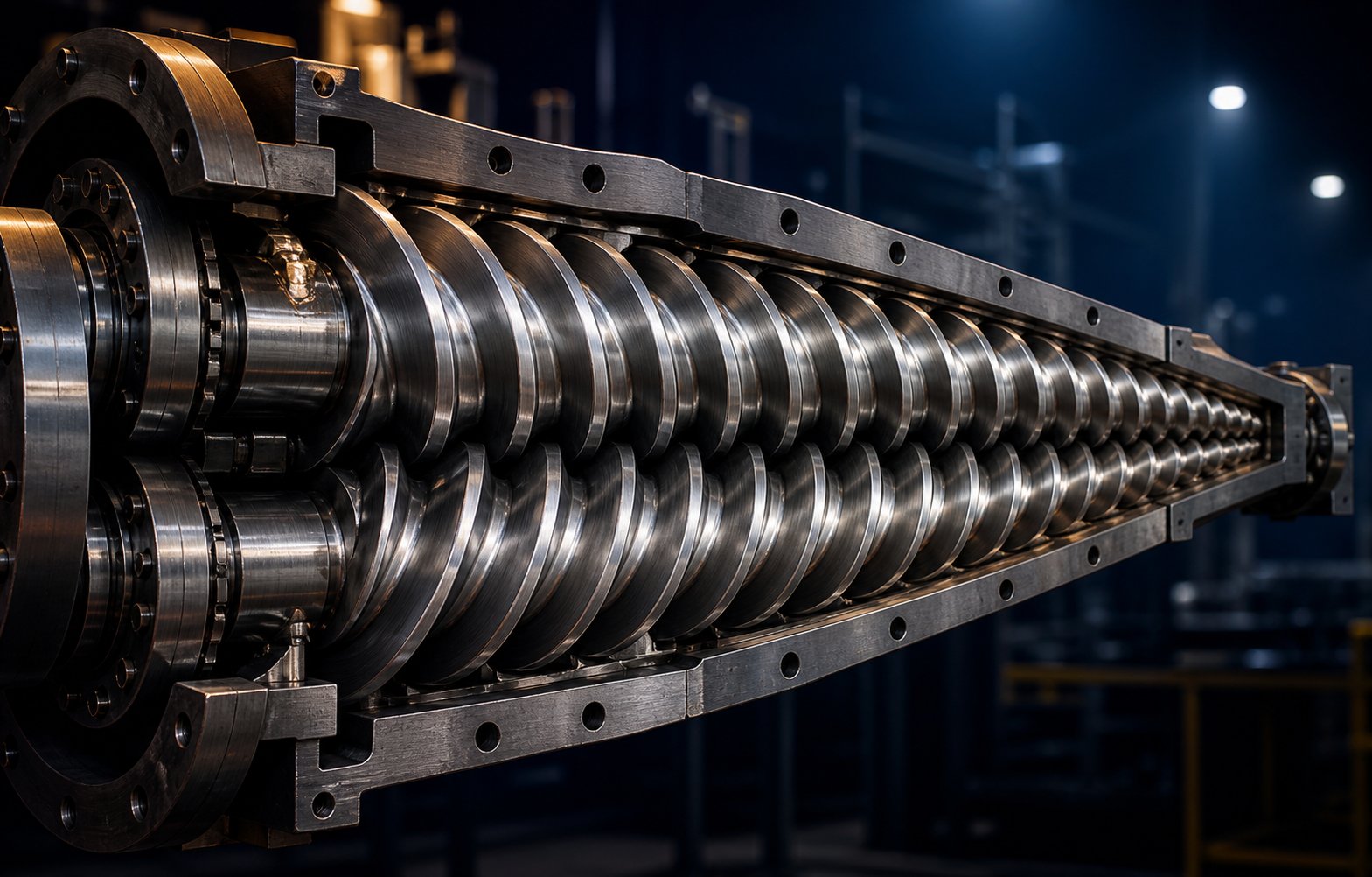
Imagine two screws that aren't cylinders but cones, wide at one end and narrow at the other, meshing together inside a barrel that mirrors their taper. That single geometric idea separates a conical twin screw extruder from every other twin-screw extruder on the market, and it shapes nearly every processing advantage the machine delivers.
Defining the Conical Twin Screw Extruder
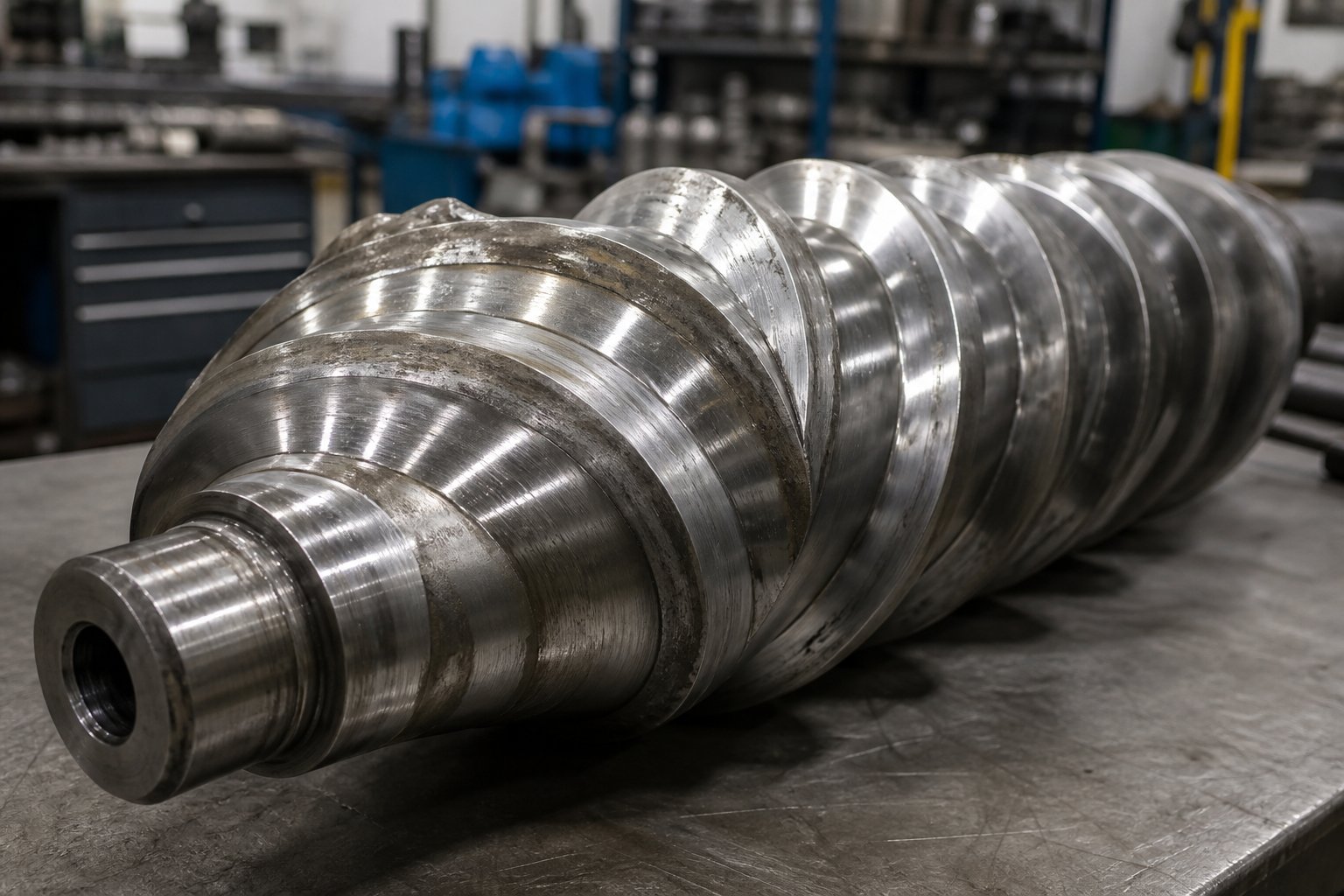
A conical twin screw extruder design uses a pair of tapered, counter-rotating intermeshing screws housed in a converging barrel. The screw diameter is larger at the feed end and progressively decreases toward the discharge end, creating a natural compression zone that melts, mixes, and pressurizes material without relying on aggressive screw elements.
This definition highlights what makes the design fundamentally different from a parallel twin screw extruder, where both screws maintain a uniform diameter from feed to die. In a conical configuration, the decreasing channel volume along the screw length does much of the compression work automatically. Powder or granular material enters the wider feed section, gets conveyed forward by the rotating flights, and encounters a steadily shrinking space that compresses and plasticizes it before it reaches the discharge end.
You'll notice that this taper also affects how the screws interact with each other. Because the axes of the two screws converge rather than run parallel, there is more room at the feed end for larger root diameters, bigger bearings, and a more robust gearbox connection. That extra space translates directly into higher torque capacity, a critical factor when processing stiff, high-viscosity formulations like rigid PVC compounds.
Why Design Geometry Matters in Extrusion
Why should you care about the shape of the screws? Because geometry drives three outcomes that define extruder performance:
- Natural compression. The taper creates a built-in compression ratio. Material is progressively squeezed as it travels toward the smaller-diameter discharge zone, reducing the need for restrictive mixing elements that can generate excessive shear heat.
- High torque transmission. The wider feed end accommodates larger drive components, giving the twin-screw extruder machine significantly more torque per unit of output diameter compared to parallel designs of similar throughput.
- Gentle material handling. At the discharge end, the smaller screw diameter means lower circumferential speed and reduced shear rate, which keeps heat-sensitive polymers like PVC well below their degradation threshold.
These three characteristics aren't accidental perks. They are direct, predictable consequences of the conical geometry, and they explain why this type of twin screw extruder has remained the workhorse for PVC pipe, profile, and sheet extrusion for decades.
Most guides on this topic stop at a surface-level comparison chart. This article takes a different approach. Every section that follows examines conical twin screw extruder design from first-principles engineering: how the taper generates compression, why counter-rotation dominates, what the gearbox geometry really looks like, where wear patterns develop, and how modern metallurgy is extending service life. The goal is to give you the foundational understanding that turns equipment specs into actionable processing knowledge.
That engineering story begins with the simplest question: how does a tapered barrel actually build pressure?
How Conical Geometry Creates Natural Compression
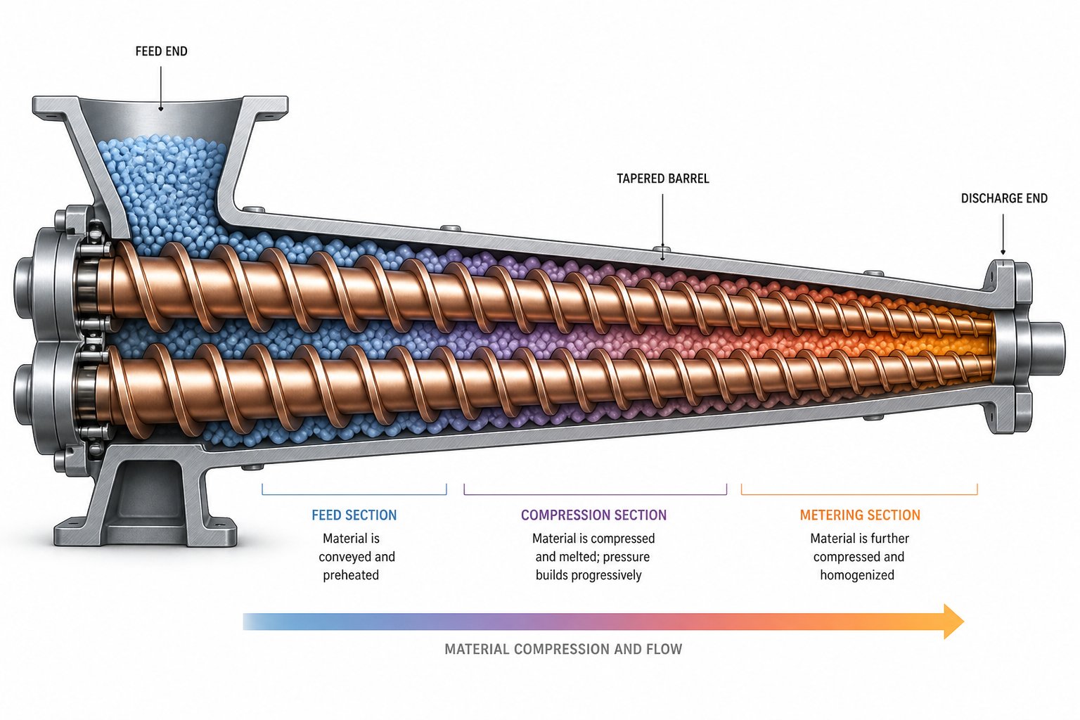
Picture a funnel. Pour loose material into the wide end, and by the time it reaches the narrow end, it has been compressed into a denser mass without any mechanical squeezing device. A conical twin screw extruder design applies exactly this principle, only with precision-engineered taper angles, rotating flights, and controlled thermal input turning a simple geometric concept into a highly efficient plasticizing system.
How Taper Geometry Drives Compression
The key lies in what happens to channel volume as material moves along the extruder screws. At the feed end, the large screw diameter creates wide, deep channels that accept bulky powders and granules easily. As the screws taper toward the discharge end, the channel cross-section shrinks progressively. Material occupying a given length of screw channel at the feed zone is forced into a smaller volume just a few turns later.
This volume reduction is governed by the taper angle, which in most commercial conical designs falls within a range of roughly 1 to 3 degrees per side. Sounds small? It is, but even a modest taper applied over the full screw length produces a substantial compression ratio. For rigid PVC dry blends, which enter the feed zone with a bulk density far below their melt density, this built-in compression is essential for consolidating loose powder into a homogeneous melt efficiently.
The compression ratio itself is determined by the ratio of the feed channel volume per unit length to the metering channel volume per unit length. A steeper taper compresses material more aggressively, which suits low-bulk-density feedstocks. A gentler taper provides a more gradual transition, reducing the risk of excessive pressure spikes when processing denser granules. Manufacturers typically customize this ratio to match specific polymer formulations, accounting for differences in bulk density, melt viscosity, and additive loading.
Pressure Generation Toward the Discharge End
Compression and pressure generation are closely related but not identical. Compression densifies the material. Pressure generation pushes it through the die. In a conical twin screw system, both happen simultaneously along the taper, and that is a significant engineering advantage.
As the converging barrel narrows, the increasingly dense melt has fewer places to go. The shrinking channel forces material forward against the resistance of the die at the discharge end, building melt pressure progressively along the screw length. This means the die sees a steady, well-developed pressure profile rather than a sudden pressure spike generated by a single restrictive element. The result is more consistent melt delivery, lower pulsation at the die lip, and better dimensional stability in the final extruded product, whether it is a pipe, profile, or sheet.
Industry data supports this advantage. Conical twin screw extruders operating on rigid PVC typically run at just 20 to 50 rpm, yet they build sufficient die pressure to produce output rates of 200 to 800 kg/h depending on screw diameter selection. The geometry does the heavy lifting, not the speed.
Compression Without Aggressive Screw Elements
Here is where the contrast with parallel twin screw designs becomes sharpest. In a parallel extruder, both screws maintain a constant diameter from feed to discharge. There is no inherent volume reduction along the barrel. To achieve compression, processors must configure the screw profile with specific elements, such as reverse-pitch conveying segments, kneading blocks, or narrow-pitch metering sections, that deliberately restrict forward flow and build localized pressure.
These restrictive elements are effective, but they come with a tradeoff: concentrated shear energy. Every kneading block and reverse element converts mechanical energy into heat at a specific point along the barrel. For shear-tolerant engineering polymers, that is perfectly acceptable. For heat-sensitive materials like PVC, which begins to degrade at temperatures above approximately 200 degrees Celsius, those localized hot spots become a serious processing risk.
The conical approach sidesteps this problem. Because the taper provides compression across the entire screw length rather than at discrete points, shear energy is distributed more evenly. The twin screw channels do not need aggressive mixing elements to build pressure, so frictional heat generation stays low. This distributed energy input is a core reason why conical designs consistently achieve lower melt temperatures and better thermal uniformity than parallel configurations processing the same material.
Think of it this way: a parallel design uses engineered obstacles to create pressure. A conical design uses engineered geometry. One fights the material flow to compress it; the other guides the material flow into a naturally narrowing space. The downstream consequence of this distinction is profound, and it extends directly into how the two screw types rotate and convey material through the barrel.
The Counter-Rotating Intermeshing Mechanism Explained
Geometry shapes compression. Rotation direction shapes conveying. In a conical twin screw extruder, these two principles work in concert, and understanding how they interact explains why counter-rotation is not merely a preference for this machine type but a near-universal standard.
Positive Displacement Conveying in Conical Barrels
Imagine two gears meshing together, each tooth trapping a fixed volume of fluid and carrying it from one side to the other. A counter-rotating intermeshing twin screw extrusion system works on a strikingly similar principle. When the two tapered screws turn in opposite directions, their intermeshing flights create a series of closed, C-shaped chambers between the screw flights and the barrel wall. Each chamber captures a discrete pocket of material, seals it off from the chambers ahead and behind, and physically pushes it forward as the screws rotate.
This is positive displacement conveying. The volume of material moved per revolution depends almost entirely on the chamber geometry and screw speed, not on the frictional or viscous properties of the material itself. Whether the feedstock is a free-flowing PVC dry blend or a sticky wood-plastic composite powder, the conveying rate stays predictable. That independence from material rheology is a major operational advantage, especially when processing formulations with variable bulk density or inconsistent flow behavior.
The converging barrel amplifies this effect. As the C-shaped chambers travel along the taper toward the discharge end, their volume shrinks progressively. Material trapped in each chamber cannot slip backward because the intermeshing flights behind it form a physical seal. It cannot expand sideways because the barrel wall is closing in. The only path is forward, and the shrinking space ensures that material is simultaneously conveyed and compressed in a single, smooth action.
Counter-Rotation vs Co-Rotation for Conical Designs
Why not use co-rotating screws in a conical barrel? To answer that, you need to look at how the two configurations handle material flow at the intermeshing zone.
In a co-rotating twin screw extruder, both screws turn in the same direction. Material at the intermeshing region is handed off from one screw to the other in a figure-eight pattern. The screw channels remain open longitudinally, meaning material can flow both forward and backward along the channel. Conveying in this configuration relies heavily on drag flow, where friction between the material and the barrel wall drags the melt forward. The result is excellent mixing intensity but less precise volumetric control over throughput.
Counter-rotating screws reverse this dynamic entirely. At the intermeshing point, the two screws draw material inward between them and push it forward. The flights of each screw effectively block the channel of the opposite screw, creating those closed C-shaped chambers that enable true positive displacement. Material transport depends on screw rotation itself rather than on the frictional behavior of the polymer.
For conical geometry, counter-rotation is the natural fit for three reasons:
- Sealed chambers complement the taper. The closed C-shaped pockets work with the converging barrel to create a progressive, controlled compression. Co-rotating open channels would partially defeat the taper's compression advantage by allowing backflow.
- Low-speed, high-torque operation. Counter-rotating conical extruders typically run at 15 to 50 rpm, far below the 200 to 1,200 rpm common in co-rotating parallel machines. The positive displacement mechanism maintains stable output even at these low speeds, while the large feed-end diameter accommodates the heavy-duty gearbox needed for high torque.
- Stable pressure output. Because each chamber delivers a fixed volume, melt pressure at the die fluctuates less. This translates to tighter dimensional tolerances on extruded pipes and profiles.
Gentle Mixing Through Intermeshing Flight Geometry
Mixing and conveying are always a balancing act in twin screw extrusion. Co-rotating designs excel at dispersive mixing, the kind that breaks apart filler agglomerates and distributes additives at a microscopic level through intense shear fields. That capability is essential for compounding engineering plastics, but it generates substantial frictional heat, a serious liability when processing thermally sensitive polymers.
Counter-rotation in a converging barrel produces a fundamentally different mixing mechanism. At the intermeshing region, a calendering effect takes over: material is drawn between the two screws like dough passing through a rolling mill, undergoing compressive and elongational deformation rather than high-shear cutting. This calendering action gently folds and redistributes the melt, achieving distributive mixing, where components are spread evenly throughout the matrix, without the intense energy input that would trigger degradation in materials like rigid PVC.
The practical outcome is clear. A co-rotating twin screw extruder might process PVC only to see yellowing, off-gassing, and property loss from thermal decomposition. A counter-rotating conical machine handles the same formulation at lower melt temperatures, preserving the polymer's molecular structure while still achieving thorough additive dispersion. The low shear stress and gentle calendering make counter-rotating conical extruders the dominant choice for PVC pipes, profiles, and sheets, as well as wood-plastic composites that contain both heat-sensitive polymers and abrasive fillers.
This distinction between rotation modes explains the processing behavior. But how does the conical design stack up against its parallel counterpart across a broader set of engineering parameters? The answer involves far more than just rotation direction.
Conical vs Parallel Twin Screw Extruder Design Compared
Rotation direction tells part of the story. Screw geometry, compression strategy, torque handling, modularity, and throughput capacity fill in the rest. When you place a conical counter-rotating design next to a parallel co-rotating double screw extruder, the two machines look like they were built for entirely different jobs, and in many respects, they were. Rather than declaring one superior to the other, a clear-eyed comparison across the parameters that actually matter helps you match the right architecture to the right application.
Screw Geometry and Compression Compared
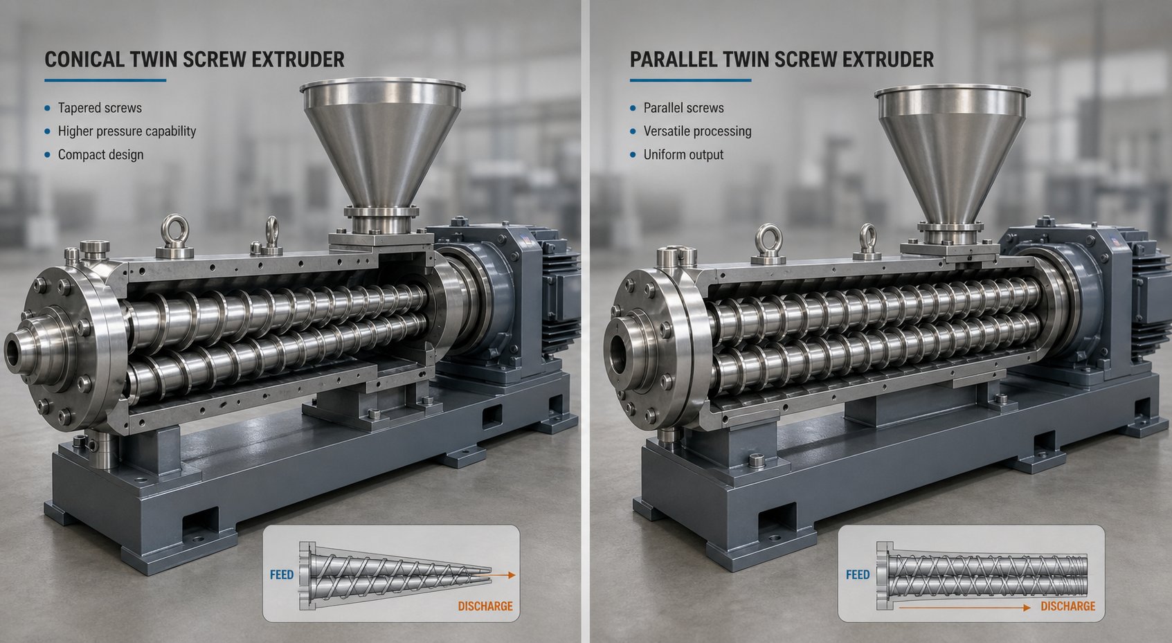
The most visible difference is the screws themselves. A conical machine uses a pair of tapered screws that decrease in diameter from the feed end to the discharge end, housed in a converging barrel. A parallel machine uses screws of uniform diameter along their entire length, seated in a constant-bore barrel. This single distinction cascades into almost every aspect of performance.
In the conical layout, compression is a geometric inevitability. The shrinking channel volume does the densification work continuously along the barrel length, producing a smooth, progressive pressure rise. In a parallel twin screw extruder, the uniform barrel bore provides no inherent volume reduction. Compression depends entirely on how the screw profile is configured: kneading blocks, reverse-pitch elements, and narrow-pitch metering sections must be strategically placed to create localized pressure zones. This gives the parallel design enormous flexibility but also introduces concentrated shear points, a tradeoff that matters greatly when processing heat-sensitive polymers.
Torque capacity follows directly from screw geometry. Because the conical screws diverge toward the feed end, there is physically more room between the screw axes at the drive connection. That extra space allows larger bearings, bigger shaft diameters, and a more robust gearbox, all of which translate into higher torque transmission per unit of output-end cross-section. Parallel twin screw extruders face a fundamental constraint here: the fixed center distance between screw axes limits bearing size and, by extension, the maximum torque the gearbox can deliver. Manufacturers of parallel machines have responded with increasingly sophisticated gearbox engineering, pushing torque densities above 10 Nm/cm3 in premium models, but the constraint remains geometric.
Modularity and Application Flexibility
Here is where the parallel design pulls decisively ahead. Most parallel co-rotating twin screw extruders use segmented, modular screw and barrel construction. Individual screw elements, conveying segments, kneading blocks, mixing elements, and distributive mixing discs, slide onto a common splined shaft and can be rearranged in minutes. Barrel sections can be swapped to add side feeders, vacuum vents, or liquid injection ports at different positions along the length.
This modularity makes a single parallel machine adaptable to dozens of different formulations and processes. Need to compound glass-fiber-reinforced nylon today and a color masterbatch tomorrow? Reconfigure the screw profile and barrel layout. That kind of flexibility is why parallel co-rotating twin screw extruders dominate in compounding operations, research laboratories, and facilities that handle a broad product portfolio.
Conical designs take the opposite approach. The tapered screws are typically one-piece constructions, machined as a single unit. The barrel is a one-piece or two-piece converging housing. You cannot rearrange elements or add venting ports at arbitrary locations. The geometry is fixed at manufacture, optimized for a specific material family and processing window. This makes conical machines less versatile but highly efficient for dedicated production lines where the same formulation runs continuously, exactly the scenario in PVC pipe and profile extrusion plants.
Throughput range further separates the two architectures. Parallel co-rotating twin screw extruders scale broadly. Small laboratory models handle a few kilograms per hour, while large production machines push throughput beyond 20,000 kg/h for high-volume compounding. Conical machines typically operate in a narrower throughput band, commonly 200 to 800 kg/h for rigid PVC applications, constrained by the fixed taper geometry and the lower screw speeds inherent to counter-rotating operation.
Machine footprint offers a counterpoint. The converging screw layout in a conical extruder means the barrel is shorter and more compact than a parallel barrel of equivalent output capacity. For processors working in space-constrained facilities, the smaller footprint of a conical double screw extruder can be a practical advantage.
Conical vs Parallel Comparison Table
The following table consolidates these differences across the key engineering and operational parameters. Use it as a quick reference, but keep in mind that real-world performance always depends on specific formulation, screw design details, and operating conditions.
| Parameter | Conical Twin Screw Extruder | Parallel Twin Screw Extruder |
|---|---|---|
| Screw Geometry | Tapered screws, diameter decreases from feed to discharge | Uniform-diameter screws along full barrel length |
| Typical Rotation | Counter-rotating intermeshing | Co-rotating intermeshing (most common) |
| Compression Mechanism | Natural geometric compression via barrel taper | Engineered compression via screw element configuration |
| Torque Capacity | High; larger feed-end bearings and shaft diameters | Limited by fixed center distance; overcome with advanced gearbox design |
| Screw Speed Range | Low (typically 15-50 rpm) | High (typically 200-1,200 rpm) |
| Modularity | Fixed one-piece screw and barrel geometry | Segmented, interchangeable screw elements and barrel sections |
| Mixing Character | Gentle distributive mixing; low shear | Intensive dispersive and distributive mixing; high shear available |
| Typical Throughput | 200-800 kg/h (PVC applications) | Scalable from lab-scale to 20,000+ kg/h |
| Machine Footprint | Compact; shorter converging barrel | Longer; barrel length scales with L/D ratio |
| Primary Material Suitability | PVC (rigid and flexible), WPC, heat-sensitive polymers | Engineering plastics, masterbatch, filled compounds, broad polymer range |
| Application Range | Dedicated extrusion lines (pipe, profile, sheet) | Compounding, reactive extrusion, devolatilization, multi-purpose lines |
Several patterns emerge from this comparison. The conical architecture excels in scenarios that demand predictable positive conveying, low melt temperatures, high torque at low speed, and a compact installation, all characteristics aligned with dedicated PVC and WPC processing. The parallel architecture thrives where versatility, scalability, and intensive mixing are priorities, making it the backbone of compounding plants and multi-material research facilities.
Neither design is inherently better. Each represents a deliberate set of engineering trade-offs shaped by the physics of screw geometry, rotation, and material behavior. The right choice depends on what you are processing, how much flexibility you need, and what product quality targets you are trying to hit.
One trade-off, however, deserves a closer look: the gearbox. The converging screw axes of a conical machine demand a fundamentally different drive architecture than the parallel layout, and this difference has direct consequences for torque, cost, and long-term reliability.
Torque Transmission and Conical Twin Screw Extruder Gearbox Design
Every twin-screw extruder machine is ultimately only as capable as the gearbox behind it. You can design the most precisely tapered screws imaginable, but if the drive system cannot deliver enough torque to push high-viscosity material through the die, the entire machine stalls. In conical configurations, the gearbox is not just a supporting component. It is an engineering centerpiece, shaped by the same converging geometry that defines the screws and barrel.
Specialized Gearbox Geometry for Tapered Screws
In a parallel twin screw extruder, the two output shafts of the gearbox run side by side at a fixed center distance, perfectly parallel to each other. The gearbox internals, spur gears, helical gears, and bearing housings, are arranged symmetrically in a straightforward layout that gear manufacturers have refined over decades.
A conical twin screw extruder gearbox breaks that symmetry entirely. Because the two screws converge at an angle, the gearbox output shafts must also converge, meeting the screw shanks at the precise taper angle of the barrel. This means the transmission cannot rely on simple parallel gear trains. Instead, it typically uses bevel gears or angular gear sets to split the motor's rotational power into two output paths that diverge at the required angle.
Imagine holding two pencils so their tips nearly touch but their erasers spread apart. That is the spatial relationship the gearbox must accommodate. The patent literature on twin screw extruder gear mechanisms reveals just how much engineering goes into achieving this: multiple gear stages, carefully calculated helix angles, and precision-ground tooth profiles all work together to split torque evenly between two converging shafts while keeping noise, vibration, and heat generation within acceptable limits.
This angular output geometry also dictates the physical shape of the gearbox housing. Rather than a rectangular or cubic casing, conical extruder gearboxes often feature a tapered or trapezoidal housing profile that mirrors the screw convergence. The result is a drive unit that integrates tightly with the barrel, reducing the overall length of the twin-screw extruder machine and contributing to the compact footprint that processors value in space-constrained production halls.
Torque Capacity Advantages at the Feed End
Here is where the conical layout delivers its most significant mechanical advantage, and it comes down to simple spatial arithmetic.
In a parallel twin screw extruder, both screws have the same diameter everywhere. The center distance between the two screw axes is fixed and relatively small, especially at the drive end where the gearbox connects. This tight spacing limits how large the bearings, gear shafts, and thrust bearings can be. In practical terms, the gearbox must fit all of its load-bearing components into a confined envelope, capping the maximum torque it can transmit.
A conical design flips this constraint. The two screw axes gradually spread apart as you move from the small discharge end toward the large feed end. At the feed end, where the gearbox connects, the center distance between the axes is at its maximum. That wider spacing provides substantially more room for:
- Larger radial bearings that support heavier shaft loads without premature fatigue.
- Bigger thrust bearings that absorb the axial forces generated by die pressure pushing back against the screws.
- Greater shaft diameters at the gearbox-to-screw connection, which directly increases the torque each shaft can carry before reaching its torsional stress limit.
The result? A conical twin-screw extruder machine can transmit significantly more torque per unit of output-end cross-section compared to a parallel machine with a similar discharge diameter. This is not a marginal gain. The widening center distance from the small end to the large end creates enough installation space for bearings and gear shafts that would simply not fit inside a parallel gearbox of comparable output size.
Why does this matter in practice? Because high-viscosity materials like rigid PVC dry blends, heavily filled wood-plastic composites, and mineral-loaded formulations resist being pushed through narrow die openings. Processing them demands sustained, high torque at low screw speeds. A conical extruder running at 25 rpm with a robust gearbox can generate the same or greater output force as a parallel machine running at several hundred rpm, but with far less shear heat and mechanical stress on the polymer.
Impact on Machine Cost and Compactness
Specialized geometry does not come free. The angular gear sets, custom housing profiles, and precision-matched bevel gears in a conical extruder gearbox add manufacturing complexity compared to the more standardized parallel gearbox designs. For manufacturers producing a single extruder, this can mean a moderately higher unit cost for the drive system.
Several factors offset that cost, though:
- Fewer gear stages. Because the large feed-end shafts can handle high loads directly, conical gearboxes often require fewer intermediate reduction stages than parallel units that must compensate for limited bearing space with additional gear trains.
- Shorter overall machine length. The converging barrel is inherently shorter than a parallel barrel of equivalent processing capacity, and the gearbox integrates more tightly with the barrel inlet. A shorter machine means a smaller foundation, reduced facility costs, and easier integration into existing production lines.
- Extended service intervals. The wide bearing span at the feed end distributes loads over a larger surface area, reducing contact stresses on individual bearing elements. Lower contact stress translates to slower fatigue accumulation and longer intervals between bearing replacements, a meaningful maintenance cost reduction over the life of the machine.
Maintenance accessibility is another practical consideration. In many conical designs, the gearbox can be serviced or inspected without fully disassembling the barrel and screw assembly, because the drive connection point is at the wide, open feed end rather than buried behind tightly packed parallel shafts. Technicians appreciate the extra clearance when checking gear tooth wear, replacing seals, or swapping bearings during scheduled downtime.
The mechanical stability that comes from this wide feed-end bearing span also contributes to consistent processing performance. When bearings are well-supported and operating below their rated load capacity, shaft deflection stays minimal. Minimal deflection means the screw flights maintain their designed clearance with the barrel wall, which in turn preserves the precise compression profile and mixing behavior the conical geometry was built to deliver.
That clearance between screw flight and barrel wall, however, is not just a function of bearing condition. It depends equally on what material you are processing, how abrasive the formulation is, and how wear progresses along the taper over thousands of operating hours, a topic that connects mechanical design directly to real-world application performance.
Processing Applications That Benefit From Conical Twin Screw Extruder Design
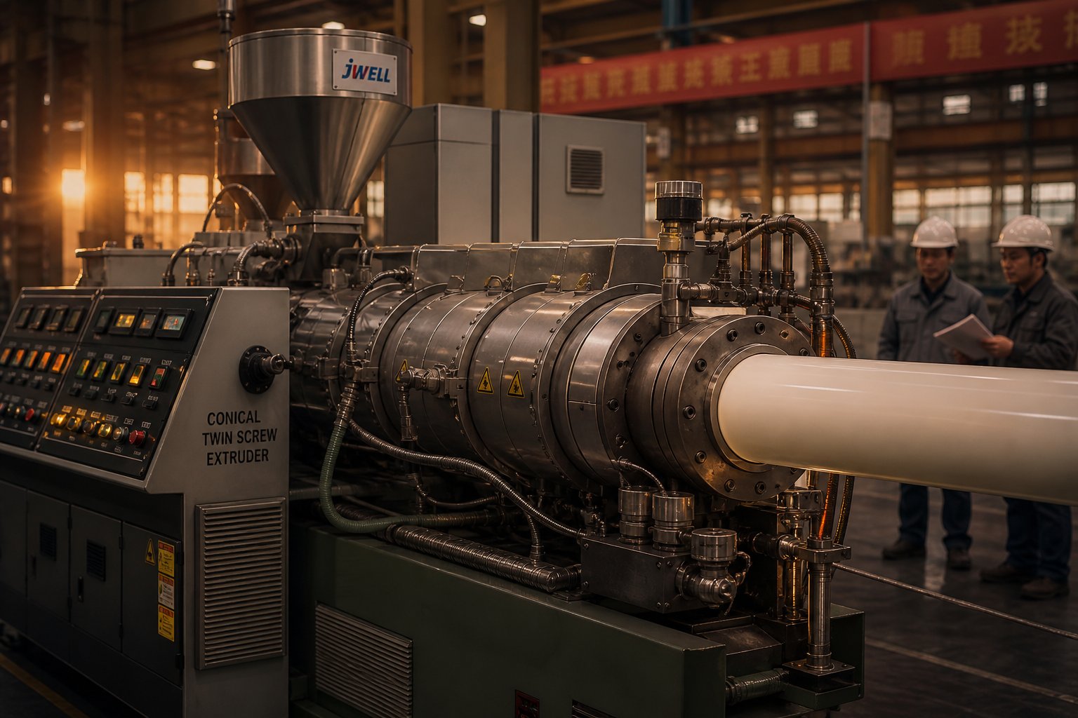
Gearbox torque, taper geometry, and counter-rotating conveying are engineering principles. But principles only matter when they translate into better products coming off the end of the line. So where does the conical twin screw extruder design actually prove its value on the factory floor? The answer centers on a small group of demanding applications where gentle processing, consistent melt quality, and thermal precision are non-negotiable.
PVC Processing and Thermal Stability
PVC is unlike most thermoplastics. It has a narrow processing window, typically between 160 and 200 degrees Celsius, and it begins to release hydrochloric acid and discolor if melt temperature or residence time creeps even slightly beyond safe limits. Excessive shear accelerates this degradation dramatically. Every unnecessary degree of frictional heating pushes the polymer closer to chemical breakdown, and once degradation starts, it catalyzes itself, making recovery impossible.
This is precisely why the conical twin screw extruder for PVC has remained the industry standard for decades. The low screw speeds, typically 15 to 50 rpm, combined with the natural compression of the taper, mean the material plasticizes gradually rather than being forced through high-intensity kneading zones. Shear energy distributes evenly along the entire barrel length instead of spiking at localized mixing elements. The result? Melt temperatures stay well within PVC's safe window, thermal stabilizers work as intended, and the finished product retains its mechanical strength, color consistency, and surface finish.
Counter-rotating intermeshing further protects the material. The closed C-shaped chambers deliver positive displacement conveying with minimal backflow, which keeps residence time predictable. Every particle of PVC compound spends roughly the same amount of time in the barrel, eliminating the hot spots and stagnant zones that cause premature degradation in less controlled conveying systems.
WPC and Profile Extrusion Applications
Wood-plastic composites present a different but equally demanding challenge. WPC formulations combine thermoplastic matrices, usually polyethylene or PVC, with high loadings of wood flour or natural fiber, sometimes reaching up to 70% fiber content. These fibers are heat-sensitive, moisture-containing, and abrasive. Process them too aggressively, and the wood fibers break down, releasing volatiles that cause surface defects and weakening the composite structure.
Conical twin screw extruders handle WPC exceptionally well. The large feed-end diameter provides generous channel volume that accepts fluffy, low-bulk-density wood flour blends without bridging or starve-feeding. As the taper compresses this loose mixture, the wood particles are progressively wetted out by the molten polymer, a process that demands time and gentle pressure rather than high shear intensity. Deep flight channels and tight intermesh clearances between the conical screws optimize material mixing while keeping shear forces low enough to prevent fiber degradation, exactly the combination needed for uniform fiber distribution without breakage.
The high-torque, low-speed operation that the conical gearbox enables is critical here. A twin screw compounding extruder designed for high-speed dispersive mixing would shred natural fibers and overheat the polymer matrix. A conical machine running at around 30 rpm delivers the sustained pushing force needed to move a viscous, heavily filled melt through complex profile dies, while keeping the composite intact.
Here is a breakdown of the primary application categories and why conical design characteristics align with each:
- PVC pipe extrusion. Smooth, progressive compression produces a homogeneous melt with minimal thermal history, yielding pipes with consistent wall thickness, high impact resistance, and reliable pressure ratings.
- PVC profile extrusion. Low-pulsation melt delivery from positive displacement conveying ensures tight dimensional tolerances on complex window frame, door, and trim profiles where surface finish quality is critical.
- PVC sheet and film production. Even melt temperature distribution across the die width prevents localized degradation streaks, delivering optically uniform sheet with consistent gauge.
- Wood-plastic composite (WPC) profiles. Gentle mixing at high torque achieves thorough fiber wetting without fiber breakage, producing structurally sound decking, fencing, and cladding with clean surface aesthetics.
- Calcium carbonate and mineral-filled PVC compounds. The natural compression accommodates high filler loadings while the low shear prevents excessive abrasive wear on screw and barrel surfaces, extending component life.
Matching Design Characteristics to End-Product Quality
What connects all of these applications? Each one demands a melt that is thermally uniform, free of degradation products, and delivered to the die at consistent pressure. You'll notice that these are not extreme throughput scenarios. They are precision scenarios, where product quality depends more on how gently and consistently material is plasticized than on how fast it moves through the barrel.
The conical architecture delivers this precision through its integrated design characteristics: geometric compression that avoids shear spikes, counter-rotating positive displacement that controls residence time, and a high-torque gearbox that maintains stable screw speed under heavy load. When these elements work together on a well-maintained machine, twin screw extruder manufacturers consistently report lower scrap rates, fewer color variations between production runs, and reduced stabilizer consumption compared to alternative extruder configurations processing the same PVC formulations.
For processors seeking custom or replacement conical twin screw barrels optimized for these applications, suppliers like NANHAIYA focus specifically on maintaining consistent plasticizing performance across PVC and WPC extrusion lines. Their emphasis on matched screw-and-barrel geometry ensures that replacement components preserve the designed compression ratio and processing window rather than introducing variables that compromise product quality.
These strengths, however, do not make the conical design a universal solution. Every specialized architecture carries inherent trade-offs, and understanding where this design reaches its limits is just as important as knowing where it excels.
Design Limitations and When Not to Use Conical Extruders
Every engineering advantage has a boundary. The same tapered geometry that gives conical screw extruders their gentle compression, high torque density, and compact footprint also imposes constraints that no amount of metallurgy or process optimization can overcome. Ignoring these limits leads to poor equipment selection, frustrated operators, and underperforming production lines. So where exactly does this design hit its ceiling?
Throughput and Scalability Constraints
The fixed taper geometry places a hard cap on how much material a conical machine can push through per hour. Increasing output on a parallel twin screw extruder is relatively straightforward: extend the barrel length, stretch the screw pitches, or increase the L/D ratio. Parallel designs can be extended in length more easily to boost throughput because the uniform barrel diameter allows additional modular sections to be bolted on without altering the compression profile.
A conical barrel does not offer that flexibility. The taper angle, large-end diameter, and small-end diameter are all interdependent. You cannot simply add barrel length without either changing the taper angle, which alters the compression ratio and processing behavior, or increasing the large-end diameter, which demands an entirely new gearbox and drive system. In practice, this means scaling up a conical extruder often requires replacing the entire machine rather than modifying the existing one.
Most conical twinscrew extruders used for rigid PVC operate within a throughput band of roughly 200 to 800 kg/h, depending on screw diameter. That range covers the vast majority of PVC pipe and profile production needs. But for high-volume compounding operations where throughput targets exceed several tonnes per hour, the conical architecture simply cannot compete with large parallel co-rotating machines capable of pushing beyond 20,000 kg/h.
Fixed Geometry vs Modular Flexibility
Imagine you run a facility that processes rigid PVC profiles one month, a glass-fiber-reinforced nylon the next, and a color masterbatch the week after. Could you do that on a single conical extruder? Practically speaking, no.
The tapered screws in a conical machine are typically machined as one-piece constructions. The barrel is a single converging unit. There are no interchangeable kneading blocks, no swappable mixing elements, and no option to rearrange the screw profile for a different processing task. The compression ratio, flight depth progression, and mixing characteristics are all locked in at the time of manufacture. A conical design offers more limited screw design freedom compared to parallel systems where segmented elements slide onto splined shafts and can be reconfigured in under an hour.
This rigidity is perfectly acceptable, even advantageous, for dedicated production lines running a single material family around the clock. A PVC pipe plant that extrudes the same formulation for years benefits from a screw geometry optimized specifically for that compound. But the moment a processor needs to switch between chemically different polymers or vary the mixing intensity for different additive packages, the conical extruder becomes a bottleneck rather than an asset.
Venting flexibility is another casualty of fixed geometry. Parallel extruders allow vacuum vent ports, side feeders, and liquid injection ports to be positioned at various barrel sections. Conical barrels offer limited venting flexibility, which can narrow the processing window, particularly when achieving optimal gelation while extracting entrapped air simultaneously.
When to Choose a Different Extruder Type
Transparency about limitations helps you avoid costly mismatches. Here are the specific scenarios where a conical vs parallel twin screw extruder comparison tips decisively away from the conical design:
- High-volume compounding operations. If your target throughput exceeds 1,000 kg/h for compounding engineering plastics, masterbatch, or filled concentrates, a parallel co-rotating extruder provides the scalability, modular screw configurations, and high-speed intensive mixing the application demands.
- Multi-material, multi-product facilities. Plants that frequently switch between different polymer families, filler types, or additive systems need modular screw and barrel flexibility. The fixed geometry of a conical machine makes rapid changeovers impractical.
- Reactive extrusion and devolatilization. Processes that require long residence times, multiple vent ports, and precisely staged mixing zones are better served by parallel twin screw extruders with configurable L/D ratios up to 52:1 or higher.
- Dispersive mixing-intensive applications. When you need to break apart filler agglomerates at the sub-micron level, such as in carbon black dispersion or nanocomposite compounding, the gentle distributive mixing of a counter-rotating conical machine is insufficient. High-shear co-rotating kneading blocks are essential.
- Research and development. Laboratory and pilot-scale work demands the ability to experiment with different screw configurations quickly. Segmented parallel extruders are purpose-built for this kind of iterative process development.
None of these limitations diminish the conical design's excellence within its intended domain. They simply define its boundaries. A conical twin screw extruder is a specialist, not a generalist, and the most successful processors treat it accordingly: deploy it where its strengths align with the application, and reach for a different architecture when the processing requirements fall outside its design envelope.
Recognizing these boundaries also matters for another practical reason. When a conical machine operates within its designed range, performance depends heavily on maintaining the precise clearances and compression profile the taper was built to deliver. Over thousands of operating hours, wear changes those clearances, and the consequences follow a pattern unique to tapered geometry.
Wear Patterns and Maintenance for Conical Twin Screw Barrels
A conical extruder's processing performance is defined by geometry, but geometry does not stay static. Every hour of operation chips away at the precision surfaces that make the taper work. Unlike a parallel machine, where wear progresses relatively uniformly along a constant-diameter bore, a converging barrel and tapered screws wear differently at each point along their length. Understanding these non-uniform wear patterns is the difference between catching a problem early and discovering it in rejected product.
Non-Uniform Wear Along the Taper
Why would a single pair of screws wear unevenly from one end to the other? Because the physics change along the taper. At the feed end, the large screw diameter means higher circumferential speed at the flight tips, even though the screw rpm is the same everywhere. That increased tip velocity creates more abrasive contact between the flight crests and the barrel wall, especially when processing formulations loaded with calcium carbonate, titanium dioxide, or other mineral fillers. The feed zone also handles material in its least-compacted, most granular state, where hard particles have the freedom to tumble and score surfaces.
Move toward the discharge end, and the scenario shifts. The smaller screw diameter reduces tip speed, lowering abrasive intensity. However, the material here is a fully compacted, high-viscosity melt under significant pressure. Adhesive wear becomes the dominant mechanism: molten polymer generates friction against metal surfaces under load, gradually removing material from flight flanks and barrel linings through a combination of surface shear and chemical interaction. Corrosive wear also concentrates here for PVC processing, because hydrochloric acid traces released during plasticizing attack exposed metal surfaces in the high-pressure, high-temperature metering zone.
The practical result is that twin-screw extruders running conical screws develop distinct wear signatures at different barrel positions:
- Feed zone (large diameter): Predominantly abrasive wear on flight crests and barrel bore from hard filler particles; scratching and scoring patterns visible on disassembled components.
- Compression zone (mid-taper): Combined abrasive and adhesive wear as material transitions from granular to molten state; the most complex wear region because both mechanisms overlap.
- Metering zone (small diameter): Primarily adhesive and corrosive wear from high-pressure melt contact; surface pitting and chemical erosion rather than mechanical scoring.
This variation matters because it means you cannot assess the condition of a conical screw-and-barrel set by measuring wear at a single point. A barrel that looks fine at the feed end may be critically worn at the metering zone, or vice versa. Inspection must cover the full taper length, with measurements taken at multiple stations along the bore.
Critical Clearance and Processing Quality
In any twin screw extruder, the flight clearance, the gap between the screw flight tip and the barrel wall, is a tightly controlled dimension. For a new double screw extruder machine, this clearance typically follows the industry guideline of the nominal screw diameter divided by 1,000 per side. As Plastics Technology notes, even a 100-mm screw starts life with a flight clearance of roughly 0.005 inches per side. That tiny gap is what allows the screw flights to scrape the barrel wall effectively, renewing the thin melt film that transfers heat from the barrel heaters into the polymer.
In a conical barrel, this clearance is not a single number. It varies along the taper because the screw diameter changes continuously. At the large feed end, the designed clearance corresponds to the large-end diameter; at the small discharge end, it corresponds to the smaller diameter. Wear at any point along the taper increases the local clearance, and in a converging geometry, even small clearance changes have outsized consequences.
Here is why. The taper creates a progressive compression profile, and that profile depends on the ratio of channel volume at the feed end to channel volume at the discharge end. When wear increases the clearance at the metering zone, melt can leak backward over the flight tips more easily, reducing the effective compression ratio. Material that should be pushed forward under high pressure instead slips back, forming a recirculation loop that wastes energy and generates excess shear heat in exactly the zone where PVC is most vulnerable to degradation.
Conversely, if the feed zone wears faster, intake efficiency drops. The wider clearance at the feed end means the screws can no longer seal incoming powder in those closed C-shaped chambers as effectively. Conveying becomes partially drag-dependent rather than purely positive-displacement, leading to output fluctuations that show up as inconsistent wall thickness in pipes or dimensional drift in profiles.
The key maintenance indicators that signal clearance-related wear problems include:
- Increased energy consumption. The motor must work harder to maintain the same output because material leakage over worn flights wastes pumping effort. A gradual upward trend in specific energy consumption, kilowatt-hours per kilogram of output, is often the earliest detectable sign.
- Inconsistent melt temperature. Worn clearances alter the balance between conductive heating from the barrel wall and frictional heating from screw rotation. Operators notice wider temperature swings across the die face or between production cycles.
- Reduced output rate at constant screw speed. If the screw speed stays the same but throughput drops, material is leaking backward over the flights rather than moving forward. This is the classic symptom of excessive flight clearance, and industry data shows that the rate reduction can reach 13% or more before the operator compensates by increasing screw speed, which only accelerates further wear.
- Visible wear marks on screw flights and barrel bore. Scoring, grooves, and polished patches on disassembled components confirm where metal-to-metal contact or abrasive particle damage has been most severe.
- Higher discharge temperatures. As the heat-transfer coefficient drops because the melt film on the barrel wall thickens with increased clearance, the extruder compensates with more shear heating, pushing discharge temperatures above the safe processing window.
When and How to Replace Conical Screw Barrels
Timing a conical twin screw barrel replacement is as much an economic decision as a technical one. Some processors follow a simple rule: replace when flight clearance reaches four times its original specification. Others wait until the hard-facing alloy on the flight crests is completely worn through. The best approach, as extrusion troubleshooting experts consistently recommend, is to replace based on process economics. When the cost of reduced output, elevated scrap rates, and increased energy consumption exceeds the cost of new components, the replacement pays for itself.
What makes conical barrel replacement different from parallel barrel replacement is the matched geometry requirement. In a parallel machine, you might replace just the screw and continue using the original barrel if its bore is still within tolerance, or vice versa. In a conical system, the taper angle, the compression ratio, and the clearance profile are all interdependent. Replacing one screw without addressing barrel wear, or installing a new barrel with worn screws, introduces a mismatch between the two taper surfaces. That mismatch changes the designed compression profile, alters the pressure generation curve, and can create localized high-wear zones where the new component contacts the worn one unevenly.
For this reason, best practice calls for matched screw-and-barrel replacement sets. When sourcing replacements, look for suppliers that manufacture the screw pair and barrel as a coordinated unit, machined to the same taper angle and finish tolerances. Suppliers like NANHAIYA specialize in custom and replacement conical twin screw barrels designed to restore the original compression ratio and plasticizing performance, with a focus on supporting PVC and WPC extrusion lines where clearance precision directly governs product quality.
A few practical guidelines help maximize the return on replacement components:
- Measure before ordering. Record the existing taper angle, large-end diameter, small-end diameter, and wear dimensions at multiple stations along the bore. These measurements ensure the replacement set matches the original machine specifications rather than introducing geometry variations.
- Track wear progression. Keep a log of clearance measurements taken during scheduled maintenance intervals. Plotting this data over time reveals the wear rate and helps predict when the next replacement will be needed, allowing procurement lead times to align with scheduled downtime.
- Consider metallurgy upgrades. If your formulation has become more abrasive, for example, due to higher calcium carbonate loading, the replacement cycle is an opportunity to specify bimetallic barrel linings or upgraded flight-tip hard-facing alloys that extend service life in the specific wear zones your process stresses most.
- Never refurbish indefinitely. Industry guidance suggests a screw should not be refurbished more than three times. Each welding cycle to rebuild worn flight tips degrades the base metal, increasing the risk of delamination between the hard-facing layer and the screw body.
Wear is inevitable, but it does not have to be unpredictable. A conical twin screw extruder that is monitored, measured, and maintained on a data-driven schedule will deliver consistent plasticizing performance for years between component changes. The processors who track their clearance trends and plan replacements proactively are the ones who avoid the cascade of quality problems, energy waste, and emergency downtime that follow when worn components are left in service too long.
Component longevity, however, is not just about monitoring wear after it happens. Modern metallurgy, surface treatments, and computational design tools are actively pushing the boundaries of how long conical screws and barrels can resist degradation in the first place.
Modern Design Evolution in Conical Twin Screw Technology
Wear resistance is reactive. You measure degradation, track trends, and replace components before quality suffers. But what if the components themselves could resist degradation far longer than traditional steel allows? What if the taper angle could be fine-tuned through simulation before a single gram of metal is cut? Modern engineering is answering both questions, pushing the conical twin screw extruder design well beyond its mid-20th-century origins while preserving the fundamental geometry that makes it work.
Advanced Metallurgy and Surface Treatments
The biggest leap in component longevity has come from bimetallic construction. A bimetallic screw barrel bonds a wear-resistant alloy liner, typically 1 to 2 mm thick and rich in chromium, nickel, or tungsten carbides, to a structural steel core through centrifugal casting or thermal cladding. The inner alloy handles the abrasion and corrosion, while the outer steel provides toughness and mechanical integrity.
The performance gains are substantial. Depending on the alloy grade, bimetallic barrels deliver three to seven times the abrasion resistance of standard nitrided barrels. For conical twin screws processing heavily filled PVC or WPC formulations, where calcium carbonate and wood fiber particles constantly grind against metal surfaces, that multiplier translates directly into years of extended service life and fewer unplanned shutdowns.
Corrosion resistance matters just as much. PVC releases trace amounts of hydrochloric acid during plasticizing, and those traces attack exposed steel surfaces relentlessly over time. Nickel-alloy liners and chromium-nickel overlays combat this chemical wear, preserving the smooth bore finish that maintains consistent melt flow and prevents material stagnation. Because the bimetallic liner resists dimensional loss, the critical flight clearance along the taper stays stable far longer, sustaining the designed compression ratio and plasticizing consistency that conical geometry depends on.
On the screw side, hard-facing alloys applied to flight crests, stellite, colmonoy, and proprietary carbide blends, protect the most vulnerable wear surfaces. Modern plasma-transferred-arc welding and laser cladding techniques deposit these alloys with tighter thickness control and better metallurgical bonding than earlier methods, reducing the risk of delamination that has historically limited how many times a screw can be refurbished.
Computational Optimization of Taper Angles
For decades, taper angle selection was guided by experience and trial-and-error. A designer would choose a taper based on successful previous builds, test it with a target formulation, and adjust if necessary. That approach worked, but it left performance on the table because the interplay between taper angle, compression ratio, melt temperature, throughput, and mixing quality involves too many variables for intuition alone to optimize.
Computational simulation has changed this fundamentally. Researchers at Warsaw University of Technology developed global models and genetic-algorithm-based optimization software specifically for counter-rotating twin screw extrusion. Their TSEM simulation platform predicts pressure profiles, temperature distributions, solid-bed melting progression, and fill-factor behavior along the full screw length, then uses multi-objective optimization to find operating parameters that maximize throughput while minimizing melt temperature and melting length simultaneously.
What does this mean in practical terms? Imagine being able to test dozens of taper angle variations, flight depth progressions, and operating conditions digitally before committing to a physical screw build. Computational tools let manufacturers fine-tune the taper geometry so that compression, mixing, and pressure generation are balanced precisely for a specific polymer and die configuration. The result is extruder twin screw designs that extract more performance from the same fundamental conical architecture, not by changing the concept but by refining its execution with data.
Enhanced cooling and temperature control systems complement these simulation-driven designs. Modern conical barrels feature independently controlled heating and cooling zones with tighter spacing along the converging bore. Precision thermocouples and zone-specific cartridge heaters or cast-in heating elements provide thermal management accurate to within a few degrees, allowing operators to shape the melt temperature profile deliberately rather than accepting whatever the process delivers. For PVC, where even a five-degree overshoot can trigger degradation, this level of thermal precision is transformative.
Manufacturing tolerances have tightened in parallel. CNC grinding and honing of barrel bores, combined with multi-axis CNC machining of screw flights, produce components with surface finishes and dimensional accuracy that were unachievable a generation ago. Tighter tolerances on flight clearance at every point along the taper mean more uniform compression, less leakage flow, and more predictable output from the first kilogram of production onward.
Digital Monitoring and Future Design Trends
The newest evolution does not involve the twin screws themselves but the intelligence wrapped around them. Integrated digital monitoring systems now track the real-time health of screw and barrel components during operation, turning reactive maintenance into predictive maintenance.
The concept is straightforward. Continuous sensor data, barrel zone temperatures, melt pressure, motor amperage, screw speed, and output rate, establishes a baseline fingerprint of a healthy extruder. As wear progresses, the fingerprint shifts: specific energy consumption rises, output per rpm declines, and melt temperature deviates from barrel setpoints. Monitoring platforms detect these trends weeks or months before they cause product quality failures, giving maintenance teams time to schedule component replacement during planned downtime rather than scrambling after a breakdown.
Key indicators that digital systems track for conical machines include:
- Output-to-screw-speed ratio. A declining ratio signals increasing backflow over worn flight tips, the earliest measurable sign of clearance degradation.
- Specific energy consumption (kWh/kg). Changes reflect shifts in pumping efficiency, melting behavior, and frictional heating as component geometry drifts from specification.
- Melt temperature deviation from barrel setpoints. A growing gap indicates that shear heating is replacing conductive heating, a hallmark of worn flights losing effective barrel-wall contact.
- Motor amperage trends at constant rpm. Increasing load at the same speed points to changing melt viscosity from degradation or altered compression dynamics from wear.
These data streams, correlated over time, build a wear curve specific to each machine, material, and operating condition. After two or three replacement cycles with full data history, processors can predict the next replacement window within weeks, transforming a high-cost emergency event into a routine, budgeted maintenance task.
Looking further ahead, the convergence of simulation-optimized geometry, advanced bimetallic metallurgy, and real-time digital monitoring is creating a new generation of conical extruders that are smarter, more durable, and more precisely tuned than anything the industry has seen. The fundamental conical twin screw extruder design remains unchanged at its core, two tapered screws in a converging barrel, because the physics that make it effective have not changed. What has changed is how deeply engineers can now understand, optimize, and sustain that design across its entire operating life.
That deeper understanding is exactly what this article has aimed to provide. From the taper geometry that creates natural compression, through the counter-rotating mechanism that delivers positive displacement conveying, to the gearbox architecture that enables high-torque operation, and finally to the wear patterns and metallurgical advances that determine long-term reliability, every aspect of conical twin screw extruder design follows logically from first principles. Processors who grasp these principles do not just operate their equipment. They make sharper decisions about equipment selection, process optimization, maintenance timing, and component sourcing, decisions that compound into measurable gains in product quality, uptime, and operating cost over the life of every machine on the floor.
Frequently Asked Questions About Conical Twin Screw Extruder Design
1. What is the main difference between a conical and parallel twin screw extruder?
The core difference lies in screw geometry and how each machine achieves compression. A conical twin screw extruder uses tapered screws that decrease in diameter from the feed end to the discharge end, housed in a converging barrel. This taper creates natural, progressive compression along the entire barrel length without relying on aggressive mixing elements. A parallel twin screw extruder maintains a uniform screw diameter and depends on configurable screw elements like kneading blocks and reverse-pitch segments to build localized compression zones. Conical designs typically counter-rotate at low speeds (15-50 rpm) for gentle, positive-displacement conveying, while parallel co-rotating designs run at high speeds (200-1,200 rpm) with modular flexibility suited to compounding diverse materials.
2. Why are conical twin screw extruders preferred for PVC processing?
PVC has an exceptionally narrow processing window, roughly 160 to 200 degrees Celsius, and degrades rapidly when exposed to excessive shear heat or prolonged residence time. Conical twin screw extruders address these sensitivities through three integrated mechanisms. First, the tapered barrel distributes compression evenly along the screw length, avoiding the concentrated shear spikes that kneading blocks create in parallel machines. Second, counter-rotating intermeshing screws form sealed C-shaped chambers that deliver positive displacement conveying, ensuring every particle spends a uniform, predictable time in the barrel. Third, the large feed-end diameter supports a high-torque gearbox that maintains stable output at very low screw speeds, minimizing frictional heat generation. Together, these characteristics keep melt temperatures safely below PVC's degradation threshold while achieving thorough plasticizing. Suppliers like NANHAIYA (https://www.nhyscrews.com/products/conical-twin-screw-barrel) offer custom conical twin screw barrels specifically optimized for maintaining consistent plasticizing performance in PVC extrusion lines.
3. How does the gearbox design differ in a conical twin screw extruder?
Unlike a parallel twin screw extruder where both output shafts run side by side at a fixed center distance, a conical extruder gearbox must accommodate two output shafts that converge at the taper angle of the barrel. This requires specialized angular gear sets, typically bevel gears, to split motor torque into two converging paths. The key advantage is that the wider spacing between screw axes at the feed end provides substantially more room for larger radial bearings, bigger thrust bearings, and greater shaft diameters. This translates into significantly higher torque capacity per unit of output-end cross-section compared to parallel designs of similar discharge diameter. The wide bearing span also reduces contact stresses, extending service intervals and improving mechanical stability throughout the machine's operating life.
4. What are the limitations of conical twin screw extruders?
Conical twin screw extruders are specialists, not generalists, and their fixed taper geometry introduces several constraints. Throughput scalability is limited because extending barrel length changes the taper angle and compression ratio, often requiring a completely new machine rather than simple modifications. Most conical machines operate within 200 to 800 kg/h, far below the 20,000+ kg/h achievable with large parallel co-rotating extruders. The one-piece screw and barrel construction offers no modularity, meaning you cannot swap kneading blocks or rearrange mixing elements for different formulations. Venting flexibility is also restricted, limiting options for vacuum ports or side feeders. These constraints make conical designs unsuitable for high-volume compounding, multi-material facilities, reactive extrusion, or R&D applications that demand frequent screw reconfiguration.
5. How do you know when conical twin screw barrels need replacement?
Wear in conical barrels progresses non-uniformly along the taper, so monitoring must cover multiple measurement stations along the full bore length. Key indicators that signal replacement is approaching include a gradual rise in specific energy consumption (kWh/kg), declining output rate at constant screw speed, inconsistent melt temperatures across the die face, and visible scoring or pitting on disassembled components. A common benchmark is replacing components when flight clearance reaches four times its original specification. Critically, conical screw and barrel sets should always be replaced as matched pairs because the interdependent taper angle and compression ratio require coordinated geometry. Mismatched components alter the designed compression profile and create localized high-wear zones. Specialized suppliers such as NANHAIYA (https://www.nhyscrews.com/products/conical-twin-screw-barrel) manufacture matched replacement sets to restore original compression ratios and plasticizing performance for PVC and WPC extrusion lines.
Written by
Nanhaiya Technical Team
Zhoushan Nanhaiya Plastic Machinery Co., Ltd.
The Nanhaiya technical team supports screw and barrel manufacturing projects through application review, technical communication, custom manufacturing coordination, and production and quality control.
Discuss Your Application
Related Articles
More insights on screw barrel technology and plastics processing.

Extruder Machine Decoded: From Raw Pellet To Finished Product
Oct 6, 2026
Learn how an extruder machine works, compare single-screw vs. twin-screw types, and get expert guidance on specs, troubleshooting, and selection.
Read Article
PE Pipe Making Machine Decoded: From Raw Resin to Flawless Pipe
Oct 4, 2026
Learn how a PE pipe making machine works, from resin to finished pipe. Covers components, material grades, automation, troubleshooting, and buyer selection tips.
Read Article
PVC Profile Making Machine Decoded: From Raw Resin To Profit
Oct 3, 2026
Learn how a PVC profile making machine works — extrusion process steps, key technical parameters, die design, calibration methods, maintenance, and total cost of ownership.
Read ArticleLooking for something else?
Search by material, symptom or product and jump straight to the relevant page.
These are navigation suggestions based on keyword matching — not a quotation, not a delivery commitment, and not a substitute for engineering review. Final specification is confirmed by our engineers against your drawings and processed material.
Need help with screw barrel selection?
Share your machine model, processed material and application. Our team can help with pricing and technical support.