

What Is a Conical Twin Screw Extruder and Who Needs One
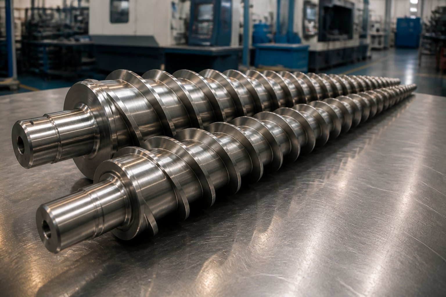
Imagine two screws shaped like elongated cones, wide at one end and tapering down to a narrow tip at the other. Place them side by side inside a barrel that mirrors that exact taper, and you have the defining architecture of a conical twin screw extruder. It sounds simple, but that geometry is the reason this machine dominates an entire segment of the plastics industry.
What Defines a Conical Twin Screw Extruder
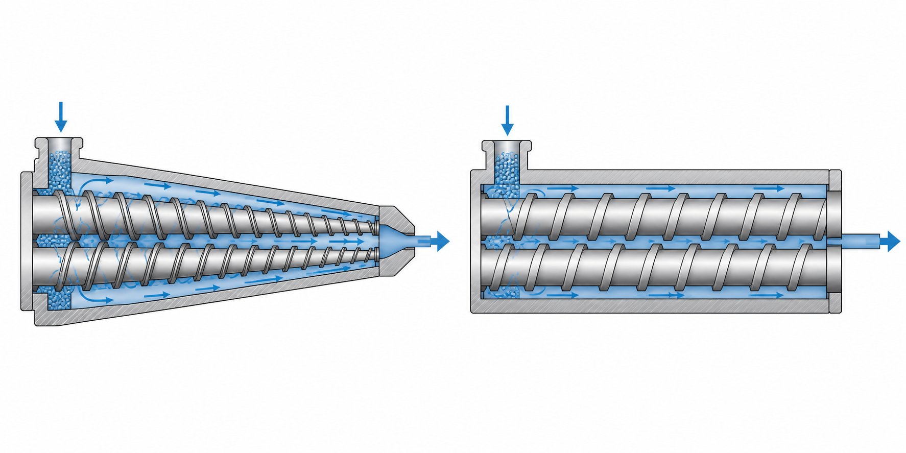
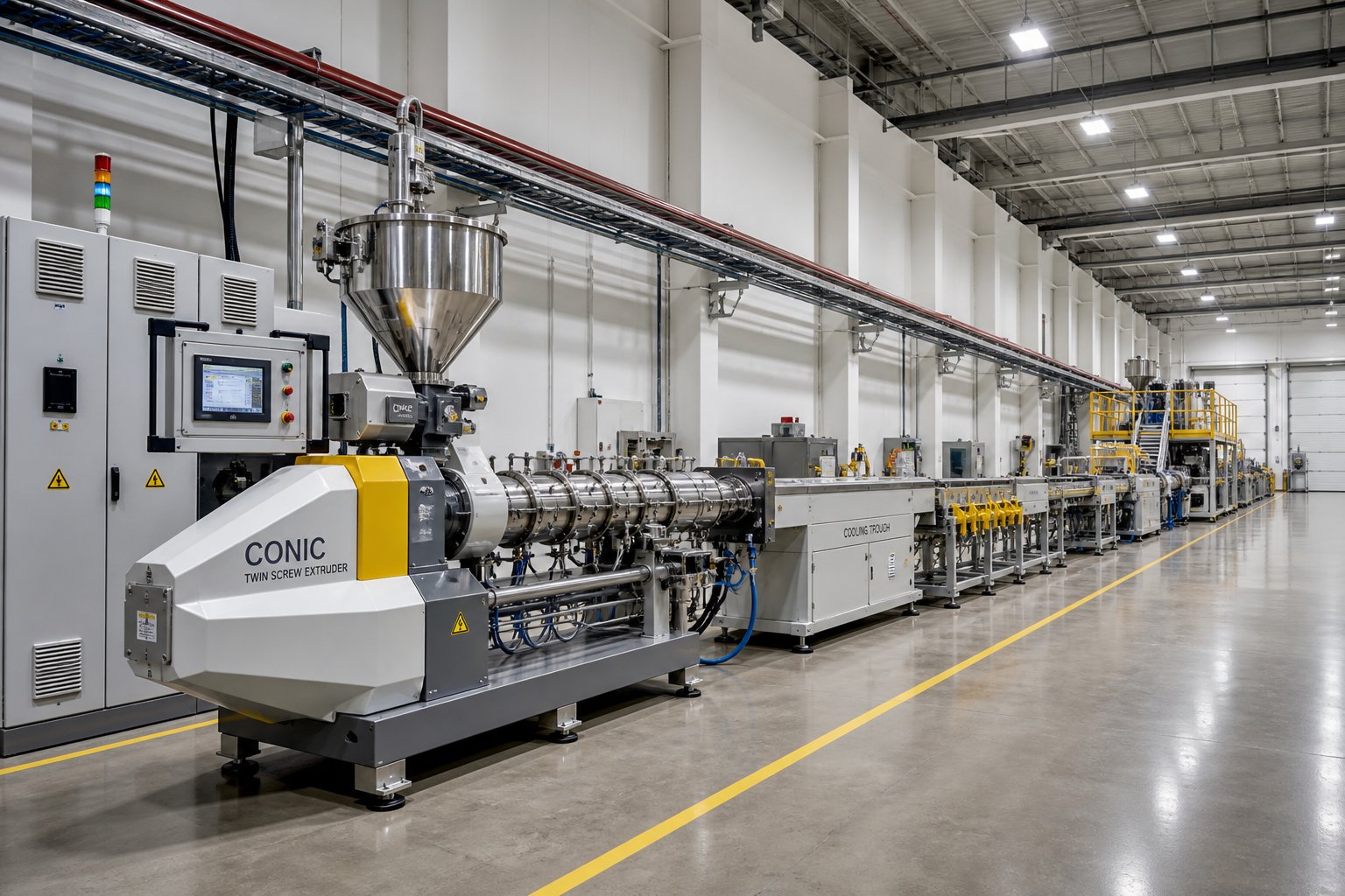
A conical twin screw extruder is a plastics processing machine built around two intermeshing, tapered screws housed within a matching conical barrel. The screws feature a larger diameter at the feed end, where raw material enters, and a progressively smaller diameter at the discharge end, where molten material exits toward the die. This tapered design sets it apart from the more familiar parallel twin screw extruder, where both screws maintain a uniform diameter from inlet to outlet.
A conical twin screw extruder uses two tapered, counter-rotating screws - wider at the feed end and narrower at the discharge end - housed in a matching conical barrel to gently compress, plasticize, and convey heat-sensitive materials like PVC with minimal thermal degradation.
Why does that taper matter so much? The gradually decreasing channel volume creates a natural compression effect as material travels along the screws. There is no need for aggressive screw geometry or extreme barrel pressures to densify the feedstock. The conical screw does it progressively, almost passively, through its shape alone. The result is lower shear stress, less frictional heat, and far gentler processing - a critical advantage when the material you are working with degrades easily under heat.
Most conical designs operate in a counter-rotating configuration, meaning the two screws turn in opposite directions. This creates a calendering-like action between the screws that positively conveys material forward with minimal backflow. You will rarely encounter co-rotating conical setups because the counter-rotating arrangement already delivers exactly what heat-sensitive polymers demand: consistent, low-shear forward movement.
Who Uses Conical Twin Screw Extruders and Why
If your facility processes PVC in any form, there is a strong chance a conical twin-screw extruder is either already on your floor or should be. These machines have become the workhorse for several specific sectors:
- PVC pipe manufacturers - producing water supply, drainage, and electrical conduit pipes from rigid PVC dry blends that require precise thermal control.
- Window and door profile extruders - creating complex cross-section profiles where uniform plasticizing directly determines dimensional accuracy and surface finish.
- Wood-plastic composite (WPC) producers - processing blends of wood fiber and thermoplastic that need gentle handling to preserve fiber integrity while achieving thorough encapsulation.
- PVC sheet and film producers - forming flat products that demand consistent melt delivery and minimal thermal history variation.
Production engineers value the machine for its process stability and forgiving nature with heat-sensitive formulations. Plant managers appreciate its compact footprint and energy efficiency compared to equivalent-output parallel systems. And if you are new to extrusion technology, the conical twin screw extruder is an excellent starting point to understand because its design logic is intuitive - the taper tells you exactly what the machine is doing to the material at every stage.
The real question is not simply what this machine is, but why its tapered geometry solves problems that other extruder configurations struggle with - a question rooted in engineering fundamentals that deserve a closer look.
The Engineering Rationale Behind the Conical Screw Design
A taper is never arbitrary in machine design. Engineers do not shape twin screws into cones for aesthetics - they do it to solve three persistent problems that plague plastics processing with powdery, heat-sensitive feedstocks. Each advantage traces directly back to the geometry itself, and understanding these principles reveals why the conical configuration has remained the preferred architecture for PVC extrusion for decades.
Why Tapered Screws Solve the Bulk Density Problem
Picture a bag of PVC dry blend sitting next to a bag of PVC pellets. The pellets are dense, compact, and flow easily. The dry blend? It is a fluffy, powdery mixture with a bulk density often below 0.6 g/cm³ - sometimes as low as 0.5 g/cm³. Getting that low-density powder into an extruder efficiently is a real challenge. A parallel twin screw extruder, with its uniform-diameter screws, offers the same channel volume at the feed opening as it does further downstream. That limits how much of a bulky, airy powder you can pull in per screw revolution.
The conical design flips this constraint on its head. Because the feed end of the twin screws features a significantly larger diameter than the discharge end, the intake zone has a much wider, deeper channel. Think of it as a wide-mouth funnel versus a narrow straw - the funnel naturally accepts more volume. This large feeding area allows the screws to grab and pull in low-bulk-density powders at a rate that matches the machine's downstream processing capacity. You avoid starving the extruder, and you eliminate the need for force-feeding systems that add complexity and cost.
As the material moves along the tapered channel, the progressively shrinking cross-section compresses it naturally. There is no abrupt transition, no sudden spike in pressure. The powder densifies gradually, which is exactly what heat-sensitive PVC formulations need. Sudden compression generates frictional heat and localized shear spikes - both of which can trigger premature degradation in a polymer with a notoriously narrow processing window of roughly 180°C to 200°C for final process temperatures.
There is also a torque advantage baked into the geometry. The larger root diameter at the feed end means the screw shaft is thicker and stronger precisely where the mechanical load is highest - at the point where cold, unplasticized powder resists being moved forward. This allows the drive system to transmit higher torque without risking shaft deflection or fatigue failure. In a parallel design, achieving equivalent torque capacity requires either increasing overall screw diameter (which increases machine size and cost) or accepting a lower torque ceiling.
These three advantages work together as an integrated system:
- Improved feeding efficiency - The wide-diameter intake zone accepts high volumes of low-bulk-density powders without force-feeding, maximizing material intake per revolution.
- Natural, progressive compression - The taper compresses material gradually along the screw length, avoiding sudden pressure spikes that generate excess shear heat and degrade sensitive polymers.
- Superior torque transmission - The larger root diameter at the feed end provides a stronger mechanical foundation for torque transfer, enabling reliable processing of resistant, unplasticized feedstocks.
Counter-Rotation in Conical Designs Explained
When discussing co rotating and counter rotating twin screw extruder configurations, the distinction is straightforward but consequential. In a co rotating twin screw extruder, both screws spin in the same direction - either both clockwise or both counterclockwise. This creates an intermeshing zone where material is transferred from one screw to the other in a figure-eight path, generating high shear and intensive dispersive mixing. That is ideal for compounding engineering plastics, blending masterbatches, or incorporating difficult-to-disperse additives.
Counter-rotating designs work on a fundamentally different principle. The screws rotate in opposite directions, creating a calendering action at the nip point where the flights intermesh. Material is trapped in the closed C-shaped chambers formed between the screw flights and the barrel wall, then positively conveyed forward like a series of sealed pockets moving along a conveyor. Backflow is minimal. Shear is controlled and gentle.
Why does this matter for conical extruders specifically? PVC does not behave like polyethylene or polypropylene. It does not melt into a clean, free-flowing liquid. Instead, it undergoes a complex fusion process where powder grains gradually soften, compact, and fuse together. Excessive shear or overheating at any point during this process risks thermal degradation - releasing hydrochloric acid that corrodes equipment and ruins the product. The counter-rotating configuration's positive pumping action moves PVC through the barrel with a predictable, uniform residence time, ensuring every particle experiences the same thermal and mechanical history.
This is precisely why you will find counter-rotation in the overwhelming majority of conical twin screw extruders. Co-rotating designs excel where aggressive mixing is the priority, but for materials that punish you for being too aggressive, the gentle, positive-displacement conveying of counter-rotating conical twin screws is not just preferable - it is essential.
These engineering principles explain why the conical design exists. The next logical question is how it stacks up head-to-head against its parallel counterpart across the full range of performance criteria that matter on the production floor.
Conical vs Parallel Twin Screw Extruder Comparison
Every extrusion decision eventually comes down to trade-offs. The conical twin screw extruder and the parallel twin screw extruder are not competing solutions to the same problem - they are optimized answers to different sets of processing demands. Choosing between them requires a clear-eyed look at what each design genuinely does better and where it falls short.
Structural and Mechanical Differences
The most visible difference is the screw geometry itself. In a conical setup, two tapered screws sit at an angle to each other, converging toward the discharge end. The barrel mirrors this taper, creating a naturally narrowing processing channel. A parallel twin screw extruder, by contrast, features two screws of identical, constant diameter housed side by side in a straight cylindrical barrel at a fixed center distance. That single geometric distinction cascades into differences across nearly every performance metric.
Start with the drive system. Because conical screws have a larger root diameter at the feed end, they can accommodate bigger bearings and a more robust thrust assembly within a relatively compact gearbox. The tapered arrangement also means the screws physically diverge at the rear, leaving more room for the drive components. Parallel twin screw extruders achieve high torque through precision-engineered gearboxes with tightly spaced shafts, which becomes increasingly complex - and expensive - as screw diameters grow.
Barrel construction differs too. A conical barrel is essentially a single, tapered bore that must be machined to tight tolerances along its entire length. A parallel barrel, especially in co-rotating designs, often uses a modular segmented configuration. Individual barrel sections can be swapped, rearranged, or replaced with vented or side-fed segments. This modularity gives the parallel design a significant edge in process flexibility - you can reconfigure the barrel layout to suit different formulations without replacing the entire unit.
Screw length tells another part of the story. Parallel twin screw extruders typically offer longer L/D ratios, sometimes reaching 40:1 to 52:1 or higher. That extra length provides more processing zones for melting, mixing, venting, and homogenizing. Conical systems generally operate in the range of 22:1 to 26:1 L/D, which is shorter but sufficient for materials like PVC that benefit from reduced residence time and minimal thermal exposure.
Here is a side-by-side breakdown across the criteria that matter most on the production floor:
| Criteria | Conical Twin Screw Extruder | Parallel Twin Screw Extruder |
|---|---|---|
| Feeding Efficiency | Excellent for low-bulk-density powders; wide feed opening accepts fluffy dry blends without force-feeding | Better suited for pellets and pre-densified materials; may require crammers for low-density powders |
| Torque Capacity | High torque at the feed end due to larger root diameter; efficient load distribution across the taper | Requires more complex, precision gearbox design to achieve equivalent torque; scales well at larger sizes |
| Machine Footprint | Compact overall length; shorter barrel reduces floor space requirements | Longer barrel length increases footprint; modular design may require additional support infrastructure |
| Output Range | Typical range of roughly 50 to 1,000+ kg/h depending on screw size; best suited for moderate throughput applications | Scales to very high output rates, often exceeding several thousand kg/h; preferred for large-volume compounding |
| Best-Suited Materials | Rigid and flexible PVC dry blends, WPC, recycled PVC, and other heat-sensitive formulations | Engineering plastics (PA, PC, ABS), filled compounds, masterbatch, reactive extrusion feedstocks |
| Typical Applications | PVC pipe, window/door profiles, PVC sheet, WPC decking and cladding | Polymer compounding, color masterbatch, filled/reinforced plastics, devolatilization, reactive processing |
| Mixing Intensity | Gentle, low-shear positive conveying; limited dispersive mixing capability | High-shear, intensive dispersive and distributive mixing; configurable with kneading blocks |
| Energy Efficiency | Lower motor power needed for equivalent PVC output due to natural compression and shorter barrel; however, some comparisons show higher specific energy consumption per kg for certain products | Higher installed motor power but often lower specific energy at high throughput rates; efficiency improves with scale |
| Barrel Modularity | Fixed, one-piece tapered barrel; limited reconfiguration options | Segmented barrel sections allow flexible reconfiguration for different processes |
| Screw Wear and Replacement | Screws must be replaced as matched sets; tapered geometry may show faster localized wear in the compression zone | Individual screw elements can be replaced independently; wear is distributed more evenly across longer length |
Notice that neither design dominates across every category. The conical configuration earns its place through feeding efficiency, compact size, and gentle handling of thermally sensitive materials. The parallel design wins on versatility, scalability, and mixing performance. Each is the right tool in its own context.
When to Choose Conical Over Parallel
So how do you decide? The choice becomes clear when you map your production requirements against a few straightforward criteria.
If your primary feedstock is PVC dry blend - whether rigid or flexible - the conical design is almost certainly the better fit. Its wide intake zone efficiently handles the low-bulk-density powder that twin screw extrusion of PVC demands, and its gentle, counter-rotating action protects the polymer from the thermal degradation that plagues more aggressive processing methods. The same logic applies to WPC formulations, where wood fiber is easily damaged by excessive shear and requires careful moisture management rather than intensive mixing.
Consider a parallel twin screw extruder if your operation involves compounding engineering plastics, producing masterbatch with high pigment or filler loadings, or running reactive extrusion processes. These applications need the high shear, long residence time, and modular barrel flexibility that parallel designs - particularly co-rotating configurations - deliver. When you need to disperse nano-fillers into a nylon matrix or devolatilize a moisture-sensitive polycarbonate, no conical system can match what a parallel double screw extruder machine offers in mixing intensity and process control.
Output volume matters too. For PVC pipe and profile production at moderate throughput rates, conical twin screw extruders are the industry standard. But if your production goals push into multi-ton-per-hour compounding territory, the parallel architecture scales more effectively. Its uniform screw diameter allows proportional increases in channel volume without the geometric constraints that limit how large a conical design can practically grow.
Floor space is a practical factor that often gets overlooked. Conical systems pack their processing capability into a shorter overall machine length, which can be a deciding advantage in facilities where every square meter counts. Parallel machines, with their longer barrels and auxiliary equipment, demand more room.
Ultimately, the decision is not about which type of twin screw extruder is "better" in the abstract. It is about matching the machine's engineering strengths to your specific material, your output targets, and the quality standards your end products must meet. And for many processors, the most important variable in that equation is the material itself - a topic that deserves its own detailed examination.
Materials Best Suited for Conical Twin Screw Extrusion
Matching the right machine to the right material is where equipment selection either pays off or falls apart. A conical twin screw extruder is not a universal processor - it thrives with specific feedstocks that exploit its tapered geometry, low-shear conveying, and natural compression. Understanding which materials belong on this machine, and why, prevents costly mismatches and unlocks the performance the design was built to deliver.
Here is how the most common materials rank, from most ideal to acceptable, for processing on a plastic twin screw extruder with conical geometry:
- Rigid PVC (uPVC) - The definitive application. The conical design exists, in large part, because of this polymer.
- Flexible PVC (plasticized PVC) - Equally well-suited, with specific considerations around plasticizer handling.
- Wood-plastic composites (WPC) - A growing application where the conical geometry solves multiple challenges simultaneously.
- Recycled PVC - Inconsistent feedstock quality makes the forgiving conical feed zone a practical advantage.
- Other thermoplastics (PP, PE, ABS) - Processable but not where the conical design demonstrates its strongest advantages over alternatives.
PVC Processing on Conical Extruders
Rigid PVC sits at the top of the list for a reason that every PVC processor understands viscerally: this polymer punishes mistakes. Its processing window is notoriously narrow - melt temperatures typically need to stay between roughly 170°C and 200°C. Push beyond that range and the material begins releasing hydrochloric acid, discoloring the product, and corroding your equipment. A twin screw plastic extruder with conical, counter-rotating screws addresses this challenge directly. The low screw speeds - often just 20 to 45 rpm - minimize frictional heat generation. The progressive compression along the taper fuses PVC powder grains gradually rather than forcing them through abrupt high-shear zones. And the positive-displacement conveying action ensures a uniform residence time, so no particle lingers in a hot zone long enough to degrade.
Flexible PVC introduces a different wrinkle. Plasticizers like DOP or DINP are added to make the compound soft and pliable, but these additives are sensitive to excessive shear and heat. When a screw plastic extruder subjects plasticized PVC to aggressive mechanical action, plasticizer molecules can degrade or volatilize, leading to surface bloom, odor problems, and reduced flexibility in the finished product. The conical design's gentle calendering action between counter-rotating screws keeps shear stress low enough to preserve plasticizer integrity. You get thorough fusion without sacrificing the compound's engineered flexibility.
Temperature profiling plays a critical role for both rigid and flexible PVC. The tapered barrel's changing cross-section means heat transfer characteristics shift along the screw length - the wider feed section has more surface area per unit of material volume than the narrow discharge end. Skilled operators use this geometry to their advantage, setting progressively adjusted zone temperatures that match the material's fusion behavior at each stage of the process.
WPC and Recycled Plastics Suitability
Wood-plastic composites present a unique set of challenges that align well with what the conical configuration offers. WPC formulations typically contain 40 to 70 percent wood flour or fiber by weight, resulting in blends that are bulky, abrasive, and moisture-sensitive. The wide feed opening of the conical barrel accepts these low-density blends efficiently, while the gradual compression avoids damaging the wood fibers through excessive mechanical stress. Aggressive shear would break down fiber length - reducing the reinforcing effect that wood provides to the finished composite.
Moisture is the other critical factor. Wood fibers naturally absorb water, and any residual moisture in the extruder can cause steam pockets, surface defects, and even vapor explosions in extreme cases. Conical extruders used for WPC production are typically equipped with venting ports that allow moisture to escape before the material reaches the high-pressure metering zone. The relatively short processing length keeps total residence time brief, limiting the window for moisture-related problems to develop.
Recycled PVC brings its own unpredictability. Post-consumer or post-industrial PVC scrap varies in bulk density, contamination level, and thermal history. One batch might be fluffy regrind with a bulk density of 0.3 g/cm³, the next a mix of denser flake and powder. The conical feed geometry handles this inconsistency gracefully - its oversized intake zone accommodates fluctuating bulk densities without starving the extruder or requiring constant feeder adjustments. The gentle processing action also helps because recycled PVC has already undergone one or more heat cycles, leaving it more susceptible to degradation than virgin material. Lower shear and controlled temperatures extend the processing margin, letting you produce usable product from feedstock that a more aggressive machine might reject.
Each of these materials tells the same story from a different angle: the conical twin screw extruder earns its position not by being the most powerful or most versatile machine available, but by being precisely calibrated - through geometry alone - for feedstocks that demand restraint. The technical specifications behind that geometry, from taper angles to compression ratios, determine exactly how well the machine delivers on that promise.
Key Technical Specifications and Screw Geometry Explained
You have seen how the conical design's shape dictates its material suitability. But what exactly defines that shape in measurable, engineering terms? If you have ever looked at a twin screw extruder machine datasheet and felt overwhelmed by terms like "taper angle," "compression ratio," or "L/D ratio," you are not alone. These parameters are the DNA of screw performance, yet most resources either skip over them or assume expert-level familiarity. Here, every key term gets a plain-language explanation - with the technical precision that engineers expect and the clarity that non-technical buyers deserve.
Screw Geometry Terminology Demystified
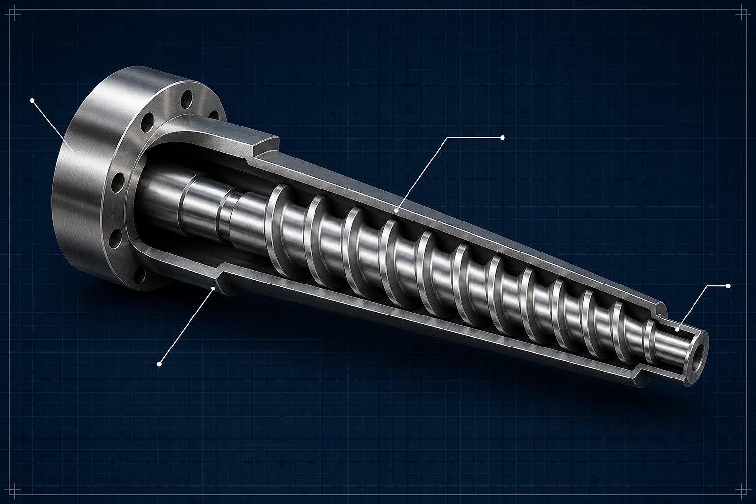
Taper angle is the starting point. It describes the angle at which each screw narrows from the feed end to the discharge end. In a conical screw extruder, this angle is typically subtle - just enough to create progressive compression without a drastic reduction in channel volume over a short distance. Think of it as the slope of the cone. A steeper taper produces more aggressive compression over a shorter screw length, while a shallower taper provides gentler, more gradual densification. The taper angle also determines the overall machine length: for a given diameter range, steeper tapers result in shorter extruder screws, contributing to the compact footprint conical machines are known for.
Flight depth (sometimes called channel depth) measures the distance from the top of the screw flight - the raised helical ridge that wraps around the screw - down to the root, or core, of the screw shaft. In a parallel design, flight depth is typically constant within each functional zone (feed, transition, metering). In a conical system, flight depth changes continuously along the screw length because the root diameter stays relatively thick while the outer diameter decreases. The result? Channel volume shrinks naturally from feed to discharge, eliminating the need for abrupt flight-depth reductions that create shear spikes in conventional screw designs.
Compression ratio quantifies exactly how much the material gets squeezed. It is the ratio of channel volume per unit length at the feed end to channel volume per unit length at the discharge end. A conical twin-screw extruder machine achieves its compression ratio primarily through the taper itself, rather than through dramatic changes in flight depth or pitch. Typical compression ratios for PVC processing fall in the range of 2.0:1 to 3.0:1, though manufacturers customize this ratio to match specific formulation bulk densities and processing behaviors. A higher ratio compacts low-density powders more aggressively - useful for fluffy dry blends - while a lower ratio suits pre-densified or pelletized feedstocks that need less volume reduction.
L/D ratio (length-to-diameter ratio) is where conical machines cause the most confusion. On a parallel extruder, it is straightforward: total screw length divided by screw diameter. Both numbers are constants, so L/D is a single, clean figure - commonly ranging from 28:1 to 52:1 for parallel twin screw systems. On a conical screw, the diameter is not constant. Industry practice typically expresses L/D relative to the large feed-end diameter, which yields ratios in the range of roughly 6:1 to 9:1. That number looks dramatically short compared to parallel machines, but it reflects a different measurement convention rather than a proportionally shorter processing path. The effective processing length of a conical system is shorter by design - and intentionally so. Reduced residence time limits thermal exposure for heat-sensitive polymers, which is exactly what PVC and WPC demand.
One more parameter worth understanding: screw speed range. Conical twin screw extruders operate at far lower rotational speeds than their parallel counterparts - typically 20 to 50 rpm versus 100 to 600 rpm for parallel machines. Lower speed means less frictional heat, less mechanical stress on the polymer, and quieter operation on the production floor. Output is maintained not through speed but through the large channel volume at the feed end and efficient pressure buildup along the taper.
| Parameter | Definition | Typical Range or Significance in Conical Designs |
|---|---|---|
| Taper Angle | The angle of convergence from the large feed-end diameter to the smaller discharge-end diameter | Determines compression aggressiveness and overall machine length; subtle angles produce gentler, more gradual compression |
| Feed-End / Discharge-End Diameter | Outer diameters of the screw at the inlet and outlet, expressed as a ratio (e.g., 65/132) | Common sizes include 45/90, 50/105, 55/100, 65/132, 80/143, 80/158, and 92/188 mm |
| Flight Depth (Channel Depth) | Distance from the flight tip to the screw root; determines the volume available for material transport | Decreases continuously along the taper rather than in stepped zones; deeper at the feed end, shallower at the discharge end |
| Compression Ratio | Ratio of feed-zone channel volume per unit length to discharge-zone channel volume per unit length | Typically 2.0:1 to 3.0:1 for PVC; customized per formulation to match bulk density and fusion behavior |
| L/D Ratio | Screw length divided by diameter; expressed relative to the large-end diameter for conical screws | 6:1 to 9:1 (large-end basis); shorter than parallel designs (28:1 to 52:1) to minimize residence time |
| Screw Speed (RPM) | Rotational speed of the screws during operation | 20 to 50 rpm; low speed reduces frictional heat and shear stress, critical for PVC thermal stability |
| Output Capacity | Mass throughput rate of processed material | Approximately 50 to 800+ kg/h depending on screw diameter; larger sizes (80/158, 92/188) reach higher throughputs |
| Screw Material and Hardness | Base alloy and surface treatment determining wear resistance and service life | 38CrMoAlA nitrided steel with surface hardness of HV 950-1000; optional bimetallic or chrome-plated treatments for abrasive compounds |
Barrel Zones and Temperature Control in Conical Systems
Here is something most equipment guides never mention: the tapered barrel's changing cross-section fundamentally alters how heat distributes through the material. Imagine a cylindrical barrel with uniform diameter - the ratio of heated barrel surface area to material volume stays roughly constant along its length. A conical barrel breaks that relationship. At the wide feed end, there is a large volume of cold, unplasticized powder surrounded by a proportionally large heated surface. As material advances into the narrowing section, the volume decreases faster than the surface area, meaning the barrel wall has proportionally more thermal influence per unit of material. In practical terms, heat penetrates the melt more efficiently toward the discharge end, right where the material needs to reach its final processing temperature.
Most conical twin screw extruder machines divide the barrel into three to five independently controlled heating and cooling zones. A typical temperature profile for rigid PVC might start at 150-160°C at the feed zone - just warm enough to begin softening the powder without premature fusion that would block material flow. Middle zones ramp up to 170-185°C, driving the fusion process through the primary compression region. The final zone near the discharge often holds steady or even drops slightly, typically settling around 175-190°C, to stabilize melt temperature before it enters the die.
Cooling is as important as heating. Each barrel zone usually features both electrical heating elements and cooling channels (water or oil circulation) so that temperature can be pulled down quickly if frictional heat from compression and shear begins pushing the melt above target. This dual-action control is essential because the conical geometry concentrates mechanical energy toward the narrowing discharge section, where compressive forces are highest. Without responsive cooling in that zone, the material risks overheating - especially during production startups or speed transitions.
Melt homogeneity benefits from this arrangement. Because the narrowing channel forces material closer to the heated barrel wall, temperature differentials between the center and periphery of the melt stream decrease as the material approaches the die. The result is a more uniform melt temperature across the full cross-section of the extrudate, which directly translates into better dimensional stability and surface quality in the finished product. Published melt temperature measurements on well-maintained conical systems show variation as tight as plus or minus 2 to 4 degrees Celsius at the die - a level of consistency that supports the tight tolerances demanded by PVC pipe and profile production.
These specifications are not abstract numbers on a datasheet. They define exactly how material transforms from loose powder to finished melt inside the barrel - and they determine the quality of every product the machine produces. When those specifications begin to drift due to wear on the extruder screws or barrel surfaces, the effects show up directly in your output quality. Recognizing what those end products should look like, and what the extruder contributes to achieving that standard, is the next critical piece of the puzzle.
End-Product Applications From PVC Pipe to WPC Decking
Specifications only matter if they produce real products that meet real standards. A conical twin screw extruder never operates in isolation - it sits at the center of a complete extrusion line, feeding molten material into a die that shapes it, followed by calibration tables that lock in dimensions, haul-offs that pull the product forward, and cutters that deliver finished pieces. Every application listed below depends on the extruder delivering a consistent, thermally uniform melt - and the conical design's gentle, progressive processing is what makes that possible across such a diverse product range.
Here are the major application categories, each with its own quality demands that the conical geometry directly supports:
- PVC pressure and drainage pipe - Requires tight wall thickness tolerances, smooth inner surfaces for low friction loss, and zero porosity to pass hydrostatic burst testing. Even minor melt inconsistency creates weak spots that fail under pressure.
- PVC window and door profiles - Demands complex multi-chamber cross-sections with sharp corners, uniform wall distribution, and flawless surface finish. Dimensional accuracy must hold within fractions of a millimeter across profiles that may include five or more internal chambers.
- PVC sheet and film - Calls for uniform gauge across the full sheet width, absence of gels or unplasticized particles, and consistent optical clarity (for transparent grades). Melt temperature variation shows up immediately as visible streaks or thickness bands.
- WPC decking and cladding - Needs thorough encapsulation of wood fiber within the polymer matrix, absence of internal voids caused by moisture, and surface hardness sufficient to resist foot traffic and weathering.
- PVC electrical conduit - Requires consistent concentricity, smooth interior for cable pulling, and mechanical toughness to survive installation bending without cracking.
PVC Pipe and Profile Extrusion Applications
Imagine producing a six-meter length of 110 mm PVC drainage pipe. The wall thickness specification might call for 3.2 mm plus or minus 0.2 mm - consistently, hour after hour, across an entire production shift. That tolerance depends entirely on how uniformly the extruder plasticizes the PVC dry blend and how steadily it delivers melt to the pipe die. Any fluctuation in melt pressure, temperature, or viscosity translates directly into wall thickness variation that either fails quality inspection or, worse, passes inspection and fails in the field.
The conical twin screw extruder's contribution here is fundamental. Its counter-rotating screws create the positive-displacement pumping action that delivers melt at a stable, predictable flow rate. The progressive compression along the taper ensures the PVC powder fuses thoroughly without hot spots or cold slugs that would create weak zones in the pipe wall. Downstream, the twin screw extruder plastic melt passes through a spider or spiral mandrel die, enters a vacuum calibration tank that freezes the outer diameter to specification, then moves through spray cooling baths before a caterpillar haul-off pulls it at a precisely controlled speed. The cutter at the end produces finished lengths. Every station matters, but if the extruder feeds inconsistent melt, no amount of downstream adjustment rescues the product.
Profile extrusion raises the bar even further. A PVC window frame profile might feature five hollow chambers separated by thin internal walls as narrow as 1.2 mm. The melt must flow evenly through every channel of a complex profile die, filling thin sections and thick sections simultaneously without one area starving while another overpacks. This demands not just uniform melt temperature but uniform melt viscosity - and that only happens when the twin screw compounding extruder upstream delivers a completely homogeneous fusion. Conical machines excel here because their low screw speeds, typically 20 to 40 rpm, generate minimal shear-induced temperature variation. The melt arriving at the die is remarkably consistent, which is exactly why conical extruders dominate the PVC profile sector globally.
WPC and Sheet Extrusion Production Lines
WPC decking production showcases the conical extruder's versatility beyond pure PVC. A typical WPC decking extrusion line centers on a conical twin-screw extruder - commonly an SJSZ-65/132 or SJSZ-80/156 - processing a powder compound of wood flour, PVC or PE resin, and functional additives directly from a high-speed mixer. The line then continues through a custom decking die, a vacuum calibration table spanning four to six meters, spray cooling tanks, a caterpillar haul-off, and a traveling cut-off saw.
What makes the conical design particularly valuable for WPC? Consider the compound itself: 40 to 60 percent wood flour by weight, producing a bulky, low-density blend that feeds poorly into narrow-bore extruders. The conical machine's wide feed opening handles this effortlessly. Meanwhile, screw speeds stay low - typically 18 to 32 rpm for WPC - limiting the frictional heat that would otherwise scorch wood fibers and release volatile gases that cause surface defects. Compound moisture content must stay below 0.3 to 0.5 percent before it reaches the extruder, because steam trapped in the melt creates porosity and blistering that no downstream correction fixes.
PVC sheet extrusion follows a similar principle but with different downstream equipment. Instead of a pipe or profile die, the extruder feeds a flat sheet die followed by a polishing and calendering stack that determines final thickness, surface gloss, and flatness. Sheet applications demand an exceptionally consistent melt because any variation in flow rate causes cross-web thickness bands - defects visible to the naked eye that render the sheet unusable for thermoforming, signage, or cladding applications.
Across all these applications, the conical twin screw barrel plays a critical role in maintaining production quality over time. As barrels and screws wear, the tight clearances that ensure positive conveying and uniform compression gradually open up, leading to melt inconsistency and declining product quality. For manufacturers seeking custom or replacement barrels to restore production performance across PVC pipe, profile, sheet, or WPC applications, NANHAIYA's Conical Twin Screw Barrel offers purpose-built solutions designed to match original equipment specifications and support consistent plasticizing over extended service life.
Whether you are running pipe at 500 kg/h or WPC decking at 200 kg/h, the extruder remains the heartbeat of the line. Every downstream station depends on what it delivers. And when that delivery begins to falter - when output drops, melt quality drifts, or energy consumption climbs - the cause almost always traces back to wear patterns inside the barrel and on the screw surfaces. Understanding where and why that wear occurs is essential for keeping production on target.
Maintenance and Wear Patterns in Conical Twin Screw Systems
A conical twin screw extruder does not fail all at once. It degrades gradually - screw flights lose their sharp edges, barrel bores open up by hundredths of a millimeter, and clearances that were once tight enough to ensure positive conveying slowly widen. The insidious part? Production often continues looking acceptable until wear crosses a threshold where output drops, melt quality drifts, and energy costs climb - sometimes all within the same week. Knowing where wear happens, why it accelerates, and when it has gone too far is the difference between planned maintenance and emergency downtime.
Wear Patterns Unique to Conical Screw and Barrel Sets
Not all sections of a conical barrel wear at the same rate. The tapered geometry creates distinct mechanical environments along the screw length, and each zone degrades through different mechanisms. Understanding these patterns helps you inspect smarter and predict replacement timelines more accurately.
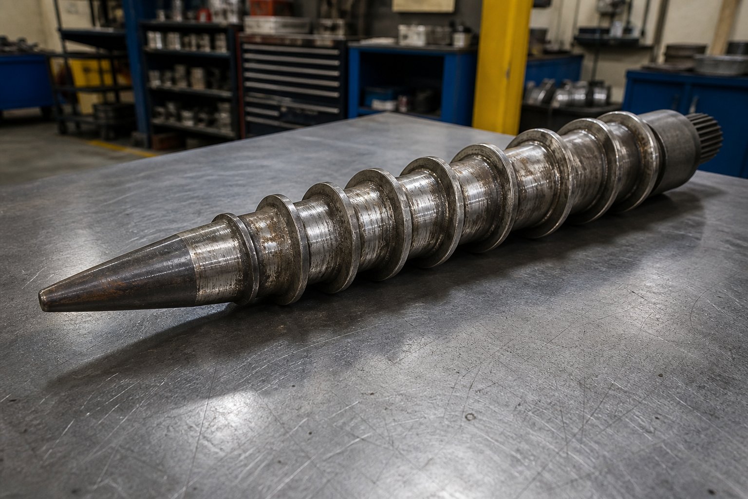
The high-compression transition zone takes the heaviest beating. This is the region roughly one-third to two-thirds of the way along the screw, where the taper narrows most actively and material transitions from a loosely packed powder into a densifying, partially fused mass. Compressive forces peak here. Unmelted PVC grains - still hard and abrasive - are being squeezed against the barrel wall and the screw flights simultaneously. The result is classic abrasive wear: sharp flight edges round off, channel depth increases beyond specification, and the barrel bore gradually enlarges. This is the most common type of wear in twin-screw extruders, and it directly correlates with throughput volume rather than operating hours alone.
The discharge end faces a different challenge. Here, the fully plasticized melt is under maximum pressure as it pushes toward the die. The narrow screw diameter at this point means thinner flights and reduced structural rigidity, making the screw tips more vulnerable to deflection. When screws flex even slightly, their outer flights contact the barrel wall - a condition that produces adhesive wear. You will see flattened flight tips and score marks on the barrel surface, sometimes with a polished, burnished appearance that might look harmless but indicates metal-to-metal contact that accelerates rapidly once it starts.
The feed zone wears least in standard PVC processing because material here is still loose powder exerting minimal mechanical pressure. However, if your formulation contains hard mineral fillers like calcium carbonate at high loadings, or abrasive pigments like titanium dioxide, even the feed section will show measurable erosion over time. The sharp-edged particles act like sandpaper against flight surfaces from the moment they enter the machine.
Corrosive wear deserves a mention too, though it is less common in well-managed PVC operations. If PVC degrades thermally inside the barrel - even locally - it releases hydrochloric acid gas. That gas attacks metal surfaces, creating pitting and surface roughness that then accelerates abrasive wear. This combination of corrosion and abrasion is especially destructive because each mechanism amplifies the other: pitted surfaces trap abrasive particles, and abraded surfaces lose their protective oxide or nitride layer faster.
How Material Selection Extends Service Life
The metallurgy of your screw extruders and barrels determines how long they resist these wear mechanisms. Two dominant approaches exist, each suited to different processing demands.
Nitrided steel - typically 38CrMoAlA alloy - is the standard for most PVC processing applications. The nitriding process diffuses nitrogen into the surface layer, creating a hard case (HV 950 to 1,000 on the Vickers scale) over a tough, ductile core. This combination resists abrasive wear effectively while maintaining the structural toughness needed to handle compressive and torsional loads. For operations running standard PVC pipe or profile compounds with moderate filler loadings, nitrided screws and barrels typically deliver two to four years of service before clearances open enough to affect output quality.
Bimetallic linings step up protection for more demanding applications. In this construction, the barrel bore is lined with a centrifugally cast alloy - often a nickel- or cobalt-based material with embedded hard carbide particles - that provides significantly higher abrasion and corrosion resistance than nitriding alone. Bimetallic barrels are the go-to choice for WPC processing, where abrasive wood fibers chew through nitrided surfaces at two to three times the rate seen in pure PVC work. They also make sense for recycled PVC containing unknown contaminants - metal particles, glass fibers, or degraded filler agglomerates - that unpredictably spike abrasive loading.
Chrome plating offers a middle ground for some processors, providing a smooth, corrosion-resistant surface layer. However, chrome layers are relatively thin and can chip or flake under severe abrasive conditions, making them better suited for corrosion protection than as a primary abrasion defense.
Preventive Maintenance Practices That Pay Off
Waiting until product quality deteriorates is reactive maintenance - and it is expensive. Preventive practices catch problems early and keep replacement costs predictable rather than catastrophic.
Regular inspection intervals are the foundation. A monthly visual check of the screw flights and barrel bore - or at minimum during every scheduled production changeover - lets you track wear progression before it impacts output. As a practical best practice, clean the screws and barrel after each production run to remove residual material that could harden and accelerate wear. Look for rounded flight edges, polished contact marks, and any visible pitting. Measure critical dimensions with calipers or wear gauges if available - a 5 percent increase in barrel bore diameter over a length of one screw diameter, or a 5 percent reduction in screw flight outer diameter over three-quarters of the element length, are practical thresholds that signal replacement is approaching.
Proper shutdown procedures protect screw and barrel surfaces during non-production periods. When screws rotate without material present, the molten resin that normally supports the shafts and prevents metal-to-metal contact is absent. Running screws dry, even briefly, causes adhesive wear that accumulates over repeated start-stop cycles. Best practice is to purge the barrel thoroughly with a cleaning compound at reduced speed, then stop screw rotation before the barrel is fully empty. If your machine lacks an automatic shutdown feature, train operators to ramp down screw speed and stop rotation before the torque drops below a safe threshold.
Alignment checks matter more on conical systems than many operators realize. Because the tapered screws converge toward the discharge end, even minor misalignment between the screws and barrel concentrates contact forces on one side. Over time, this produces asymmetric wear - one side of the barrel bore opens faster than the other, and one screw's flights wear unevenly. Checking alignment during screw reinstallation, and verifying gearbox shaft positioning during annual overhauls, prevents this avoidable damage pattern.
Lubrication and drive system care round out the essentials. Gearbox oil levels, bearing condition, and thrust bearing preload all influence how smoothly the screws rotate within the barrel. A worn thrust bearing allows axial play that changes the effective clearance between the screw tips and the barrel end cap - a subtle shift that can cause localized overheating and accelerated wear at the discharge end.
When to Replace Your Conical Twin Screw Barrel
Replacement timing is ultimately a cost-benefit calculation: the expense of new components versus the accumulating losses from declining output, increased scrap rates, and rising energy consumption. But the performance signals are unmistakable once you know what to look for.
- Reduced output rate - When throughput drops 10 to 15 percent or more at the same screw speed and temperature settings, worn clearances are allowing material to leak back over the flights instead of being conveyed forward. You are running the motor harder for less product.
- Poor melt homogeneity - Unmelted particles (commonly called "fish eyes" in PVC processing), streaking, or inconsistent surface gloss in the extrudate indicate that the screws can no longer generate sufficient compression and mixing to fully fuse the compound.
- Increased motor load - A gradual rise in amperage draw at constant operating conditions suggests the drive is working harder to compensate for lost pumping efficiency. Worn screws slip more, requiring more energy to maintain output.
- Visible screw surface damage - Rounded flight tips, deep scoring, pitting from corrosive attack, or measurable diameter reduction beyond the 5 percent guideline all confirm that the screw geometry has departed from its design intent. At this stage, the screw is no longer creating the compression ratio and channel geometry your process requires.
- Dimensional instability in the product - Wall thickness variation in pipe, weight fluctuation in profiles, or gauge banding in sheet that cannot be corrected through process adjustments often traces back to inconsistent melt delivery caused by worn screw and barrel surfaces.
When these indicators converge, replacing the screw and barrel set together is almost always more cost-effective than replacing one component at a time. A new screw in a worn barrel - or vice versa - creates mismatched clearances that compromise performance and accelerate wear on the new part. For PVC and WPC processors facing wear-related production decline, sourcing precision-manufactured replacement components is critical. NANHAIYA's Conical Twin Screw Barrel offers custom and replacement barrels built to match original equipment dimensions, supporting the tight clearances that restore consistent plasticizing and output stability across pipe, profile, sheet, and WPC extrusion applications.
Keeping your barrel and screws in specification keeps your process in control. But even well-maintained equipment encounters operational problems that are not strictly wear-related - temperature excursions, feed inconsistencies, and melt quality issues that demand a systematic troubleshooting approach rather than a parts order.
Troubleshooting Common Conical Twin Screw Extruder Problems
Worn screws and barrels are not the only things that disrupt production. Operational problems - output swings, discolored extrudate, uneven melt, or a motor alarm that trips mid-shift - can strike even on well-maintained equipment. The challenge is not recognizing that something is wrong; the challenge is isolating why. A systematic diagnostic approach, working from the feed hopper through each barrel zone to the die, prevents the expensive guesswork that turns a one-hour fix into a full-day shutdown.
Whether you are running a full-scale production extruder twin screw system or validating formulations on a laboratory twin screw extruder before scaling up, the diagnostic logic follows the same sequence. The symptoms might appear at the die, but the root cause almost always lives upstream.
Diagnosing Output Inconsistency and Surging
Output surging - a rhythmic or irregular fluctuation in extrudate volume - is one of the most common complaints on conical twin screw lines. You notice it as pulsating strand diameter at the die, fluctuating melt pressure readings, or periodic wall thickness variation in pipe or profile. The temptation is to adjust screw speed or die temperature, but that often masks the real cause rather than resolving it.
Start your diagnosis at the feed system. Powder bridging in the hopper is the single most frequent cause of output instability on conical extruders processing PVC dry blends. The low-bulk-density powder clumps against the hopper walls or forms a stable arch above the feed throat, creating intermittent starvation cycles. Check for material buildup visually - if the hopper is warm from conducted barrel heat, condensation can cause powder to cake on the walls. Installing a hopper agitator or vibrator, or simply adding a feed throat cooling jacket, often eliminates the problem entirely.
If the feed system checks out clean, move downstream. Inconsistent barrel zone temperatures - particularly in the compression zone where material transitions from powder to melt - produce surging because the polymer's viscosity swings with temperature. A thermocouple that has drifted out of calibration by just 5 to 8 degrees Celsius can create enough melt viscosity variation to produce visible output fluctuation. Cross-check your barrel zone readouts against a calibrated handheld thermometer to confirm accuracy, and inspect heater bands for cracked elements or loose electrical connections.
Screw wear is the third suspect, and the hardest to check without pulling the screws. As flight tips round off and clearances increase, some material slips backward over the flights instead of being conveyed forward. This creates an internal recirculation loop that oscillates with pressure changes, producing the characteristic surging pattern. If output instability appeared gradually over weeks or months rather than suddenly, worn screw geometry is the most likely culprit - and the troubleshooting table below maps this and other symptoms to their corrective actions.
Preventing Material Degradation and Overheating
Degradation in PVC processing announces itself through unmistakable signs: yellow or brown discoloration, black specks in the extrudate, a sharp acidic smell near the die, or a hazy, rough surface finish on what should be a smooth product. Each of these signals tells you that material temperature exceeded the safe processing window somewhere inside the barrel - even if your zone temperature setpoints look correct on the control panel.
The conical barrel's temperature zones should follow a deliberate ascending-then-stabilizing profile. A typical starting point for rigid PVC is 150 to 160 degrees Celsius in the feed zone, ramping to 170 to 185 degrees through the compression zones, and holding or stepping back slightly to 175 to 190 degrees near the discharge. If a zone is set too high relative to its neighbors, it creates a localized hot spot where PVC molecules begin decomposing. The released hydrochloric acid then accelerates degradation in a chain reaction - and by the time you smell it, damage is already underway.
Excessive residence time compounds the problem. If screw speed drops too low relative to output, or if material accumulates in dead spots within the barrel or die adapter, polymer sits at elevated temperatures longer than it can tolerate. Even a benchtop twin screw extruder used for formulation development encounters this issue at low throughput settings - the small material volume per revolution means each gram spends more time inside the heated barrel. On production-scale machines, dead spots typically form at flanged barrel joints or at transitions between the screw tips and the die entry. Removing and inspecting the die adapter and breaker plate during routine maintenance helps identify and eliminate these stagnation zones before they cause chronic degradation.
Early detection is your best defense. Monitor motor amperage trends: a slow decline in amps at constant settings can indicate the material is degrading and losing viscosity, flowing more easily through the barrel because it is partially breaking down. Track melt temperature at the die with an immersion thermocouple rather than relying solely on barrel zone readings - actual melt temperature often runs 5 to 15 degrees higher than setpoint due to frictional heat, and that gap matters enormously for PVC.
The following table consolidates the most common operational symptoms, their likely causes, and recommended corrective actions into a single scannable reference. Keep it accessible to your operators - troubleshooting speed drops dramatically when the diagnostic path is already mapped out.
| Symptom | Likely Causes | Recommended Corrective Actions |
|---|---|---|
| Output surging or pulsating extrudate | Hopper bridging or inconsistent powder feed; drifted thermocouple readings causing temperature swings in the compression zone; worn screw flights allowing material backflow | Inspect hopper for material buildup and install agitator or feed throat cooling; calibrate all thermocouples against a reference instrument; pull screws and measure flight dimensions against wear limits |
| Yellow or brown discoloration in extrudate | Barrel zone temperature set too high; excessive residence time from low screw speed or dead spots; degraded material trapped in die adapter or breaker plate | Reduce overheated zone temperatures in 3 to 5 degree increments; increase screw speed to reduce residence time; disassemble and thoroughly clean die adapter and breaker plate |
| Black specks or carbonized particles | Carbonized residue from previous runs breaking loose; material stagnation in barrel corners or at flanged joints; inadequate purging during material changeovers | Perform a thorough barrel and screw purge with a cleaning compound; inspect and polish barrel bore at flanged joints; establish purge protocols between production runs |
| Poor melt homogeneity or "fish eyes" | Worn screws no longer generating adequate compression; incorrect temperature profile with insufficient heat in early zones; inconsistent raw material particle size or moisture content | Replace screw and barrel set if clearances exceed wear limits; raise feed and transition zone temperatures to promote earlier fusion; verify raw material specifications and pre-dry if needed |
| Excessive motor load or frequent overload trips | Overfeeding beyond extruder capacity; cold-start operation without adequate barrel preheating; worn gearbox bearings increasing mechanical friction; highly filled compound exceeding torque limits | Reduce feed rate and verify it matches rated throughput; ensure all barrel zones reach setpoint before starting screw rotation; inspect gearbox lubrication and bearing condition; adjust formulation or reduce filler loading |
| Rough or hazy surface finish on extrudate | Incomplete plasticizing due to low barrel temperatures or excessive screw speed; die surface buildup or plate lip damage; moisture in the feedstock generating micro-voids | Increase metering zone temperature to ensure complete fusion; clean and polish die land surfaces; pre-dry feedstock to below 0.1 percent moisture content |
| Unusual noise or vibration from the extruder | Foreign metal contamination in the barrel; misaligned screws contacting the barrel wall; worn gearbox gears or bearings; loose barrel flange bolts | Immediately reduce screw speed and shut down for inspection; remove and inspect screws for scoring or foreign object damage; check screw alignment and gearbox condition; tighten all mechanical fasteners to specification |
Troubleshooting is most effective when it builds on the operator's familiarity with baseline performance. Document your normal operating parameters - motor amps, melt pressure, zone temperatures, and output rate - during stable production runs. When something drifts, compare current readings against that baseline rather than guessing at what "normal" should be. This data-driven approach, combined with the systematic feed-to-die diagnostic sequence, turns reactive firefighting into methodical problem-solving that minimizes downtime and protects both product quality and equipment longevity.
Practical Guidance for Selecting and Operating Conical Extruders
Diagnosing problems on the production floor is reactive by nature - even the best troubleshooting only restores what you already had. The more consequential decisions happen earlier: when you select the machine, configure the line, and plan the maintenance calendar that determines whether that equipment delivers value for five years or fifteen. Whether you are evaluating a twin screw extruder for sale, optimizing an existing line, or trying to understand where this technology fits in the broader extrusion landscape, the principles below distill everything covered in this article into decisions you can act on.
Key Takeaways for Engineers and Plant Managers
Different roles demand different priorities. An engineer specifying equipment cares about screw geometry and process parameters. A plant manager cares about uptime, cost per kilogram, and whether the machine will still perform well in year eight. A newcomer just needs to know which questions to ask. Here is what matters most for each.
For process engineers: Screw geometry is your primary lever. Matching the taper angle, compression ratio, and flight depth profile to your specific formulation's bulk density and fusion characteristics determines whether the machine runs smoothly or fights you every shift. Do not accept generic screw designs when your formulation includes unusual filler loadings or non-standard particle sizes - request geometry customized to your actual feedstock. Remember that the conical design's low screw speeds (20 to 50 rpm) mean your temperature profile does the heavy lifting on plasticizing. Invest time in optimizing zone temperatures rather than pushing screw speed to compensate for under-heated material.
For plant managers: Purchase price is the smallest part of the equation. A conical twin screw extruder's Total Cost of Ownership (TCO) - energy consumption, maintenance intervals, screw and barrel replacement cycles, and downtime costs - dwarfs the initial capital outlay over a machine's 15- to 20-year service life. A machine that costs 10 percent less upfront but consumes 15 percent more energy and requires barrel replacement a year earlier is the more expensive option by a wide margin. Schedule preventive maintenance based on throughput volume, not calendar time. A machine processing abrasive WPC compounds at 400 kg/h wears faster than one running unfilled PVC at the same rate - your inspection intervals should reflect that difference.
For newcomers: The conical twin screw extruder is not a universally superior machine. It is a specialized tool engineered for specific problems - low-bulk-density powder feeding, heat-sensitive polymer processing, and compact-footprint production lines. If your application involves high-shear compounding of engineering plastics or multi-ton-per-hour throughput, a parallel configuration is likely the better fit. Understanding this distinction early prevents costly mismatches and helps you ask the right questions when talking to any twin-screw extruder manufacturer.
Choosing the Right Conical Twin Screw Setup for Your Production Goals
Beyond role-specific priorities, several practical considerations rarely appear in equipment brochures but genuinely affect daily operations.
Energy efficiency benefits from the conical design's compact architecture. A shorter barrel means fewer heating zones drawing power, less surface area losing heat to the ambient environment, and a smaller motor driving screws at low rpm. Combined with modern VFD-controlled drives and insulated barrel jackets, a well-configured conical system can achieve specific energy consumption figures that make economic sense even against larger parallel machines running at higher absolute throughputs. When evaluating a used twin screw extruder for sale, check the drive system vintage - upgrading an older fixed-speed motor to a variable frequency drive often pays for itself within 12 to 18 months through energy savings alone.
Floor space is a constraint that spreadsheets tend to undervalue. A conical extruder's shorter overall length frees room for downstream equipment, material staging, or future line expansion. In facilities where square meters carry a real cost - leased buildings, climate-controlled environments, or crowded multi-line operations - this compactness translates directly into financial advantage.
Noise levels matter more than most equipment guides acknowledge. Conical machines running at 20 to 45 rpm generate significantly less mechanical noise than parallel designs operating at 300 to 600 rpm. In plant environments where operators work near the equipment for full shifts, that difference affects worker comfort, communication clarity, and compliance with occupational noise exposure limits - practical realities that influence workforce retention and regulatory standing.
When the time comes to commit, these five criteria - ranked by their long-term impact on production success - provide a decision framework that keeps you focused on what actually drives value:
- Material compatibility - Confirm that your primary feedstock (PVC dry blend, WPC compound, recycled PVC) falls within the conical design's strengths: low-shear, positive-conveying, progressive-compression processing for heat-sensitive or low-bulk-density materials.
- Screw geometry match - Verify that the screw diameter ratio, compression ratio, and taper angle align with your formulation's bulk density and fusion behavior. Generic sizing leads to underperformance; request application-specific recommendations from the manufacturer.
- Total Cost of Ownership - Calculate energy, maintenance, and replacement costs over at least a 10-year horizon. Compare machines on cost-per-kilogram of saleable output, not purchase price alone.
- Output capacity versus production targets - Size the extruder to run at 70 to 80 percent of its rated capacity during normal production. Running at maximum continuously accelerates wear and eliminates your margin for handling formulation changes or production surges.
- Supplier support and spare parts availability - Evaluate how quickly the manufacturer or parts supplier can deliver replacement screws, barrels, and drive components. A 48-hour turnaround on critical spares is worth more than a marginal price discount on the initial purchase.
Understanding conical twin screw extruder fundamentals - from tapered geometry and counter-rotating mechanics to wear patterns and material suitability - transforms equipment decisions from guesswork into engineering judgment, and that clarity is what separates production lines that merely run from those that consistently deliver.
The taper changes everything - not because it is complex, but because it is precisely matched to the materials and applications that demand it. Whether you are specifying your first conical line, extending the life of an existing one, or deciding between conical and parallel for a new project, the principles outlined throughout this guide give you the technical grounding to make that decision with confidence.
Frequently Asked Questions About Conical Twin Screw Extruders
1. What is the difference between a conical and parallel twin screw extruder?
A conical twin screw extruder uses two tapered screws that are wider at the feed end and narrower at the discharge end, housed in a matching conical barrel. A parallel twin screw extruder features two uniform-diameter screws in a straight cylindrical barrel. The conical design excels at feeding low-bulk-density powders like PVC dry blends, offers a more compact footprint, and delivers gentle, low-shear processing ideal for heat-sensitive polymers. Parallel designs provide higher mixing intensity, modular barrel configurations, and better scalability for high-volume compounding of engineering plastics. Choosing between them depends on your feedstock type, required output volume, and end-product quality demands.
2. Why are conical twin screw extruders preferred for PVC processing?
PVC has an extremely narrow safe processing window - typically between 170 degrees C and 200 degrees C - and degrades rapidly if overheated, releasing corrosive hydrochloric acid. Conical twin screw extruders address this challenge through three key features: counter-rotating screws that provide gentle, positive-displacement conveying with minimal shear heat generation; a tapered geometry that progressively compresses the powder without sudden pressure spikes; and low operating speeds of 20 to 50 rpm that limit frictional heating. Together, these characteristics ensure uniform fusion of PVC powder grains while keeping the material safely within its thermal processing window.
3. How often should conical twin screw barrels and screws be replaced?
Replacement intervals depend on the material being processed, filler content, and throughput volume rather than calendar time alone. For standard PVC pipe or profile compounds with moderate filler loadings, nitrided screw and barrel sets typically last two to four years before clearances affect output quality. Abrasive applications like WPC or heavily filled PVC compounds accelerate wear significantly. Key replacement indicators include a 10 to 15 percent drop in output at constant settings, visible fish eyes or streaking in the extrudate, rising motor amperage, and measurable screw flight diameter reduction beyond 5 percent. Replacing screws and barrels as matched sets - rather than individually - ensures proper clearances and avoids premature wear on new components. Suppliers like NANHAIYA (nhyscrews.com) offer custom replacement conical twin screw barrels built to original equipment dimensions.
4. What materials can be processed on a conical twin screw extruder?
Conical twin screw extruders are optimized for heat-sensitive and low-bulk-density feedstocks. Rigid PVC (uPVC) is the most common material, followed by flexible (plasticized) PVC, wood-plastic composites containing 40 to 70 percent wood flour, and recycled PVC with variable quality. Other thermoplastics like PP, PE, and ABS can also be processed, though these materials do not fully leverage the conical design's core advantages. Materials requiring intensive dispersive mixing or high-shear compounding - such as engineering plastics, masterbatch with high pigment loadings, or reactive extrusion feedstocks - are generally better suited for parallel twin screw extruders.
5. What does the L/D ratio mean on a conical twin screw extruder?
The L/D ratio on a conical twin screw extruder represents screw length divided by the large feed-end diameter, typically falling between 6:1 and 9:1. This appears much shorter than the 28:1 to 52:1 range common on parallel twin screw extruders, but the difference reflects a different measurement convention rather than a proportionally shorter processing path. The intentionally shorter effective length reduces material residence time inside the heated barrel, which directly benefits heat-sensitive polymers like PVC by limiting thermal exposure. Common conical screw size designations - such as 65/132 or 80/156 - express the discharge-end and feed-end diameters in millimeters, giving a quick indication of both the machine's intake capacity and its compression characteristics.
Written by
Nanhaiya Technical Team
Zhoushan Nanhaiya Plastic Machinery Co., Ltd.
The Nanhaiya technical team supports screw and barrel manufacturing projects through application review, technical communication, custom manufacturing coordination, and production and quality control.
Discuss Your Application
Related Articles
More insights on screw barrel technology and plastics processing.

Extruder Machine Decoded: From Raw Pellet To Finished Product
Oct 6, 2026
Learn how an extruder machine works, compare single-screw vs. twin-screw types, and get expert guidance on specs, troubleshooting, and selection.
Read Article
PE Pipe Making Machine Decoded: From Raw Resin to Flawless Pipe
Oct 4, 2026
Learn how a PE pipe making machine works, from resin to finished pipe. Covers components, material grades, automation, troubleshooting, and buyer selection tips.
Read Article
PVC Profile Making Machine Decoded: From Raw Resin To Profit
Oct 3, 2026
Learn how a PVC profile making machine works — extrusion process steps, key technical parameters, die design, calibration methods, maintenance, and total cost of ownership.
Read ArticleLooking for something else?
Search by material, symptom or product and jump straight to the relevant page.
These are navigation suggestions based on keyword matching — not a quotation, not a delivery commitment, and not a substitute for engineering review. Final specification is confirmed by our engineers against your drawings and processed material.
Need help with screw barrel selection?
Share your machine model, processed material and application. Our team can help with pricing and technical support.