

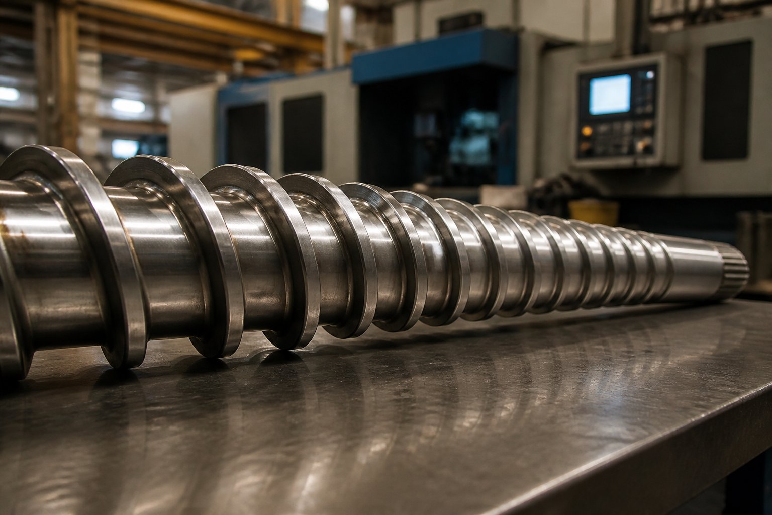
What Compression Ratio Means for Injection Molding Screws
Every plastic injection molding screw has a hidden personality trait baked into its geometry — one that quietly dictates whether your parts come out flawless or riddled with defects. That trait is the compression ratio, and most processors never give it a second thought.
Defining Compression Ratio on an Injection Molding Screw
In simple terms, compression ratio describes how aggressively the screw compacts and shears plastic as it travels from the hopper toward the nozzle. It is a volumetric ratio, not a pressure measurement, and it is determined entirely by two physical dimensions on the screw itself.
Compression ratio equals the channel depth in the feed zone divided by the channel depth in the metering zone (H1 ÷ H2). A screw with a 6 mm feed depth and a 2 mm metering depth, for example, has a 3:1 compression ratio.
The formula applies to all screws, yet its practical impact differs dramatically between injection molding and extrusion. An injection molding screw reciprocates — it rotates to plasticize resin, then slides forward like a plunger to inject the shot. That dual role changes how the compression profile interacts with the polymer during every cycle, making it critical to distinguish this context from continuous extrusion applications.
Why This Parameter Matters More Than Most Processors Realize
Here is a reality most molding shops share: the screw inside the machine is whatever came installed at the factory. Nobody measured its channel depths. Nobody checked whether the compression ratio suits the resin currently running through it. And when defects appear — splay, unmelts, discoloration, inconsistent shot weights — the troubleshooting checklist jumps straight to temperatures, pressures, and speeds. The screw geometry itself rarely gets questioned.
Yet compression ratio influences nearly everything downstream. A ratio that is too high generates excessive shear heat, risking degradation and burning. Too low, and the resin exits the metering zone with unmelted particles and trapped air. As industry experts have noted, the ratio determines the amount of heat, pressure, and shear applied to the plastic during plasticization — directly affecting melt uniformity, energy consumption, and part-to-part consistency.
This guide serves as a single, comprehensive reference for injection molding screws and their compression ratios. You will find clear calculation steps, resin-specific ratio recommendations, troubleshooting diagnostics, and guidance on how compression ratio interacts with screw diameter, L/D ratio, and flight geometry — all focused exclusively on injection molding rather than extrusion.
The starting point, naturally, is understanding exactly how to measure your screw and calculate the number yourself.
How to Calculate Injection Molding Screw Compression Ratio
Grab a caliper and pull your screw out of the barrel. That is the most direct way to answer a question most processors never ask: what compression ratio am I actually running? The math is straightforward, but the measurements need to be taken in the right places — and a surprising number of people get that part wrong.
Measuring Feed Zone and Metering Zone Channel Depths
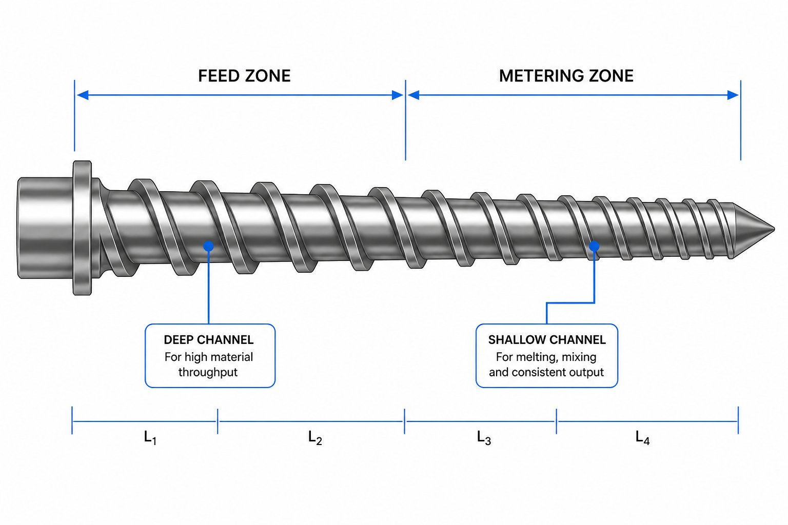
Every screw for injection molding machine applications has three recognizable zones along its length: the feed zone near the hopper end, the transition (or compression) zone in the middle, and the metering zone closest to the nozzle. You only care about two of them for this calculation — the feed zone and the metering zone — because those are the sections where the channel depth remains constant.
Channel depth is the radial distance from the screw root (the shaft surface at the bottom of the channel, between the flights) to the outer edge of the flight. You can measure it two ways:
- Direct depth measurement: Place a depth gauge or depth micrometer across the flight tops and drop it down to the root surface. This gives you channel depth directly.
- Diameter-based calculation: Measure the screw's outer diameter (across the flight tips) and the root diameter (the shaft diameter at the bottom of the channel) using a micrometer. Then apply the formula: Channel depth = (Outer diameter − Root diameter) ÷ 2.
The key detail to understand in an injection molding screw diagram is that the flight outer diameter stays the same along the entire screw — it matches the barrel bore. What changes is the root diameter. In the feed zone, the root is thinner, creating a deep channel. In the metering zone, the root is thicker, producing a shallow channel. That shrinking channel volume is precisely what creates compression.
Here is the step-by-step process to calculate the mm size injection molding screw compression ratio:
- Remove the screw from the barrel and clean off all residual resin. Place it on a flat, clean surface.
- Identify the feed zone. Look for the section near the shank (hopper end) where the channel depth is visibly deep and remains constant across several flights.
- Measure the feed channel depth (hf). Using a depth micrometer or the diameter method, take readings at two or three points within the constant-depth feed section and average them.
- Identify the metering zone. Move to the discharge end (nozzle side) and locate the section where the channel is shallow and consistent across several flights.
- Measure the metering channel depth (hm). Use the same technique, taking multiple readings and averaging.
- Divide. Compression ratio = hf ÷ hm.
Worked example: Imagine your screw has a flight outer diameter of 50 mm. In the feed zone, the root diameter measures 30 mm. In the metering zone, it measures 42 mm. Feed channel depth = (50 − 30) ÷ 2 = 10 mm. Metering channel depth = (50 − 42) ÷ 2 = 4 mm. Compression ratio = 10 ÷ 4 = 2.5:1.
Common Calculation Mistakes to Avoid
Simple as the formula is, several pitfalls routinely throw off the result — sometimes enough to lead a processor toward the wrong screw selection entirely.
Measuring in the transition zone. This is the most frequent error. The transition zone is where the root diameter is actively changing from flight to flight, so any measurement taken there captures a depth that belongs to neither the feed nor the metering section. As engineering references emphasize, you should measure only in the constant-depth portions of the feed and metering zones — never where the channel depth is visibly tapering.
Confusing flight depth with channel depth. Some technicians measure from the barrel wall to the root surface, which adds the flight-to-barrel clearance into the number. Channel depth is measured from the flight tip to the root, not from the barrel bore. Using barrel-referenced measurements inflates both depths and can mask the true ratio.
Ignoring screw wear. A worn screw has flight tips that have been ground down, reducing the effective outer diameter. That means the measured channel depth will be shallower than original, and the compression ratio you calculate will not reflect the screw's design intent. If you suspect wear, compare your measurements against the original drawing or OEM specification before drawing conclusions about feed screw design for injection molding suitability.
Treating the ratio as a pressure number. Compression ratio is a purely geometric relationship — a volumetric ratio describing how much the channel volume shrinks from feed to metering. It influences pressure, shear rate, and heat generation, but it is not itself a pressure measurement. Two screws with identical 2.5:1 ratios will produce very different actual pressures depending on resin viscosity, screw speed, and back pressure settings. Conflating the two leads to flawed troubleshooting logic.
One more scenario worth flagging: barrier screws and variable-pitch designs. On these specialized geometries, the simple depth-ratio formula does not capture the real compression behavior because the screw separates solid and melt into different channels. If your screw for injection molding machine use has a barrier flight, you will need the manufacturer's specification or original drawing to determine the effective compression ratio rather than relying on field measurements alone.
With a reliable number in hand, the next logical question becomes: is this ratio right for the resin you are running? Answering that requires understanding the material science that drives why different polymers demand different compression profiles.
The Physics Behind Why Different Polymers Need Different Ratios
A 2.5:1 compression ratio might be perfect for polystyrene and a disaster for nylon. Why? Because the screw does not simply push plastic forward — it must transform solid pellets into a uniform, fully molten stream. Different polymers resist that transformation in fundamentally different ways, and four physical properties determine how much compression is needed to get the job done.
- Bulk density ratio (solid vs. melt): The ratio of a resin's solid pellet bulk density to its melt density dictates how much volume reduction occurs during plasticization. A large gap between these two values means the screw channel must shrink significantly to squeeze out trapped air and consolidate the melt. Feed screws for injection molding must account for this gap, or air pockets and voids will persist into the shot.
- Crystalline vs. amorphous molecular structure: Whether a polymer's chains are ordered (semi-crystalline) or randomly tangled (amorphous) changes the entire melting mechanism. This difference alone can shift the ideal compression ratio by a full point or more.
- Melt viscosity: A polymer's resistance to flow under shear determines how much frictional heat the compression profile generates. High-viscosity materials produce more shear energy at a given ratio, while low-viscosity resins may not generate enough.
- Thermal sensitivity: Some polymers degrade rapidly when exposed to excessive heat or prolonged residence time. For these materials, the compression ratio must be carefully limited to prevent the shear heating from pushing temperatures past the degradation threshold.
These four factors do not operate independently — they interact, and the function of injection molding screw feeding, compressing, and metering zones must accommodate all of them simultaneously. Let's look at how they play out in practice.
Bulk Density, Crystallinity, and Their Role in Compression Needs
Imagine dropping ice cubes into a glass versus pouring water into it. The ice cubes leave air gaps between them; the water fills every space. That is roughly the difference between solid pellets sitting in the feed zone and molten resin flowing through the metering zone. The injection molding screw zones must bridge that gap through compression.
Semi-crystalline polymers like polyethylene (PE) and polypropylene (PP) make this transition especially dramatic. Their ordered molecular chains pack tightly once melted, creating a significant density increase compared to their loose pellet form. A kilogram of nylon 6, for instance, requires roughly twice the melting energy of a kilogram of ABS — about 716 BTU/kg versus 342 — partly because energy must overcome the heat of fusion to break apart that crystalline structure. Semi-crystalline pellets stay hard until they hit their melting temperature, much like ice, and then undergo a sharp phase transition. This behavior demands higher compression ratios, typically in the 2.5:1 to 4.0:1 range, to force sufficient pellet-to-barrel contact and drive enough energy into the material to complete melting.
Amorphous resins — think polystyrene (PS), ABS, and polycarbonate (PC) — behave more like frozen butter. They soften progressively as temperature rises, with no abrupt phase change and no heat of fusion to overcome. The volume difference between their solid and molten states is smaller, and partially melted pellets are pliable rather than rock-hard. This means an injection molding feed screw running amorphous materials can work effectively with lower compression ratios, often between 1.8:1 and 2.8:1, because less mechanical work is required to consolidate and homogenize the melt.
Melt Viscosity and Thermal Sensitivity Considerations
Compression does more than squeeze air out of pellets — it generates shear heat. The screw forces material through an increasingly narrow channel, and the friction between polymer layers converts mechanical energy into thermal energy. How much heat depends heavily on the resin's melt viscosity.
High-viscosity injection molding screw material like polycarbonate or PMMA resists flow more aggressively, which means each increment of compression generates proportionally more frictional heat. Pair a high-viscosity resin with a high compression ratio, and you risk pushing melt temperatures well above the setpoint — sometimes by 20-30 degrees — leading to degradation, discoloration, or dimensional instability in finished parts.
PVC illustrates the thermal sensitivity challenge at its extreme. It does not melt into a free-flowing liquid like polyolefins; instead, it transitions into a gelled, elastic-plastic state that is highly susceptible to degradation if overheated. Too much shear releases hydrochloric acid and produces black specks or brown discoloration. That is why feed screws for injection molding PVC compounds typically use conservative compression ratios — often in the 1.5:1 to 2.0:1 range — with low-shear screw geometries designed to minimize heat buildup while still achieving adequate gelation.
On the opposite end, low-viscosity resins like certain grades of nylon or PBT can be under-compressed. If the compression ratio is too gentle, the screw does not generate enough shear energy to finish melting all the pellets before they reach the metering zone. The result is unmelts — hard particles embedded in the shot that show up as surface blemishes or weak spots in the molded part.
The takeaway is direct: no single compression ratio works for all polymers. Each resin family brings its own combination of bulk density behavior, crystallinity, viscosity, and thermal limits to the equation. The practical question then becomes — what specific ratio should you target for the material you actually run? That calls for a resin-by-resin reference.
Recommended Compression Ratios by Resin Family
You understand the physics. You know how to measure your screw. The question sitting in front of you is practical: what compression ratio should this screw actually have for the resin running through it? Finding that answer usually means digging through scattered resin datasheets, calling suppliers, or trusting whatever ratio the machine showed up with years ago.
The table below consolidates generally accepted industry ranges into a single reference. It covers the major thermoplastic families that account for the vast majority of injection molding production worldwide, giving you a diagnostic starting point rather than a treasure hunt.
Compression Ratio Ranges for Common Thermoplastics
Different types of injection molding screws exist precisely because no single geometry handles every polymer well. A general purpose injection molding screw — typically designed around a 2.5:1 to 3.0:1 ratio — attempts to be adequate for a broad range of materials, but "adequate" and "optimal" are rarely the same thing. The following table breaks down what each resin family actually prefers.
| Resin Family | Typical Compression Ratio Range | Crystalline or Amorphous | Bulk Density Change Tendency | Thermal Sensitivity Level | Key Notes |
|---|---|---|---|---|---|
| PE (HDPE, LDPE, LLDPE) | 3.0:1 – 4.0:1 | Semi-crystalline | High | Low | Tolerates high shear; needs aggressive compression to fully melt crystalline structure |
| PP | 3.5:1 – 4.0:1 | Semi-crystalline | High | Low–Moderate | Similar to PE; sharp melting point demands sufficient energy input |
| PS (GPPS, HIPS) | 2.0:1 – 2.5:1 | Amorphous | Low | Low | Softens gradually; low compression avoids unnecessary shear heating |
| ABS | 1.8:1 – 2.5:1 | Amorphous | Low | Moderate | Easy to over-shear; lower ratios protect surface finish quality |
| SAN | 2.0:1 – 2.5:1 | Amorphous | Low | Moderate | Similar to ABS; avoid excessive melt temperatures to prevent yellowing |
| PA (Nylon 6, 66) | 3.5:1 – 4.0:1 | Semi-crystalline | High | Moderate | Low melt viscosity requires higher compression to generate adequate melting energy |
| POM (Acetal) | 3.0:1 – 4.0:1 | Semi-crystalline | High | Moderate–High | Sharp melting point; formaldehyde off-gassing risk if overheated |
| PC (Polycarbonate) | 2.0:1 – 2.5:1 | Amorphous | Low | Moderate | High melt viscosity generates significant shear heat at even moderate ratios |
| PBT | 2.5:1 – 3.5:1 | Semi-crystalline | Moderate | Moderate | Sensitive to moisture; proper drying is as critical as ratio selection |
| PET | 3.0:1 – 3.7:1 | Semi-crystalline | High | Moderate–High | Requires careful balance — high enough to melt crystalline phase, low enough to avoid IV degradation |
| Rigid PVC | 1.5:1 – 2.5:1 | Amorphous | Low | Very High | Minimal shear essential; degradation releases corrosive HCl gas |
| Flexible PVC | 3.0:1 – 3.5:1 | Amorphous | Low–Moderate | High | Plasticizer allows higher ratios than rigid PVC, but thermal limits still apply |
| PMMA (Acrylic) | 2.5:1 – 3.0:1 | Amorphous | Low | Moderate | Optical clarity demands homogeneous melt; excessive shear causes haze |
| TPE / TPU | 2.0:1 – 3.0:1 | Varies (block copolymer) | Moderate | Moderate–High | Wide range due to hardness and formulation variability; softer grades trend lower |
| PC/ABS Blends | 2.0:1 – 2.5:1 | Amorphous blend | Low | Moderate | Treat like the more sensitive component (PC); over-shear causes delamination |
The compression ratio values above draw from published industry data and common engineering practice. You will notice a clear pattern: semi-crystalline resins cluster at the higher end (3.0:1 and above), amorphous resins sit lower (1.8:1 to 2.5:1), and thermally sensitive materials like PVC demand the most conservative ratios regardless of their crystal structure.
How to Read and Apply This Table to Your Process
Think of these ranges as zip codes, not street addresses. They tell you the right neighborhood, but the exact "house" depends on variables unique to your operation.
A general purpose screw injection molding shops inherit with their machines might fall at 2.5:1 — workable for PS or ABS but potentially starving a nylon melt of the energy it needs to fully plasticize. Conversely, that same ratio applied to rigid PVC could push temperatures past the degradation window and produce brown-streaked parts.
Several factors shift the ideal ratio within (or sometimes outside) these published ranges:
- Specific resin grade: A high-flow PA66 behaves differently from a standard-flow version of the same polymer. Melt flow index, molecular weight distribution, and additive packages all modify how a resin responds to compression.
- Fillers and reinforcements: Glass fiber, mineral fillers, and carbon fiber change bulk density and flow behavior. Highly filled compounds often require adjusted ratios — a topic covered in depth later in this article.
- Machine size: The same 3.5:1 compression ratio on a 25 mm screw generates different shear conditions than on a 90 mm screw due to differences in channel width, shear rate distribution, and heat transfer surface area.
- Part geometry and shot size: Thin-wall parts demanding high injection speeds may benefit from slightly different melt homogeneity than thick-wall structural components molded slowly.
- Feedstock form: Virgin pellets, regrind, and powder each present different bulk densities to the feed zone. Regrind with irregular particle sizes can shift the effective compression ratio the material actually experiences.
The practical workflow looks like this: find your resin family in the table, note the recommended range, then cross-reference with your resin supplier's processing guide for the specific grade. If your current screw falls outside that range and you are experiencing defects consistent with ratio mismatch — unmelts, discoloration, inconsistent shots — you have a strong signal that the screw geometry, not just the process settings, needs attention.
Keep in mind that plastic injection molding screws are not one-size-fits-all tools, despite how often they are treated that way. Among the different types of injection molding screws available, the types of screw in injection molding range from general purpose designs to resin-specific geometries and barrier configurations — each engineered to deliver a different compression behavior tailored to specific material demands.
A ratio that matches your resin family is the foundation, but it does not operate in a vacuum. The same number behaves differently depending on whether the screw sits inside an injection molding machine or an extruder — a distinction with real consequences that is surprisingly easy to overlook.
Injection Molding vs Extrusion Screw Compression Differences
It is tempting to think of an injection molding screw as just a shorter version of an extrusion screw. Both have feed, transition, and metering zones. Both use compression ratios in similar numerical ranges. Both plasticize thermoplastics. Yet the way each screw operates — and the way compression ratio influences performance — differs in ways that can quietly wreck your process if ignored.
Why Injection Molding Screws Are Not Simply Short Extruder Screws
An extruder screw sits in a fixed axial position and rotates continuously. Material enters one end, flows steadily through the compression profile, and exits the other. The screw's effective length never changes during operation, and residence time stays relatively predictable. It is, in the words of industry researchers, a scenario where "most of the variables are known and the screw is in a fixed position."
An injection molding reciprocating screw does something fundamentally different. During the recovery phase, it rotates to plasticize resin — behaving much like an extruder. But once enough melt accumulates in front of the screw tip, the entire screw slides forward like a plunger to inject the shot into the mold. This reciprocating screw injection molding process means the screw constantly shifts its axial position, and the effective flighted length actively engaged in plasticizing changes with every cycle.
Consider what that means for compression. When the screw retracts a full shot length — sometimes the equivalent of three to five screw diameters — the feed zone essentially gets shorter. Pellets occupy a different portion of the compression profile than they would on a fixed-position extruder screw. In a screw type injection molding machine, the transition zone may only partially engage with the solids bed depending on the shot size, which alters the real-world compression the material experiences even though the geometric ratio stamped on the spec sheet has not changed.
This is precisely why all of the math models and melt simulation packages are supplied for the extrusion process rather than injection molding. The reciprocating action introduces variables that do not exist in continuous operation, making screw design for injection far more nuanced than simply scaling down an extruder geometry.
Compression Ratio Implications of Reciprocating Screw Operation
In a reciprocating screw injection molding machine, three process variables interact with compression ratio in ways an extruder never encounters:
- Shot size variation: A small shot barely retracts the screw, leaving nearly the full flighted length active during recovery. A large shot retracts it significantly, reducing the effective melting length. The same geometric compression ratio produces different melt quality at different shot sizes — something extrusion never contends with.
- Back pressure: During screw recovery, hydraulic or electric back pressure resists the screw's rearward movement, adding an adjustable compressive force on top of the geometric compression ratio. This parameter lets processors fine-tune melt quality in real time, partly compensating for a compression ratio that is not perfectly matched to the resin. Extruder screws injection molding professionals sometimes overlook have no equivalent adjustable mechanism — their output pressure is dictated by downstream tooling resistance.
- Screw recovery time: Cycle time in injection molding varies enormously — from four seconds for thin-wall packaging to over two minutes for thick structural parts. Short cycles mean the screw rotates briefly at high RPM, generating intense but short-duration shear. Long cycles may allow the screw to rotate slowly over an extended period. The same compression ratio paired with vastly different recovery times produces different thermal histories in the melt, a variable that simply does not apply to steady-state extrusion.
These dynamic interactions explain why injection molding screws and extrusion screws often use slightly different compression ratio ranges for the same polymer. A screw plunger injection molding setup typically benefits from a compression ratio that is somewhat more conservative than what an extruder would use for the same resin, because back pressure provides an additional, adjustable compression mechanism that complements the fixed geometric ratio. Screw plunger type injection molding also demands a geometry robust enough to withstand the axial injection forces without flexing, which imposes practical limits on how deep the feed channel can be — and that, in turn, constrains the maximum compression ratio.
The bottom line? Grabbing extruder screw design data and applying it directly to an injection machine is a recipe for suboptimal melt quality. The reciprocating screw injection molding environment is dynamic, variable, and heavily influenced by process settings that do not exist in extrusion. Compression ratio remains the geometric foundation, but its real-world behavior depends on how it interacts with screw diameter, L/D ratio, flight geometry, and screw speed — a web of interdependencies worth untangling.
How Screw Diameter and Related Parameters Influence Compression Ratio
A 3.0:1 compression ratio on paper can behave like a 2.0:1 in practice — or a 4.0:1 — depending on the screw geometry and operating conditions surrounding it. That is not an exaggeration. Compression ratio is a single number describing one geometric relationship, but it performs inside a system of interacting dimensions that amplify, dampen, or distort its real-world effect. Treating it as an isolated specification, without considering the screw it lives on, is one of the most common injection molding machine screw design mistakes processors make.
How Screw Diameter and L/D Ratio Change Compression Ratio Behavior
Picture two screws, both with a 3.0:1 compression ratio. One is 25 mm in diameter; the other is 120 mm. Identical ratio, radically different performance. Why?
The larger screw has a much wider and deeper channel in absolute terms. Material sitting in that deeper feed channel is farther from the heated barrel wall, which means heat must travel a greater distance to reach the center of the solids bed. Melting slows down. At the same time, the larger channel volume means more material per flight, and the shear rate — which depends on screw surface speed divided by channel depth — distributes differently across the cross section. In practice, a larger-diameter screw at the same compression ratio may generate disproportionate shear heating near the barrel wall while leaving the channel core under-melted, because the heat transfer path is simply too long. To compensate, engineers sometimes reduce the compression ratio on larger screws or adjust the transition zone profile to spread the compression over a greater length.
L/D ratio compounds this effect. Most injection screws use a 20:1 L/D, though several machine manufacturers now offer a choice of injection units with longer ratios. A longer flighted length at the same compression ratio means the transition from deep to shallow channel happens more gradually — the screw has more flights over which to compress the material. That gentler gradient produces more uniform shear heat, better melt homogeneity, and greater residence time for heat to conduct into the solids bed. Conversely, a short L/D forces the same compression into fewer flights, creating a steeper gradient that concentrates shear energy over a shorter distance. The compression ratio number stays the same; the thermal and mechanical history the resin experiences does not.
Balancing Compression Ratio with Flight Geometry and Screw Speed
Beyond diameter and L/D, several other dimensions within the injection molding machine screw barrel system modify the effective compression the polymer actually feels:
- Flight width: Wider flights reduce the open channel area available for material flow. At the same nominal compression ratio, a wider flight creates a more restrictive flow path, increasing local shear and pressure. Narrow flights leave more channel open, producing a gentler effective compression.
- Flight clearance: The radial gap between flight tip and barrel wall allows material to leak backward over the flight. Tight clearances enhance compression efficiency because less melt escapes. Worn clearances — even fractions of a millimeter — reduce the effective compression ratio the material experiences, regardless of what the channel depth measurements say.
- Helix angle: A steeper helix angle pushes material forward faster, reducing the time it spends under compression in any given flight. A shallower angle slows axial transport, increasing the residence time under compression per flight and intensifying the thermal input at a given ratio.
- Screw speed (RPM): Screw speed injection molding processors set during recovery directly amplifies shear effects. A high screw rotation speed injection molding setup multiplies the velocity gradient across the channel, generating more frictional heat per revolution. A 3.0:1 ratio at 50 RPM is mild; the same ratio at 250 RPM can push melt temperatures well past setpoint. The average screw speed on injection molding machines typically falls between 50 and 200 RPM, but the optimal setting depends heavily on how it interacts with the compression geometry.
- Back pressure: While not a geometric parameter, back pressure during screw recovery adds a compressive force that works on top of the geometric ratio, effectively increasing the total compression the melt experiences. High back pressure paired with a high compression ratio can cause excessive shear — or provide the extra push a low-ratio screw needs to achieve adequate melt quality.
Each of these parameters is a dial, and compression ratio is just one of them. Turning one without awareness of the others produces unpredictable results.
This interdependence is also why barrier screw injection molding designs exist as an alternative approach. Barrier screws introduce a secondary flight that physically separates the solid bed from the melt pool. Instead of relying solely on a single-channel compression ratio to force melting, barrier feed screws for injection molding use the barrier flight geometry to control where and how fast solids transition into melt. This means the overall compression ratio can sometimes be lower while still achieving superior melt homogeneity — because the design manages compression through geometry rather than brute force.
Compression ratio, screw diameter, L/D, flight geometry, and screw speed form a tightly linked system. Changing any one variable ripples through the rest, which is exactly why two screws sharing the same nominal ratio can deliver entirely different melt quality. Yet there is another dimension of this relationship that rarely gets discussed: it is not just how much total compression a screw provides, but how that compression is distributed along the transition zone — gradually or abruptly — that shapes the final result.
Gradual vs Abrupt Compression Transition Zone Designs
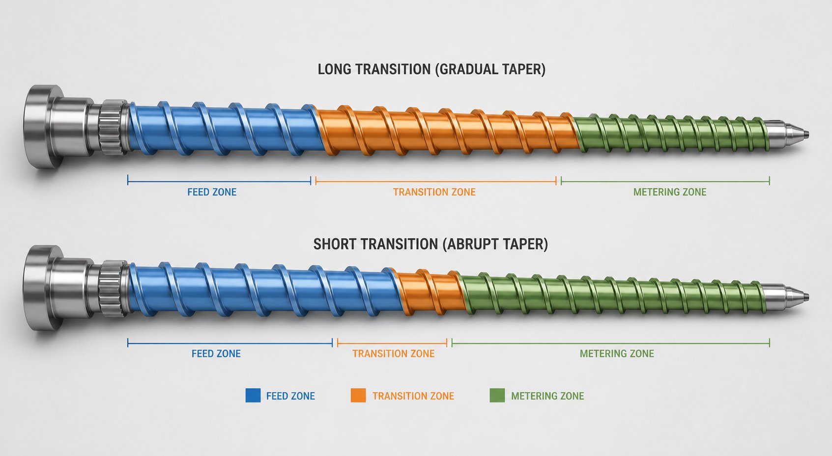
Two screws sitting side by side on a workbench can share the exact same compression ratio — say 3.0:1 — and still produce wildly different melt quality when installed in the same machine running the same resin. How? The answer lies not in the ratio itself, but in how the screw gets from its deep feed channel to its shallow metering channel. That journey — the transition zone — can happen gently over many flights or aggressively over just a few. The difference in injection molding screw design between those two approaches is enormous, and it rarely shows up in spec sheets.
Imagine hiking from sea level to 3,000 feet. You could take a long, winding trail with a gradual incline, or you could scramble straight up a cliff face. Both get you to the same elevation, but your body experiences something completely different along the way. Polymer in a screw channel faces the same choice, and its "body" — molecular structure, thermal tolerance, viscosity — determines which path it survives without damage.
Gradual Compression Profiles and Their Advantages
A gradual compression profile spreads the channel depth reduction over a long transition zone, typically spanning 5 to 8 times the screw diameter in length. The root diameter increases slowly from flight to flight, compressing the material in small, incremental steps rather than forcing a rapid squeeze. This design is characteristic of what many engineers consider best practice for the different zones of the injection molding screw when processing sensitive materials.
The benefits are rooted in thermodynamics and polymer behavior:
- Lower peak shear rates: Because the channel narrows slowly, the velocity gradient across the melt film stays moderate. Less frictional energy is dumped into the material at any single point, reducing the risk of localized hot spots that barrel thermocouples cannot detect.
- More uniform energy input: Heat from shear and barrel conduction distributes more evenly across the full transition length. Pellets have more time and more flight surfaces over which to absorb energy, which means fewer unmelts reach the metering zone.
- Reduced solid bed breakup: In a standard three-zone screw, the solid bed can fracture when compressed too aggressively, sending hard fragments into the melt pool. A gradual taper keeps the solid bed intact longer, allowing it to melt from the outside in — the way a controlled melting process should work.
- Better compatibility with thermally sensitive resins: Materials like PVC, POM, and certain TPU formulations degrade when shear energy spikes. A long, gentle transition keeps temperatures within the safe processing window while still achieving full compression.
The trade-off? A gradual profile requires a longer overall screw — or dedicates a larger proportion of the existing screw length to the transition zone, leaving less room for feed and metering sections. On shorter L/D screws, fitting a gradual transition can mean compromising feed zone length (reducing solids conveying capacity) or metering zone length (reducing melt pumping consistency). That engineering tension is why injection molding screw design always involves balancing zone lengths against one another, not just optimizing one zone in isolation.
Abrupt Compression Designs and When They Apply
An abrupt compression profile takes the opposite approach: the channel depth drops sharply over a short transition zone, sometimes as brief as 2 to 3 screw diameters. The root diameter ramps up steeply, forcing rapid densification and intense shear over a compact section of the screw.
This sounds aggressive — because it is. But for certain resins, that intensity is exactly what the process needs. Thermally stable, easy-to-melt polymers like LDPE and general-purpose polystyrene can tolerate high shear rates without degrading. They benefit from the rapid compression because it accelerates the melting process, allowing more of the screw's flighted length to be devoted to the feed and metering zones. The result is often higher throughput and faster screw recovery times — a meaningful advantage in high-volume production.
Abrupt designs also suit situations where the screw's L/D ratio is short and there simply is not enough length for a gradual transition. Some older or smaller injection molding machines ship with 18:1 or 20:1 L/D screws, and cramming three full zones into that limited length forces a compressed transition by default. In these cases, the abrupt profile is less a deliberate design choice and more a geometric necessity.
The risks, however, are real. Running a shear-sensitive resin — PC, rigid PVC, certain bioplastics — through an abrupt transition can cause localized degradation invisible in bulk temperature readings but clearly visible as black specks, streaks, or reduced mechanical properties in the molded part. Solid bed breakup also becomes more likely, which sends unmelted fragments past the transition zone where they have little chance of fully melting before injection.
Comparing the Two Approaches
| Characteristic | Gradual Compression Profile | Abrupt Compression Profile |
|---|---|---|
| Transition Zone Length | 5–8 x screw diameter | 2–3 x screw diameter |
| Suitable Resin Types | Shear-sensitive, thermally sensitive (PVC, POM, PC, TPU, bioplastics) | Thermally stable, easy-to-melt (LDPE, GPPS, PP) |
| Melt Uniformity Tendency | High — even energy distribution reduces unmelts and hot spots | Moderate — rapid compression can leave unmelted fragments |
| Shear Heat Generation | Lower peak values, spread over longer length | Higher peak values, concentrated in short section |
| Risk of Resin Degradation | Low — gentle profile minimizes thermal spikes | Higher — localized overheating possible with sensitive materials |
| Solid Bed Stability | Good — gradual taper maintains bed integrity | Poor — aggressive compression can fracture solid bed |
| Throughput Potential | Moderate — longer transition consumes screw length | Higher — compact transition frees length for feed and metering |
| Best L/D Fit | 24:1 and above | 18:1 to 22:1 (or high-output applications) |
The critical insight here is that a compression ratio spec sheet tells you where the screw starts and where it ends — but not how it gets there. Two screws with identical 3.0:1 ratios can produce dramatically different melt quality, shear histories, and degradation risk depending on whether the transition is stretched over eight diameters or crammed into two. If you are troubleshooting melt quality issues and your compression ratio appears correct for your resin, the transition zone profile deserves a hard look before you change anything else.
That diagnostic logic — matching observable defects to their geometric root cause — becomes even more critical when something is clearly going wrong on the production floor. Knowing what specific symptoms point to a compression ratio mismatch, versus a transition zone mismatch, versus an entirely different problem, is the difference between fixing the real issue and chasing ghosts through your process settings.
What Goes Wrong With the Wrong Compression Ratio and How to Diagnose It
You have seen the resin-by-resin ratios. You understand how screw diameter, L/D, and transition zone profile all modify what that ratio actually does to the polymer. But here is where the rubber meets the road — or, more accurately, where the melt meets the mold. When the compression ratio is wrong for the material running through it, the machine does not flash a warning light. Instead, it speaks through defects, wear patterns, and process instabilities that masquerade as dozens of other problems. Knowing which symptoms point back to the screw geometry — rather than to temperatures, pressures, or mold issues — saves you from weeks of chasing settings that were never the real problem.
Symptoms of a Compression Ratio That Is Too High
An overly aggressive compression ratio forces too much shear energy into the polymer. The screw channel narrows more than the material needs, generating excessive frictional heat that barrel heaters cannot compensate for — because the heat is coming from inside the melt, not from the barrel wall. The results cascade through every part of the process.
Resin degradation and discoloration. This is often the first visible sign. You pull parts and notice brown or yellow streaks, especially in lighter-colored resins. Black specks appear — not from contamination, but from polymer that has been thermally cracked by shear energy exceeding the resin's processing window. With PVC, the degradation releases hydrochloric acid that corrodes metal surfaces. With nylon or POM, you may smell the characteristic odor of thermal decomposition before you see visible defects. As industry troubleshooting guides note, burn marks and dark discolorations are typically caused by excessive temperatures — and an oversized compression ratio is one of the most overlooked sources of that excess heat.
Inconsistent melt temperature. Your barrel zone controllers might read perfectly, yet shot-to-shot melt temperature varies by 10 to 20 degrees. The reason? Shear heating generated by an aggressive compression ratio is not uniform across the melt stream. The layer closest to the screw root and the layer near the barrel wall experience different shear rates, producing a melt with hot spots and cooler zones that your thermocouple, reading a single point, cannot resolve. This inconsistency shows up as dimensional variation, warpage, and unpredictable shrinkage in finished parts.
Excessive wear on screw flights and barrel wall. A compression ratio that is too high forces the polymer against metal surfaces under greater pressure than the geometry was designed for. Over thousands of hours, this accelerates abrasive wear on flight tips and the barrel bore — particularly with filled compounds. If your injection molding screw and barrel wear tolerances are closing faster than expected, an overly aggressive compression profile could be the culprit, not just the abrasive filler. Worn flight clearances then reduce the effective compression, creating a cascading problem where the screw's performance deteriorates progressively.
High torque demand during recovery. The drive motor works harder to rotate a screw that is over-compressing. You may notice elevated hydraulic pressure during recovery, longer recovery times at the same RPM, or motor faults on electric machines. In extreme cases, this puts mechanical stress on the screw shank and spline connection.
Damage at the injection molding screw tip. Excessive shear and pressure in the metering zone can stress the non-return valve assembly at the front of the screw. An overworked check ring seats under higher-than-intended pressures cycle after cycle, accelerating wear on the valve seat and ring — which eventually causes shot-size inconsistency as the valve fails to seal properly during injection.
Symptoms of a Compression Ratio That Is Too Low
If too-high compression is about excess energy, too-low compression is about deficit. The screw channel does not narrow enough to consolidate the solids bed, press material against the barrel wall, and generate sufficient shear heat. The polymer arrives at the metering zone partially unprepared — and the symptoms are just as damaging, though entirely different in character.
Unmelted particles in parts. This is the hallmark defect of under-compression. You crack open a part or inspect a transparent molding and find hard, unmelted pellet fragments embedded in the matrix. These "unmelts" create weak spots, surface blemishes, and inconsistent mechanical properties. They often cluster near the last areas of the cavity to fill, carried there by the melt front. Screw design references confirm that a compression ratio too low for the material fails to deliver enough energy to melt the material completely — the unmelted particles and reduced output are predictable consequences.
Air entrapment and splay. When the compression profile does not sufficiently compact the solids bed, air trapped between pellets in the feed zone rides along into the melt. Some of this air dissolves under metering pressure, then flashes back to gas phase during injection, producing splay marks — silver streaks on the part surface that look like moisture defects but persist even with bone-dry resin. In some cases, you see actual bubbles or voids within the part wall.
Inconsistent shot weight. A poorly compressed melt delivers inconsistent density to the metering zone from shot to shot. One cycle, the metering section fills completely and pumps a full shot. The next, partially melted material and air pockets create a lower effective melt volume, producing a lighter shot. This variation resists correction through process settings because the root cause is geometric, not parametric.
Poor color mixing and additive dispersion. Compression contributes to distributive mixing. When the ratio is too low, color concentrates, additives, and blended materials do not get the mechanical working they need to disperse uniformly. Parts show color streaking, uneven pigmentation, or localized property variations where stabilizers or impact modifiers failed to distribute.
Reduced mechanical properties. Even without visible unmelts, under-compressed melt tends to be less homogeneous at the molecular level. Poorly mixed melt fronts create weld lines with reduced strength. Air inclusions act as stress concentrators. Impact resistance, tensile strength, and elongation at break can all fall below datasheet values — a subtle but serious quality issue for structural or safety-critical parts.
A Diagnostic Checklist for Your Current Screw
If you are experiencing any of the symptoms above, resist the urge to immediately adjust process settings. Before changing barrel temperatures, back pressure, or screw speed, run through this systematic evaluation to determine whether the compression ratio itself is the underlying issue. You may need to know how to remove screw from injection molding machine safely to take the measurements in steps two and three — consult your machine manual for lockout/tagout and barrel retraction procedures specific to your equipment.
- Identify your resin family and specific grade. Check the material safety data sheet and the supplier's processing guide. Note whether the resin is semi-crystalline or amorphous, its recommended melt temperature range, and any thermal sensitivity warnings. This establishes your baseline.
- Determine your current screw's compression ratio from physical measurements. Pull the screw and measure channel depths in the feed and metering zones using the method described earlier in this article. If the screw shows significant wear, also note the condition of flight tips — worn flights mean the effective compression is lower than the measured geometry suggests. Record any observations relevant to injection molding screw and barrel repair needs, such as scoring, galling, or material buildup in the channels.
- Inspect the injection molding screw tip and non-return valve. While the screw is out, examine the check ring, valve seat, and tip for wear, cracking, or resin buildup. A worn or damaged tip assembly compounds compression ratio problems by allowing melt to leak backward during injection, making shot-to-shot variation worse regardless of the screw's geometric ratio.
- Cross-reference your measured ratio against the resin table. Compare your screw's compression ratio to the recommended range for your resin family from the table in the earlier section. Note whether your measured value falls within, above, or below the recommended range.
- Catalog the symptoms you observe. List every defect and process instability you are experiencing. Use the symptom descriptions above to categorize them as "too high" or "too low" indicators. If symptoms from both lists appear simultaneously, consider whether screw wear, a damaged non-return valve, or feedstock variability is muddying the picture.
- Evaluate whether process adjustments can compensate. Minor mismatches — a ratio only slightly outside the recommended range — can sometimes be managed through back pressure adjustments, screw speed changes, or barrel temperature profiles. But if the ratio is significantly off, or if injection molding screw cleaning and process optimization have not resolved persistent defects, the screw geometry itself is the problem, and process settings cannot fully compensate for a fundamental design mismatch.
- Determine whether a screw change is warranted. If the ratio falls outside the recommended range for your resin and the symptom pattern matches, you are looking at a screw replacement decision — not a process tuning exercise. Document your measurements, resin data, symptom log, and machine specifications. This package is exactly what a screw manufacturer needs to recommend or design a properly matched replacement.
Injection molding screw repair can address wear-related issues — rebuilding flight tips, re-nitriding surfaces, or replacing damaged check rings — but it cannot change a screw's compression ratio. If the fundamental geometry is wrong for your material, refurbishment restores a screw to its original mismatch. What you need instead is a screw designed for your specific resin, machine, and application. For processors who reach step seven and confirm that their current screw geometry is the root cause, NANHAIYA's injection molding screw barrel solutions offer custom screw barrel manufacturing matched to specific material requirements and machine sizes — a practical path from diagnosis to resolution without repeating the same mismatch.
This diagnostic framework handles the conventional resins most shops run daily. But an increasing share of production involves materials that push beyond conventional screw design assumptions — glass-filled compounds, recycled feedstocks with unpredictable bulk density, and bioplastics with unique thermal profiles. These materials create compression ratio challenges that a standard general-purpose screw was never engineered to solve.
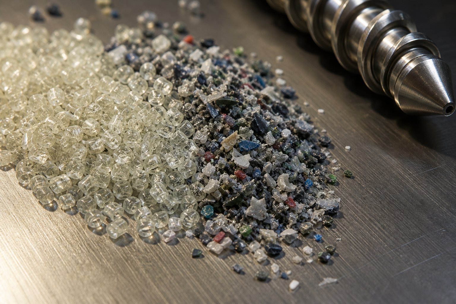
Compression Ratio for Filled Plastics, Recycled Resins, and Modern Materials
A general-purpose screw with a 2.5:1 compression ratio might run unfilled ABS all day without a hiccup. Load that same resin with 30% glass fiber, and everything changes — bulk density shifts, flow behavior stiffens, and abrasive particles start grinding away at flight surfaces with every rotation. Swap the virgin pellets for post-consumer regrind, and the feedstock arriving at the hopper varies from batch to batch in particle size, moisture content, and contamination level. Try running a PHA bioplastic, and you discover a material so thermally fragile that the compression profile needs to be rethought from scratch.
These are not niche scenarios. Filled compounds, recycled resins, and bio-based polymers represent some of the fastest-growing material categories in injection molding. Yet the screws inside most machines were designed decades ago for neat, virgin thermoplastics with predictable properties. The mismatch between modern materials and legacy screw geometry is a growing source of defects, excessive wear, and lost productivity that standard troubleshooting checklists rarely address.
Compression Ratio Adjustments for Glass-Filled and Mineral-Filled Compounds
Adding fillers to a polymer changes three things that directly affect how compression ratio performs: bulk density, melt rheology, and abrasiveness. Each one pulls the screw design in a different direction, and getting the balance right is more nuanced than simply bumping the ratio up or down.
Bulk density effects. Glass fibers and mineral fillers like calcium carbonate, talc, or wollastonite increase the compound's overall density. A 30% glass-filled nylon, for example, has a higher solid bulk density than neat nylon, which means the feed zone channel does not need to be as deep to capture the same mass of material per flight. The density gap between solid feedstock and melt narrows compared to unfilled resin, which often means the compression ratio can be slightly lower than what the base polymer alone would demand — perhaps 3.0:1 to 3.5:1 for glass-filled PA instead of the 3.5:1 to 4.0:1 range typical for neat nylon.
Flow behavior changes. Fillers increase melt viscosity and reduce the resin's ability to flow freely under shear. A highly filled compound resists the compacting action of the compression zone more aggressively than its unfilled counterpart. Too much compression forces this stiff melt through a narrow channel under extreme pressure, generating localized shear heating that can degrade the polymer matrix surrounding the fillers. As screw optimization research notes, glass-fiber or mineral-filled plastics need reinforced mixing zones designed to handle the altered rheology without over-shearing the base resin.
Fiber integrity under compression. This is the factor most processors overlook. Glass fibers entering the feed zone as 3-4 mm chopped strands can exit the metering zone as fragments barely 200 microns long if the compression ratio is too aggressive. Every time the narrowing channel forces fiber-laden melt through a tighter gap, fibers break. Excessive compression ratios — or abrupt transition zones — fracture fibers more than necessary, directly reducing the mechanical reinforcement the filler was supposed to provide. For structural parts where fiber length retention matters, a moderate compression ratio paired with a gradual transition profile preserves more fiber integrity than a high-ratio, abrupt-transition design.
Wear considerations. Glass fibers are abrasive. Mineral fillers are abrasive. Running these materials through any screw accelerates wear, but an overly high compression ratio intensifies the problem by pressing abrasive particles against flight tips and barrel walls under greater force. This is where injection molding machine screw barrel material hardness becomes a critical specification — bimetallic barrels and tool-steel or tungsten-carbide-coated screws are not optional luxuries for filled compounds; they are baseline requirements. Choosing the right compression ratio reduces the wear rate by limiting unnecessary pressure on metal surfaces, but it cannot eliminate wear entirely. The screw and barrel metallurgy must match the filler's abrasiveness.
Recycled Resins, Bioplastics, and Variable Feedstock Challenges
If filled compounds challenge screw design through changed material properties, recycled resins challenge it through unpredictability. And bioplastics challenge it through narrow thermal windows that leave almost no margin for error.
Recycled resin variability. Post-consumer and post-industrial regrind arrives with inconsistent particle sizes — a mix of flakes, chunks, fines, and occasional whole pellets. That variability directly affects bulk density in the feed zone, which means the same geometric compression ratio produces different effective compression from one batch to the next. A hopper full of uniform pellets packs predictably; a hopper of mixed regrind leaves larger air gaps, feeds erratically, and can bridge or starve individual flights. Moisture content fluctuates too, adding another variable that changes how the material responds to shear and heat. Fixed compression ratio screws designed for virgin feedstock often under-compress one regrind batch and over-compress the next, producing the kind of shot-to-shot inconsistency that drives quality teams to distraction.
Processors running high percentages of recycled content sometimes benefit from a slightly higher compression ratio than the virgin material would require — enough to accommodate the worst-case bulk density scenario — combined with higher back pressure during recovery to supplement the geometric compression. But this is a compromise, not a solution. The real answer for high-volume recycled-content operations is often a screw specifically designed for the expected feedstock variability, with a compression profile that handles a range of bulk densities without tipping into degradation at the dense end or leaving unmelts at the light end.
Bioplastics: PLA, PHA, and blends. Bioplastics bring their own compression ratio puzzle. PLA is semi-crystalline but has a narrow processing window — it transitions from solid to low-viscosity melt relatively quickly, and prolonged exposure to melt temperatures degrades molecular weight. Standard compression ratios in the 2.5:1 to 3.0:1 range generally work, but the transition zone design matters more than the ratio number itself. Gradual compression profiles help prevent the localized shear spikes that push PLA past its thermal limits.
PHA is even more demanding. Processing guidelines from Danimer Scientific describe PHA as resembling PVC in its tendency to cause temperature overruns in the compression zone due to its shear-sensitive nature. Excess heat above 400 degrees Fahrenheit causes rapid degradation, and even prolonged exposure at 350 degrees Fahrenheit begins breaking the polymer down. The recommendation is clear: low compression screws with standard general-purpose designs, screw speeds set as slow as possible while remaining in cycle, and barrel temperatures held in a tight 320-350 degree Fahrenheit window. A high compression ratio that works beautifully for polyethylene would destroy PHA within minutes.
Engineering compounds and specialty blends. High-performance materials like PEEK, PPS, LCP, and heavily modified engineering blends each bring unique compression requirements driven by their specific crystallinity, viscosity, and thermal profiles. Many of these resins are processed in relatively small volumes on machines that also run commodity plastics, which means the installed general-purpose screw is almost certainly wrong for the specialty material. The compression ratio mismatch might be tolerable for short runs, but it shows up in reduced mechanical properties, surface quality issues, and accelerated screw wear that erode any cost advantage the processor hoped to gain.
Here is a quick-reference summary of how these modern material categories interact with compression ratio selection:
- Glass-fiber-filled compounds (15-50% loading): Moderate compression ratios (2.5:1 to 3.5:1, depending on base resin and fill level). Gradual transitions preserve fiber length. Bimetallic injection molding screws and barrels are essential to resist abrasive wear.
- Mineral-filled compounds (talc, CaCO3, mica): Similar ratio adjustments as glass-filled, but with less concern about fiber breakage. Focus shifts to wear resistance and melt homogeneity, as mineral particles can settle or agglomerate without adequate mixing.
- Post-consumer recycled (PCR) resins: Slightly higher compression ratios than virgin equivalent to handle variable bulk density. Supplemental back pressure helps compensate for feed inconsistency. Screws should tolerate occasional contaminants without catastrophic wear.
- Post-industrial regrind: More predictable than PCR but still variable in particle geometry. Compression ratio close to virgin specification usually works if particle size is reasonably consistent. Blending with virgin pellets stabilizes feed behavior.
- PLA: Moderate compression (2.5:1 to 3.0:1) with gradual transition zone. Minimize residence time at melt temperature. Standard general-purpose screw geometry generally adequate with process control attention.
- PHA and PHA/PLA blends: Low compression ratios (2.0:1 to 2.5:1) with gentle transition profiles. Extremely shear-sensitive — treat like PVC in terms of screw geometry conservatism. Slow screw speeds mandatory.
- High-performance engineering polymers (PEEK, PPS, LCP): Resin-specific compression ratios that vary widely. Consult material supplier data. High processing temperatures demand corrosion resistant screws for PVC injection molding-grade metallurgy or better, since some of these resins release corrosive byproducts at elevated temperatures.
Making the Investment Decision
Faced with this landscape, the practical question becomes straightforward: does your current screw earn its place in the barrel, or is it costing you more in scrap, rework, wear, and lost productivity than a properly matched replacement would cost?
For shops running a single commodity resin on a dedicated machine, the general-purpose screw that came with the machine might be close enough. But the moment your material mix includes filled compounds, recycled content, bioplastics, or engineering-grade polymers — and for most modern molding operations, it does — the screw geometry becomes a variable you cannot afford to leave to chance.
A purpose-built screw matched to your material, machine size, and production requirements is not a luxury purchase. It is a precision tool that pays for itself through reduced scrap rates, lower energy consumption, extended injection molding barrel and screw service life, and consistent part quality that keeps your customers from calling with complaints. The cost of the wrong screw is not the purchase price — it is every defective part, every unplanned maintenance shutdown, and every hour of process tweaking that never quite fixes the root cause.
For processors who have worked through the diagnostic checklist in the previous section and confirmed that their screw geometry is mismatched to their current material demands — especially those running filled, recycled, or specialty resins — NANHAIYA's custom injection molding screw barrel manufacturing serves injection molding factories, machine rebuilders, and maintenance engineers seeking replacement plasticizing components engineered for specific material requirements and machine sizes. Rather than adapting your process to a screw that was never designed for your material, the more effective path is adapting the injection molding screw and barrel to the material you actually run.
Frequently Asked Questions About Compression Ratio for Injection Molding Screws
1. What is a good compression ratio for a general purpose injection molding screw?
A general purpose injection molding screw typically uses a compression ratio between 2.5:1 and 3.0:1. This range handles a broad selection of commodity resins like PS, ABS, and some polyolefins reasonably well, but it is rarely optimal for any single polymer. Semi-crystalline resins such as nylon and PE generally perform better at 3.0:1 to 4.0:1, while thermally sensitive materials like rigid PVC need ratios as low as 1.5:1 to 2.5:1. If you run multiple materials on one machine, a general purpose ratio is a starting compromise — but matching the screw to your primary resin family almost always improves melt quality and reduces scrap.
2. How do you calculate the compression ratio of an injection molding screw?
Measure the channel depth in the feed zone and the channel depth in the metering zone, then divide the feed depth by the metering depth. Channel depth is found by subtracting the root diameter from the outer flight diameter and dividing by two. For example, a screw with a 50 mm outer diameter, a 30 mm feed root diameter, and a 42 mm metering root diameter yields feed depth of 10 mm and metering depth of 4 mm, giving a 2.5:1 ratio. Always measure in the constant-depth portions of the feed and metering zones — never in the tapered transition zone — and account for any flight wear that could skew the result.
3. What happens if the compression ratio is too high for my resin?
An excessively high compression ratio generates too much shear heat inside the melt, leading to resin degradation, discoloration, black specks, and inconsistent melt temperatures that barrel heaters cannot correct. You may also notice accelerated wear on screw flights and barrel walls, higher torque demand during recovery, and premature failure of the non-return valve at the screw tip. Thermally sensitive resins like PVC and POM are especially vulnerable — the excess shear energy can trigger chemical decomposition. If you observe these symptoms and your ratio exceeds the recommended range for your material, replacing the screw with a properly matched geometry is more effective than adjusting process parameters alone.
4. Does compression ratio differ between injection molding screws and extrusion screws?
Yes. Although both screw types use the same basic formula, injection molding screws operate in a reciprocating mode — rotating to plasticize, then sliding forward to inject. This reciprocating action changes the effective flighted length engaged during each cycle, and adjustable back pressure adds a compression mechanism that extrusion screws lack. As a result, injection molding screws often use slightly more conservative compression ratios than extrusion screws for the same polymer. Applying extrusion screw data directly to an injection molding application can lead to suboptimal melt quality because the dynamic operating conditions are fundamentally different.
5. What compression ratio should I use for glass-filled or recycled plastics?
Glass-filled compounds generally perform well at moderate ratios — typically 2.5:1 to 3.5:1 depending on base resin and fill percentage — because the filler raises bulk density and narrows the solid-to-melt density gap. Gradual transition zones help preserve fiber length. Recycled resins with inconsistent particle sizes and bulk densities may need slightly higher ratios than their virgin equivalents to handle worst-case feed conditions, supplemented by increased back pressure. In both cases, screw and barrel metallurgy matters as much as geometry: bimetallic barrels and hardened screws resist the abrasive wear that filled and contaminated feedstocks accelerate. Custom screw barrel solutions, such as those from NANHAIYA at nhyscrews.com, can be engineered to match specific filler types, loading levels, and machine sizes.
Written by
Nanhaiya Technical Team
Zhoushan Nanhaiya Plastic Machinery Co., Ltd.
The Nanhaiya technical team supports screw and barrel manufacturing projects through application review, technical communication, custom manufacturing coordination, and production and quality control.
Discuss Your Application
Related Articles
More insights on screw barrel technology and plastics processing.

What Nobody Tells You About Screw Barrel For Plastic Machine Design
Oct 10, 2026
Learn how screw barrel for plastic machine design affects melt quality, throughput, and wear life. Covers geometry, resin matching, troubleshooting, and sourcing.
Read Article
Single Screw Extruder for Sheet: Stop Guessing, Start Specifying
Oct 9, 2026
Learn how to specify a single screw extruder for sheet production. Covers screw geometry, resin-specific processing, troubleshooting, and maintenance best practices.
Read Article
PE Pipe Extruder Machine: What Datasheets Won't Tell You
Oct 9, 2026
Learn how a PE pipe extruder machine works, key specs explained, material grade selection, maintenance tips, and buyer guidance beyond the datasheet.
Read ArticleLooking for something else?
Search by material, symptom or product and jump straight to the relevant page.
These are navigation suggestions based on keyword matching — not a quotation, not a delivery commitment, and not a substitute for engineering review. Final specification is confirmed by our engineers against your drawings and processed material.
Need help with screw barrel selection?
Share your machine model, processed material and application. Our team can help with pricing and technical support.