

Twin Screw Extruder Fundamentals and Why Rotation Direction Matters
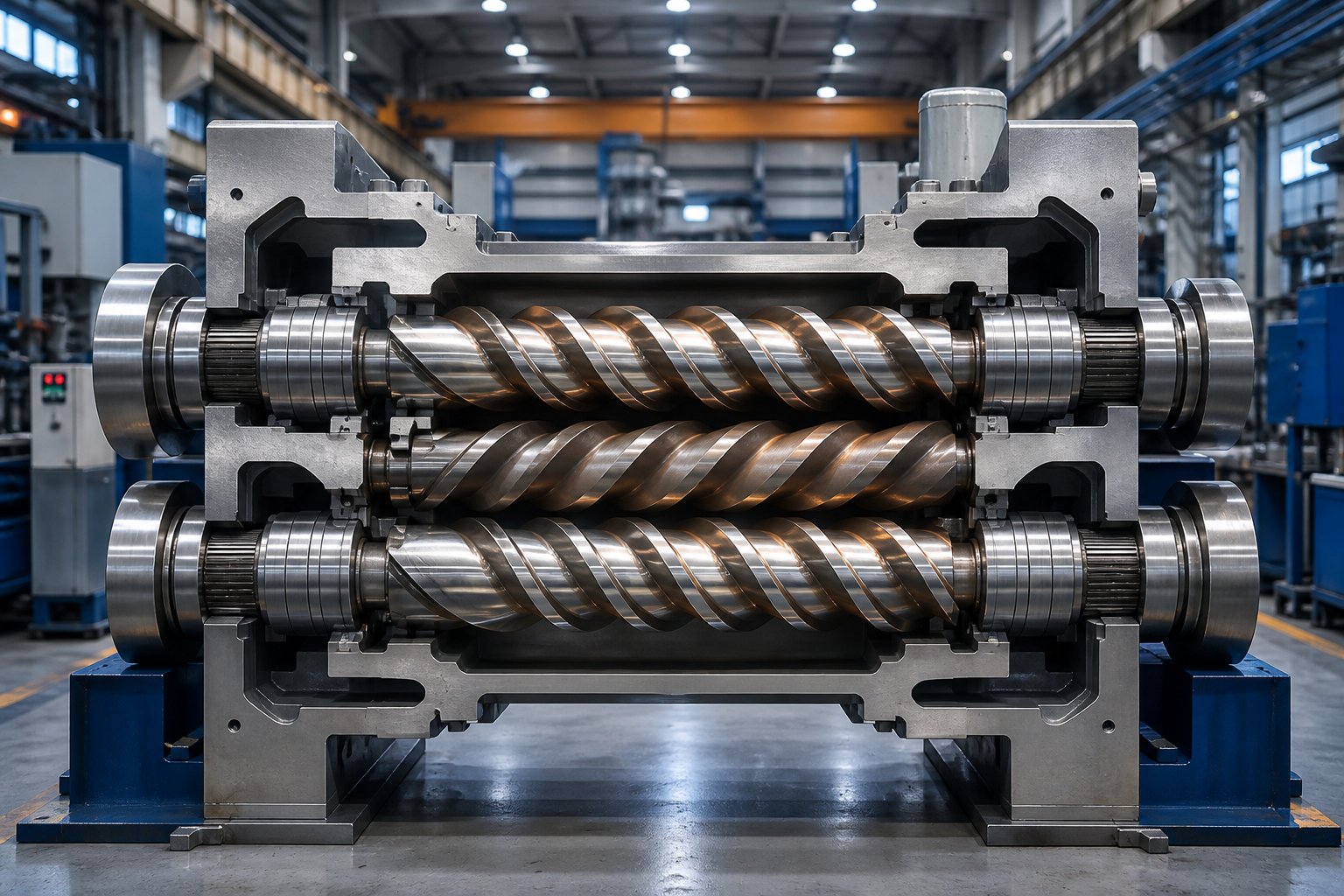
Imagine two screws spinning side by side inside a heated barrel, grabbing raw polymer, and transforming it into a uniform, precisely compounded melt. That single image captures the essence of twin screw extrusion — and yet the direction those screws rotate creates two fundamentally different machines. If you have ever debated whether a co rotating or counter rotating twin screw extruder is the right fit for your line, you already know the stakes: the wrong choice burns energy, accelerates wear, and puts product quality at risk.
What Are Twin Screw Extruders and Why Do They Matter
A twin screw extruder is a processing machine that uses two parallel, intermeshed screws rotating inside a heated barrel to melt, mix, compound, and shape polymers and other materials. It is the backbone of modern compounding, masterbatch production, reactive extrusion, and pelletizing operations.
Unlike a single screw extruder, which relies on one rotating screw for conveying and melting, the twin screw extruder generates complex flow fields between its two screws. This intermeshing action produces high shear forces, thorough homogenization, and superior dispersion of additives and fillers. The result is a more versatile platform capable of handling everything from highly viscous engineering plastics to heat-sensitive PVC formulations.
Why Rotation Direction Changes Everything
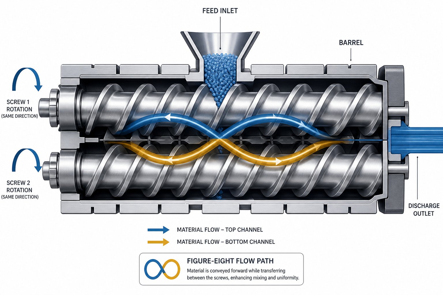
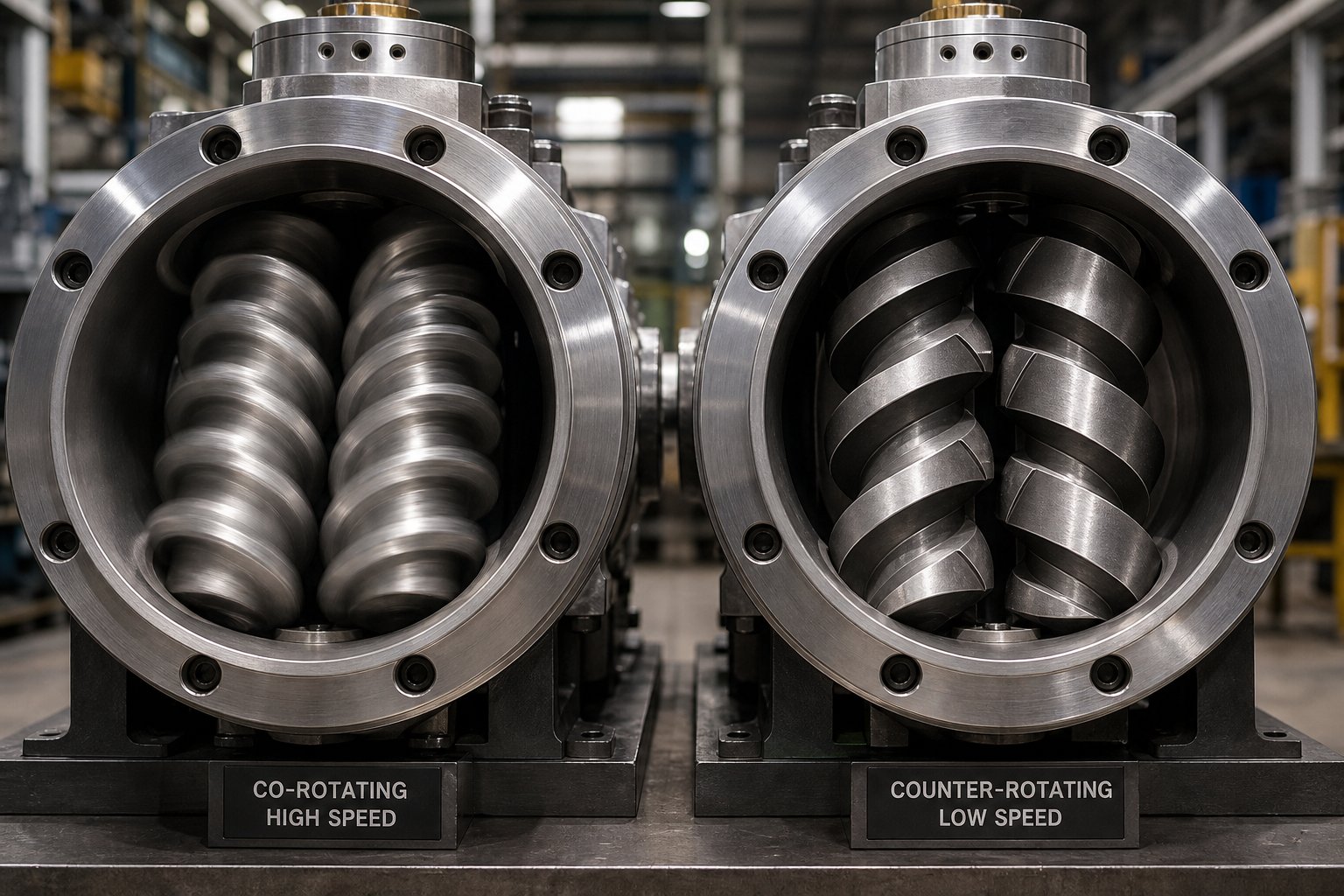
Here is where the conversation splits into two distinct engineering paths. In a co rotating twin screw extruder, both screws turn in the same direction. Material follows a figure-eight flow path between the screws, and a self-wiping geometry keeps dead spots to a minimum. In a counter rotating twin screw extruder, the screws turn in opposite directions, drawing material into the nip region and generating high pressure through a calendering-like compression.
That single difference — same direction versus opposite direction — reshapes nearly every performance variable you care about:
- Shear rate and mixing intensity
- Pressure generation capability
- Residence time distribution
- Thermal load on the polymer
- Wear patterns and maintenance cycles
Choosing between a co rotating and counter rotating twin screw extruder is not about picking the "better" machine. It is about matching flow mechanics, shear profiles, and pressure characteristics to the specific material and process sitting on your production floor. This guide breaks down both configurations with the technical depth engineers need — no brand bias, no oversimplification — so you can stop guessing and start specifying with confidence.
The clearest way to build that confidence is to understand exactly how each screw rotation pattern moves and mixes material at the mechanical level.
How Co-Rotating Twin Screw Extruders Work
Picture both screws spinning in the same direction — clockwise, for instance — with their flights tightly intermeshed like two helical gears. As material enters the barrel, each screw's flight drags it forward along the barrel wall, then hands it off to the neighboring screw at the intermeshing zone. The result is a continuous figure-eight flow path that forces the polymer through alternating high-shear and low-pressure regions. This drag-flow-dominated conveying mechanism is what gives the co rotating twin screw extruder its distinctive processing character.
How Co-Rotating Screws Move and Mix Material
Think of the cross-section between one screw flight and the barrel wall as an open C-shaped chamber. Because both twin screws rotate in the same direction, the flight tip of one screw closely sweeps the root of the other. That tight clearance creates a self-wiping action — material cannot stagnate on the screw surface or barrel wall, because the opposing flight continuously scrapes it away and pushes it forward.
Why does that matter? Dead spots are where polymers degrade. When material sits too long in one place, it overheats, discolors, crosslinks, or chars. Self-wiping virtually eliminates those pockets, keeping the melt fresh and thermally uniform from feed throat to die. As Technovel's technical overview explains, this wiping effect suppresses gelation and thermal degradation while maintaining stable heat transfer efficiency inside the barrel.
The figure-eight transfer path also delivers a powerful dual mixing action. Each time the material crosses the intermeshing region, it experiences intense dispersive mixing — high shear stress that breaks down agglomerates, splits filler clusters, and reduces droplet size in polymer blends. Between those crossover points, the material redistributes across the open channel, achieving distributive mixing that spreads every component evenly throughout the melt. Few other mechanical systems deliver both mixing modes simultaneously and continuously.
Speed capability amplifies these advantages. Modern co rotating twin screw extruder platforms feature segmented screw elements assembled on high-torque splined shafts, with screw speeds available to 1200+ RPM. Higher RPM intensifies shear and shortens residence time, making these machines especially effective for energy-intensive compounding and reactive processes.
Ideal Processing Characteristics of Co-Rotating Extruders
The combination of self-wiping geometry, drag-flow conveying, and high-speed capability produces a set of processing characteristics that no other single platform replicates:
- High-filler compounding — uniform dispersion of calcium carbonate, glass fiber, talc, and carbon black at loading levels that would choke a single screw machine
- Color masterbatch production — intense dispersive mixing ensures pigment particles break down to primary size, eliminating specks and streaks in downstream molded parts
- Polymer blending and alloying — the figure-eight flow pattern distributes immiscible phases into fine, stable morphologies critical for engineering-grade blends
- Reactive extrusion — narrow residence time distribution (RTD) keeps every molecule in the barrel for nearly the same duration, promoting consistent reaction conversion and minimizing side reactions
- Devolatilization — starve-fed operation creates partially filled screw channels that expose large melt surface areas under vacuum vents, stripping moisture, residual monomers, and solvents with high efficiency
- Recycling of contaminated feedstock — self-cleaning action handles inconsistent, contaminated post-consumer streams without frequent shutdowns for purging
Because the twin-screw extruder operates in a starve-fed mode, the feed rate is decoupled from screw speed. You can dial RPM up or down to fine-tune shear intensity without changing throughput — or raise the feed rate independently to increase output. That operational flexibility, combined with modular screw elements that can be rearranged to alter mixing zone intensity and length, makes the co-rotating intermeshing platform the most versatile twin-screw extruder configuration available.
Versatility, however, is only one side of the equation. Some processes demand qualities the co-rotating design does not prioritize — especially high-pressure, low-shear conveying for thermally sensitive materials. That is exactly where counter-rotating technology carves out its own engineering advantage.
How Counter-Rotating Twin Screw Extruders Work
Counter-rotating twin-screw extruders have long lived in the shadow of their co-rotating cousins. Industry literature tends to treat them as a niche afterthought — a machine you use for PVC and little else. That reputation is misleading. As research from Demirci et al. points out, counter-rotating intermeshing twin screw extruders have received "20 to 50 times" less R&D investment than co-rotating platforms — a gap driven more by historical circumstances and industry politics than by inherent engineering limitations. The result is a technology that remains poorly understood even by experienced processors.
So what actually happens when two screws turn in opposite directions? The answer centers on a completely different material transport mechanism — one built around enclosed chambers, positive displacement, and a calendering squeeze that generates pressure without brute-force screw speed.
Positive Displacement and Calendering Flow Mechanics
When both screws rotate in opposite directions, the intermeshing flights of one screw seal off the channel of the other. Instead of the open C-shaped chambers found in co-rotating designs, the extruder twin screw geometry creates closed C-shaped chambers that trap discrete pockets of material and push them axially along the barrel. Imagine a series of sealed compartments traveling from feed end to die — each one carrying its charge forward in a nearly plug-flow fashion. That is positive-displacement conveying, and it is fundamentally different from the drag-flow mechanism driving co-rotating machines.
This closed-chamber architecture delivers two practical advantages you will notice immediately on the production floor:
- High pressure at low speed — because forward movement depends on mechanical displacement rather than frictional drag, the extruder builds substantial die pressure without requiring high RPM
- Low frictional heating — less screw speed means less viscous dissipation, which translates directly into lower melt temperatures for heat-sensitive polymers
The intermeshing region itself introduces another critical flow phenomenon. As the two screws rotate outward (the most common configuration), material is drawn into the narrowing gap between the core of one screw and the flight tip of the other. This nip zone squeezes the melt in a manner closely analogous to a pair of calender rolls compressing a sheet of material. The calendering effect produces compressive and elongational deformation rather than the intense simple shear found in co-rotating machines. Material undergoes repeated compression cycles as it passes each flight, dispersing additives under relatively gentle conditions.
There is, however, a mechanical cost to this calendering action. The squeeze flow in the nip region generates large separating forces that push each screw outward toward the barrel wall. Experimental measurements on a 55 mm counter-rotating extruder showed resultant forces exceeding one metric ton in the metering zone alone — forces concentrated at roughly 30 degrees from the vertical axis. Those separating forces are the primary reason counter-rotating twin-screw extruders run at significantly lower RPM than co-rotating platforms. As screw speed increases, calender pressure rises sharply, and at high enough speeds the melt film between screw and barrel can fail catastrophically. Large-diameter closely intermeshing counter-rotating machines are typically limited to fewer than 50 RPM, while even moderate-size production units stay below 150 RPM to manage these forces safely.
The trade-off is clear: you get excellent pressure generation and minimal thermal degradation, but you sacrifice throughput rate and mixing intensity relative to a high-speed co-rotating line.
HSEI vs LSLF Counter-Rotating Classifications
Here is where many engineers make a critical mistake — treating "counter-rotating" as a single technology. It is not. The counter-rotating family splits into two distinct subtypes that serve very different processing objectives, and confusing the two leads to mismatched equipment and wasted capital.
The HSEI (High-Speed Energy Input) classification describes twin-screw extruders — both co-rotating and counter-rotating — designed for energy-intensive mixing at moderate to high screw speeds. Counter-rotating HSEI machines operate at speeds well above the traditional PVC range, using larger calender gaps and sometimes non-intermeshing geometries to avoid destructive separating forces. They target specialty compounding applications where a counter-rotating flow pattern offers advantages for specific material systems.
The LSLF (Low-Speed Late Fusion) classification, by contrast, describes the classic closely intermeshing counter-rotating extruder built specifically for materials like rigid PVC. "Late fusion" refers to the processing philosophy: the PVC powder formulation is conveyed and compressed at low shear for much of the barrel length, fusing into a homogeneous melt only in the final zones before the die. This deliberate delay prevents premature gelation and thermal decomposition — problems that would be unavoidable if the same material were exposed to the high shear fields of a co-rotating or HSEI machine.
LSLF counter-rotating extruders typically run at very low speeds — often below 50 RPM — and rely on the positive-displacement mechanism to generate all the pressure needed for downstream die forming. Many of these machines use a conical twin screw extruder geometry, where the screws taper from a large diameter at the feed end to a smaller diameter at the discharge. The conical design increases the available cross-section for feeding bulky PVC powder while progressively compressing the material as it approaches the die, all within a compact machine footprint.
The table below maps the key differences between HSEI and LSLF counter-rotating subtypes:
| Parameter | HSEI Counter-Rotating | LSLF Counter-Rotating |
|---|---|---|
| Screw Speed Range | Moderate to high (up to several hundred RPM) | Very low (typically below 50 RPM) |
| Primary Application | Specialty compounding, energy-intensive mixing | Rigid PVC pipes, profiles, sheet, and cable duct extrusion |
| Shear Level | Moderate — higher than LSLF but lower than co-rotating HSEI | Low — deliberately minimized to prevent thermal degradation |
| Material Suitability | Materials requiring counter-rotating flow characteristics at elevated throughput | Heat-sensitive polymers with poor melt flow, especially rigid PVC formulations |
| Intermeshing Degree | May use larger gaps or non-intermeshing geometry | Closely intermeshing for maximum positive displacement |
| Typical Screw Geometry | Parallel | Parallel or conical (tapered) |
| Fusion Strategy | Early fusion through energy input | Late fusion — material remains partially unfused through most of the barrel |
Understanding this split matters because it directly shapes which machine you specify. A processor extruding rigid PVC window profiles needs an LSLF conical twin screw extruder operating at 30 to 40 RPM with tight intermeshing and maximum positive displacement. A compounder blending specialty additives into a thermoplastic elastomer at moderate throughput might choose a counter-rotating HSEI platform for its unique flow characteristics. Lumping both machines under a single "counter-rotating" label obscures engineering differences that determine success or failure on the production floor.
With both co-rotating and counter-rotating operating principles now on the table, the natural question becomes: how do their measurable performance parameters actually compare when placed side by side?
Side-by-Side Technical Comparison of Key Performance Parameters
You have the operating principles. You understand the flow mechanics. But when it comes time to specify a double screw extruder machine for a real production line, what you actually need are numbers — or at the very least, clear relative rankings across every parameter that affects throughput, product quality, and operating cost. The table below puts co-rotating and counter-rotating configurations on the same page, parameter by parameter, so you can evaluate them against your specific process requirements rather than relying on generalized industry advice.
Performance Parameter Comparison Table
This comparison draws on CFD simulation data and published engineering benchmarks to capture the measurable differences between the two configurations. Where exact values depend on machine size and formulation, relative performance descriptors are used.
| Performance Parameter | Co-Rotating Intermeshing | Counter-Rotating Intermeshing |
|---|---|---|
| Screw Speed Range | High — modern HSEI platforms reach 1200+ RPM | Low to moderate — LSLF types typically below 50 RPM; HSEI counter-rotating up to several hundred RPM |
| Shear Rate | High — amplified by screw speed and kneading block geometry; shear is broadly distributed across the intermeshing zone | Lower overall, but with localized shear spikes caused by leakage flow through tight intermeshing clearances |
| Throughput Capacity | Significantly higher — starve-fed operation with independent screw speed and feed rate control enables high volumetric output | Lower — positive displacement conveying limits throughput to the volumetric capacity of the closed C-chambers at operating RPM |
| Pressure Generation | Moderate — relies on discharge screw elements to build die pressure; less efficient at pure pressure generation | High — positive displacement and calendering mechanics generate substantial pressure without high screw speed |
| Dispersive Mixing | Strong — simultaneous shear and elongational fields in kneading zones break agglomerates effectively | Stronger peak shear stress — CFD data shows a higher probability of particles experiencing elevated maximum shear levels |
| Distributive Mixing | Superior — the figure-eight flow path continuously redistributes material between screws, producing high spatial uniformity | Lower — most material remains enclosed in C-chambers with limited cross-channel exchange |
| Residence Time Distribution (RTD) | Narrow and left-shifted — tracer particles exit faster with a tighter spread (span of approximately 53.8 s in comparative CFD tests) | Broader and right-shifted — longer mean residence time with wider spread (span of approximately 58.3 s under identical test conditions) |
| Self-Wiping Capability | Excellent — flight tips continuously sweep the opposing screw root, eliminating dead zones and stagnation | Limited — closed chamber geometry reduces wiping action; material can accumulate in nip regions |
| Torque Characteristics | High torque demand at high RPM — segmented shafts and high-torque gearboxes required for energy-intensive compounding | Lower torque demand — positive displacement reduces the rotational force needed to convey and pressurize material |
| Energy Consumption Profile | Higher specific energy for mixing-intensive operations — motor energy input drives shear and dispersive action | Lower specific energy for pressure-dependent operations — mechanical displacement replaces frictional energy input |
| Thermal Management | Higher viscous dissipation generates more shear heating — requires active barrel cooling and careful temperature zoning | Lower shear heating — melt temperature stays closer to set-point, critical for thermally sensitive materials like rigid PVC |
What the Numbers Mean for Your Process
A table full of parameters only becomes useful when you connect it to a real processing objective. Here is how to read the data above through the lens of practical decision-making.
If your primary goal is mixing intensity and throughput — compounding filled polymers, producing color masterbatch, or running reactive extrusion — the co-rotating column is where your twin-screw extruder machine should land. The combination of high screw speed, narrow RTD, and superior distributive mixing means every kilogram of output receives consistent, thorough homogenization. Starve-fed operation lets you decouple feed rate from RPM, giving you an independent lever to tune shear intensity without sacrificing production volume. For energy-intensive processes, the higher specific energy input is not waste — it is the mechanism doing the actual work of breaking filler agglomerates and driving chemical reactions to completion.
If your primary goal is pressure generation with minimal thermal load — extruding rigid PVC profiles, forming calendered sheet, or pushing melt through restrictive dies — the counter-rotating column tells a very different story. Positive displacement delivers the die pressure you need without running the screws at speeds that would overheat the polymer. The broader residence time distribution, often viewed as a disadvantage in compounding, actually benefits PVC processing and similar applications where extended time under gentle conditions promotes gradual, controlled gelation rather than abrupt, shear-driven fusion.
Energy consumption differences reinforce this split. Counter-rotating screw extruders generally consume less energy per kilogram of output in pressure-dependent processes because forward conveying relies on mechanical displacement rather than frictional drag. Co-rotating machines, by contrast, are more energy-efficient when the process objective is mixing — the motor energy converts directly into dispersive and distributive work rather than being lost as unproductive heat.
One result from CFD-validated mechanical testing illustrates the downstream quality implications of this split: samples produced on a co-rotating extruder showed slightly higher tensile strength and elongation at break, while counter-rotating samples exhibited marginally higher impact energy absorption and impact strength. The difference traces directly back to mixing mechanics — co-rotating's distributive uniformity favors tensile properties, while counter-rotating's elongational deformation and broader residence time produce more extensive chain relaxation, which benefits impact performance.
These are not abstract distinctions. They determine whether a window profile survives an impact test, whether a masterbatch disperses cleanly in a film line, and whether a reactive compound achieves target conversion. The comparison table above gives you the framework — but translating it into a real specification also requires understanding the sub-classifications within each family, starting with the often-overlooked distinction between intermeshing and non-intermeshing screw geometries.
Intermeshing vs Non-Intermeshing and Modular Screw Design
Most discussions about co rotating and counter rotating twin screw extruders stop at rotation direction. That leaves half the story untold. Within each rotation family, a second classification axis determines how tightly the screws engage with each other — and that engagement level reshapes conveying mechanics, mixing behavior, and application range just as dramatically as the direction of rotation itself.
The result is a four-quadrant taxonomy. Miss it, and you risk specifying a machine that technically rotates the "right" way but meshes the wrong way for your process.
The Four Twin Screw Extruder Subtypes Explained
Twin-screw extruders are classified along two axes: the direction the screws rotate and how far the screw flights penetrate into each other's channels. Combine those two variables and you get four distinct machine types, each with its own conveying mechanism, mixing personality, and industrial niche.
| Configuration | Conveying Mechanism | Mixing Character | Typical Screw Speed | Primary Industrial Applications |
|---|---|---|---|---|
| Co-Rotating Intermeshing | Drag flow with self-wiping action; material follows a figure-eight path between screws | Excellent distributive and dispersive mixing simultaneously; highly tunable via modular elements | 200–1200+ RPM | Polymer compounding, color masterbatch, reactive extrusion, glass-fiber reinforcement, devolatilization, recycling |
| Co-Rotating Non-Intermeshing | Friction-based drag flow; screws operate independently with no wiping contact | Gentle distributive mixing with high free volume; limited dispersive capability | Moderate — varies by application | Specialty devolatilization, controlled residence time applications, certain food and chemical processes |
| Counter-Rotating Intermeshing | Positive displacement via closed C-shaped chambers; calendering squeeze through nip region | Strong compressive and elongational mixing at low shear; limited distributive exchange between chambers | 10–150 RPM (LSLF types often below 50 RPM) | Rigid PVC pipe and profile extrusion, calendered sheet, cable duct, window frames |
| Counter-Rotating Non-Intermeshing | Friction-based conveying; screws turn in opposite directions without flight engagement | Very gentle mixing; material exchanges between screws primarily through the open gap | Moderate — application dependent | Niche devolatilization, specialty chemical processing, applications requiring extended residence time with minimal shear |
You will notice that two of these four configurations dominate real-world production floors. The co-rotating intermeshing type — the parallel twin screw extruder you see in virtually every compounding plant — accounts for the overwhelming majority of twinscrew installations globally. Its combination of high throughput, intense self-wiping mixing, and modular flexibility makes it the default for any process where material transformation is the primary objective. On the other side, the counter-rotating intermeshing type owns rigid PVC processing, where its positive-displacement, low-shear conveying protects heat-sensitive formulations that would degrade under aggressive mixing conditions.
The non-intermeshing variants, both co-rotating and counter-rotating, fill narrower roles. Because the screw flights do not penetrate each other's channels, these machines sacrifice the powerful mixing and wiping actions that intermeshing geometry provides. What they gain is higher free volume within the barrel, gentler material handling, and more independent control over each screw's conveying behavior. Non-intermeshing tangential designs find their sweet spot in devolatilization processes and specialty chemical applications where the goal is to expose maximum melt surface area to vacuum rather than to shear material intensively.
Screw Element Design and Modularity Differences
Knowing which quadrant your process falls into is only the starting point. The real engineering advantage — especially for the two intermeshing types — comes from how the extruder screws themselves are designed, assembled, and reconfigured.
Co-rotating intermeshing extruders pioneered the modular screw concept. Individual elements slide onto a splined shaft and can be rearranged in almost unlimited combinations to create a screw profile tailored to a specific material and process. The NC State Extension's screw design guide identifies three primary element families that form the building blocks of every co-rotating profile:
- Conveying elements — deep-flighted screws that transport material forward efficiently with minimal shear input; channel depth decreases progressively from conveying to compression to metering zones
- Kneading elements (kneading blocks) — stacked elliptical discs offset at specific angles to create shear and mixing zones; wider discs promote dispersive mixing, while narrower discs favor distributive mixing
- Reconveying (reverse) elements — left-handed screws that push material backward, creating flow restriction, increasing local fill level, and maximizing residence time in upstream mixing zones
The angle at which kneading block discs are staggered relative to each other is one of the most powerful tuning variables available to a process engineer. Imagine five elliptical discs stacked on the shaft. If each disc is offset 30 degrees forward from the previous one, the block advances material gently while applying moderate shear — a forward kneading configuration. Offset them at 90 degrees (neutral stagger), and the block stops conveying entirely, trapping material and delivering maximum shear energy. Reverse the stagger direction, and you create a flow dam that forces material backward, extending residence time even further. A single co-rotating extruder can be reconfigured from a gentle blending profile to an aggressive dispersive compounding profile in a matter of hours simply by rearranging elements along the shaft.
Counter-rotating intermeshing extruders approach screw design from a fundamentally different philosophy. Because their processing advantage depends on maintaining the integrity of closed C-shaped chambers, the screw geometry must preserve tight intermeshing along the entire barrel length. That constraint limits modularity. Many counter-rotating platforms — particularly conical twin screw extruder designs used for PVC — employ one-piece or limited-segment screw constructions where the flight geometry, compression ratio, and channel depth are fixed at manufacture. Changes to the processing profile require replacing the entire screw set rather than swapping individual elements.
Some modern parallel counter-rotating machines offer more modularity than their conical counterparts, but even these platforms provide fewer element options than a co-rotating system. The design priority is always chamber sealing and positive displacement efficiency rather than mixing flexibility. Kneading blocks, which deliberately disrupt chamber geometry, are rarely used — and when they appear, their stagger angles and disc widths are more conservative to avoid breaking the closed-chamber conveying mechanism.
This modularity gap has practical consequences on the production floor. A co-rotating twinscrew line running three different compounding formulations in the same week can be re-profiled between runs with minimal downtime. A counter-rotating line running PVC profiles rarely needs that flexibility — its screw geometry is optimized for one material family and one processing strategy, and it excels precisely because it does not try to be everything to everyone.
Understanding which quadrant your application occupies, and how much screw design flexibility you actually need, sharpens the equipment conversation considerably. The next step is connecting specific materials and processing goals to the configuration that handles them best — because even within the dominant intermeshing types, the right match depends on what you are feeding into the barrel and what you expect to come out of the die.
Matching the Right Configuration to Your Application
Knowing the four quadrants and their screw design philosophies gives you the engineering vocabulary. But a vocabulary lesson does not fill a purchase order. What actually drives a specification decision is the material sitting in your warehouse and the product your customer expects at the other end of the line. Every formulation — every filler loading, every polymer chemistry, every downstream die — tilts the balance between co-rotating and counter-rotating in a specific, predictable direction.
This section maps the most common processing scenarios to the configuration that handles them best, with the technical reasoning behind each recommendation. Think of it as a translation layer between the performance parameters covered earlier and the real-world applications that pay the bills.
Compounding, Masterbatch, and Filled Polymer Applications
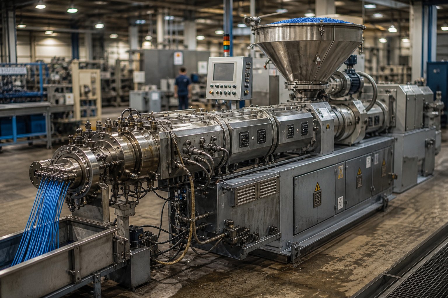
If you operate a twin screw compounding extruder line, chances are it is a co-rotating intermeshing machine — and for good reason. Compounding demands simultaneous dispersive and distributive mixing at high throughput, and no other configuration delivers both as effectively.
Consider high-filler compounding. Loading 60 to 80 percent calcium carbonate, talc, or barium sulfate into a polyolefin carrier requires the extruder to break apart agglomerates (dispersive mixing) and then spread individual particles uniformly throughout the melt (distributive mixing). The self-wiping figure-eight flow path of a co-rotating platform handles this continuously, while the ability to run at high RPM keeps throughput commercially viable. Glass fiber reinforcement presents a related but slightly different challenge — the fibers must be wetted and dispersed without excessive breakage. Modular screw designs allow engineers to position side-stuffer feeding downstream of the melting zone and use gentle conveying elements in the fiber incorporation region, preserving fiber length while still achieving full dispersion.
Color masterbatch production pushes dispersive mixing requirements even further. Pigment particles — especially organic types — must be broken down to primary particle size to avoid specks, streaks, and color inconsistency in downstream injection molding or film blowing. The intense shear generated by kneading blocks with aggressive stagger angles, combined with the narrow residence time distribution that ensures every granule receives a similar shear history, makes the co-rotating intermeshing extruder the undisputed standard for this application.
Reactive extrusion reinforces the same logic from a different angle. Whether you are grafting maleic anhydride onto polypropylene, running in-situ polymerization of thermoplastic polyurethane, or performing chain extension of recycled PET, the key requirement is precise control over how long every molecule spends in the reaction zone. A narrow RTD — a hallmark of co-rotating drag-flow conveying — means uniform conversion across the entire output stream. Pair that with independent screw speed and feed rate control, and you can fine-tune both reaction intensity and throughput without one compromising the other. Even at a lab scale twin screw extruder level, these same principles apply, making small co-rotating platforms the go-to tool for process development and formulation screening before scaling up to production equipment.
Profile Extrusion, PVC Processing, and Pressure-Dependent Applications
Switch the material from polyolefin compounds to rigid PVC, and the entire equipment conversation flips. PVC is one of the most thermally sensitive commodity polymers in industrial use. Its processing window is narrow — too much shear or too high a melt temperature triggers rapid dehydrochlorination, releasing hydrochloric acid that corrodes equipment and degrades the product. A twin screw extruder for PVC must accomplish something that seems contradictory: generate enough pressure to push a stiff, high-viscosity melt through complex profile dies while keeping mechanical energy input — and therefore melt temperature — as low as possible.
Counter-rotating intermeshing extruders, particularly conical designs with screw speeds typically between 30 and 150 RPM, solve this problem elegantly. Positive-displacement conveying builds die pressure through mechanical displacement rather than frictional drag, so the extruder delivers the force needed for die forming without overheating the melt. The LSLF (Low-Speed Late Fusion) processing philosophy keeps PVC powder partially unfused through most of the barrel length, achieving full gelation only in the final metering zone — exactly the thermal profile rigid PVC needs.
This is why counter-rotating conical machines dominate rigid PVC window profiles, UPVC pipe extrusion, door frames, cable ducting, and wood-plastic composite (WPC) decking. In each case, the application demands high pressure, low shear, and precise thermal control. Calendered sheet production follows the same logic: the calendering squeeze inherent in counter-rotating flow mechanics is not just tolerated in these applications — it is the processing mechanism that produces the desired surface finish and gauge uniformity.
Recycling and Pelletizing Operations
Recycling and pelletizing sit at the intersection of both configurations. The right choice depends entirely on what is going into the barrel and what form it needs to take coming out. Here is how specific material-application combinations typically map:
- Post-consumer polyolefin recycling (contaminated, mixed-color streams) — co-rotating intermeshing; self-wiping action handles inconsistent feedstock, and high throughput keeps cost per kilogram competitive
- Post-industrial PET recycling with devolatilization — co-rotating intermeshing; starve-fed operation and vacuum venting efficiently remove moisture and residual acetaldehyde
- Rigid PVC regrind reprocessing — counter-rotating intermeshing (conical or parallel); low-shear conveying prevents degradation of already heat-stressed PVC resin
- Twin screw pelletizing extruder for filled masterbatch — co-rotating intermeshing; high filler dispersion and consistent pellet quality require the mixing intensity and narrow RTD that co-rotating platforms provide
- WPC pelletizing from wood flour and polyolefin blends — counter-rotating intermeshing; gentle processing prevents wood fiber scorching while positive displacement generates sufficient die pressure for strand pelletizing
- Laboratory-scale formulation development and small-batch pelletizing — co-rotating intermeshing (lab scale twin screw extruder with 16 to 27 mm screws); modular screw design allows rapid configuration changes between experimental runs
Notice the pattern. Whenever the process objective centers on mixing, dispersion, or handling contaminated and variable feedstock, co-rotating wins. Whenever the objective shifts to pressure generation with minimal thermal damage — especially for PVC and other heat-sensitive systems — counter-rotating is the stronger match. Pelletizing itself is format-neutral; it is the upstream processing requirement that dictates the configuration.
Selecting the right configuration gets material through the die in optimal condition. Keeping it running day after day, however, introduces a separate set of engineering challenges — wear patterns, failure modes, and barrel replacement strategies that differ sharply between the two platforms.
Twin Screw Extruder Maintenance, Wear Patterns, and Barrel Replacement Considerations
Your extruder does not fail all at once. It fails gradually — a tenth of a millimeter at a time — until one morning the line cannot hold pressure, pellet quality drifts out of spec, and the maintenance manager is pulling screws on an emergency schedule instead of a planned one. The frustrating part? Co-rotating and counter-rotating configurations wear in fundamentally different ways, in different zones, for different mechanical reasons. Understanding those differences is the gap between proactive twin screw extruder maintenance and reactive firefighting.
Wear Patterns and Common Failure Modes
Every twin screw extruder barrel and screw assembly operates under a combination of abrasive, adhesive, corrosive, and erosive wear mechanisms. But the dominant mechanism — and the location where damage concentrates — shifts dramatically depending on which configuration is running.
Co-rotating extruders push screws at high RPM through abrasive-laden melts, and the wear signature reflects that intensity. Industry data identifies four primary high-wear zones inside twin screw extruders:
- Feeding zone — solid pellets and powder enter the barrel and grind against metal surfaces before melting begins, causing heavy mechanical abrasion
- Glass fiber and filler incorporation zone — long glass fibers entangle at the side-stuffer port and shear during rotation, forming sharp particles that intensify erosion on both flight tips and barrel liners
- Mid-barrel kneading zones — axial pressure and screw shaft deflection cause the rotating screw to bend slightly, and the resulting contact between flight edges and the barrel bore creates localized scraping wear
- Discharge zone — the cantilevered screw end sags under gravity, and when pressurized melt enters, the screw lifts, pressing its flight tip against the barrel wall in a cyclic rubbing pattern
In co-rotating machines processing 30 to 60 percent mineral or glass fillers, kneading block zones take the hardest hit. The combination of high screw speed, elevated particle velocity, and intense shear at staggered disc faces produces an erosive-abrasive wear regime where erosion rates scale roughly with the cube of particle velocity. That relationship is why a co-rotating extruder running at 800 RPM with 40 percent glass fiber can burn through screw elements several times faster than the same machine running at 400 RPM with the same formulation.
Counter-rotating extruders experience a completely different wear profile. Because these machines operate at much lower RPM, velocity-dependent erosive wear is far less severe. Instead, the dominant damage mechanism is concentrated at the intermeshing nip region, where the calendering squeeze pushes enormous separating forces outward against the barrel wall. Recall from earlier sections that counter-rotating nip forces can exceed one metric ton on a 55 mm machine — those forces do not disappear without a trace. Over thousands of operating hours, the repeated compression cycle wears the barrel bore preferentially at the nip contact angles, creating an oval distortion pattern rather than the uniform bore enlargement typical of co-rotating machines.
Corrosive wear adds another layer for counter-rotating lines processing PVC. Hydrogen chloride gas evolving from the polymer at processing temperatures attacks metal surfaces chemically. Nitrided 4140 steel corrodes at rates of 0.08 to 0.15 mm per 1,000 operating hours in rigid PVC service, compared to just 0.01 to 0.03 mm for high-nickel, high-chromium bimetallic constructions. For twin screw extruder manufacturers building counter-rotating PVC lines, specifying the wrong barrel metallurgy does not just shorten service life — it can lead to catastrophic bore failure within months.
Matching barrel and screw metallurgy to the specific wear profile of each configuration is not optional — it is the single largest variable determining component lifespan. The table below maps common metallurgical solutions to the wear mechanisms each configuration faces:
| Configuration | Dominant Wear Mechanism | Critical Wear Zone | Recommended Metallurgy |
|---|---|---|---|
| Co-rotating (abrasive compounds) | Erosive-abrasive wear from high-velocity filler particles | Kneading blocks, filler feed zone, discharge zone | CPM 10V or D2 tool steel screw elements; tungsten carbide bimetallic barrel liners; HVOF WC-Co coatings on flight tips |
| Co-rotating (unfilled or low-fill) | Adhesive wear during transients; mild abrasion | Feed zone, metering zone | Nitrided 4140 or H13 screw elements; standard iron-based bimetallic barrel liners |
| Counter-rotating (rigid PVC) | Corrosive wear from HCl evolution + compressive nip forces | Intermeshing nip region, full bore length | Stellite 6 or 12 overlay on screw flights; nickel-alloy bimetallic barrel liners |
| Counter-rotating (filled compounds) | Abrasive wear at moderate intensity + nip compression | Nip region, feed zone | High-chromium white iron overlay; high-Cr bimetallic barrel liners |
Replacement Planning and Barrel Selection
Wear patterns determine not just when components fail, but how you replace them — and the replacement workflow differs substantially between the two platforms.
Co-rotating systems benefit enormously from modular screw architecture. When a kneading block set wears past tolerance, you pull the shaft, slide off the worn elements, slide on fresh ones, and return the extruder to service. The process takes hours, not days. Practical maintenance guidance recommends treating individual element replacement as a routine scheduled event rather than an emergency — especially in high-abrasion compounding operations where kneading elements may need swapping every 3,000 to 5,000 hours while conveying elements last two or three times longer. That modularity translates into shorter planned downtime windows and lower labor cost per event.
Counter-rotating systems, particularly conical designs, present a different maintenance equation. The one-piece or limited-segment screw construction that maintains closed-chamber integrity also means that wear in one zone often requires replacing the entire screw set. The replacement events are less frequent — lower RPM and less erosive wear extend intervals — but when they occur, the scope is larger, the downtime is longer, and the cost per event is higher. For plant managers running counter-rotating PVC lines, the key to cost control is maximizing the interval between full-screw replacements through correct metallurgy selection upfront.
The barrel side of the equation deserves equal attention, and this is where many operations underinvest. A worn barrel paired with fresh screws recovers only a fraction of lost performance — the screw-and-barrel pair functions as a system, and replacing one component without assessing the other leaves clearance gaps that bleed output and melt quality. Twin screw extruder barrel replacement planning should evaluate both components simultaneously.
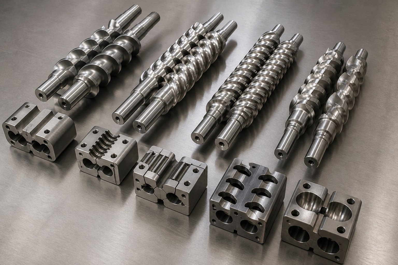
For operations running parallel co-rotating compounding lines, masterbatch production, recycling plants, or pelletizing systems, sourcing quality replacement barrels engineered for the specific wear environment is critical. NANHAIYA's Parallel Twin Screw Barrel serves exactly these applications — compounding producers, masterbatch manufacturers, recycling plants, and pelletizing operations requiring custom or replacement barrels designed for stable conveying, consistent mixing performance, and durability under high-wear processing conditions.
Whether you are sourcing from NANHAIYA or evaluating any twin screw extruder barrel supplier, the following factors should drive your selection:
- Metallurgy compatibility — the barrel liner material must match the dominant wear mechanism of your process; iron-based bimetallic for abrasive compounds, nickel-alloy bimetallic for corrosive PVC and halogenated formulations
- Dimensional precision — bore diameter tolerances directly govern screw-to-barrel clearance, which determines leakage flow, output efficiency, and melt temperature uniformity; even 0.05 mm of extra clearance compounds into measurable performance loss over a full barrel length
- Wear-resistant lining options — look for suppliers offering multiple liner chemistries (high-chromium iron-based, nickel-matrix with embedded tungsten carbides, and solid tool steel options) so you can match the liner to your specific polymer and filler system rather than accepting a one-size-fits-all solution
- Application-specific customization — barrel configurations vary by process; feed ports, vent openings, side-stuffer interfaces, and cooling channel layouts must align with your existing machine geometry and processing requirements
- Documentation and traceability — request material certificates, hardness test reports, and dimensional inspection records; a barrel without documented metallurgy is a gamble you cannot quantify
One practical rule of thumb from the reference data brings the economics into sharp focus: as screw-to-barrel clearance widens from 0.1 mm to 0.5 mm, specific energy consumption increases 6 to 12 percent and output drops 8 to 15 percent at constant screw speed. That means a worn barrel is not just a future failure risk — it is an active, ongoing drain on your energy bill and production rate every hour it stays in service. The cheapest barrel to buy is almost never the cheapest barrel to operate.
Maintaining equipment in peak condition keeps the line running. But maintenance strategy is only one variable in a much larger decision framework — one that should start before you ever purchase the machine. The final piece of the puzzle is a structured method for choosing the right configuration in the first place, based on your processing objectives, material constraints, and total cost of ownership.
How to Choose the Right Twin Screw Extruder for Your Operation
You have the technical knowledge. You understand flow mechanics, mixing modes, wear profiles, and barrel metallurgy. But when the purchase requisition lands on your desk — or when a customer halfway around the world asks you to recommend an extrusor for their new compounding line — all that knowledge needs to collapse into a single, defensible answer: co-rotating or counter-rotating?
Rather than relying on gut instinct or supplier recommendations alone, work through a structured twin screw extruder selection guide built around five questions. Each one eliminates options and narrows your decision until the right configuration becomes obvious.
Five Critical Questions Before Choosing a Configuration
- What is your primary processing objective — mixing or pressure generation? If the process demands intense dispersive and distributive mixing (compounding, masterbatch, reactive extrusion), co-rotating intermeshing is the default starting point. If the process demands high die pressure with minimal thermal input (PVC profiles, calendered sheet), counter-rotating intermeshing takes priority. Most specification errors trace back to getting this first question wrong.
- What materials and additives will be processed? Shear-robust polymers like polyolefins, ABS, and engineering resins tolerate — and benefit from — the high-speed, high-shear environment of a co-rotating machine. Shear-sensitive or thermally unstable materials like rigid PVC, certain biodegradable polymers, and heat-sensitive pharmaceutical compounds require the gentle, low-RPM conveying only a counter-rotating platform provides. If your formulation includes abrasive fillers like glass fiber or mineral concentrates at loadings above 30 percent, factor the wear implications from the previous section into your decision as well.
- What throughput and screw speed range does the operation require? Co-rotating extruders offer dramatically higher throughput per unit of screw diameter because they operate at speeds ranging from 300 to 1,200 RPM for parallel designs. Counter-rotating machines, particularly LSLF types, max out below 50 RPM and produce correspondingly lower volumetric output. If your business case depends on processing several thousand kilograms per hour through a single line, co-rotating is likely the only viable path.
- What downstream equipment must the extruder feed? A strand pelletizer or underwater pelletizing system requires consistent melt pressure and temperature — conditions a co-rotating machine manages well through metering zone design. A complex profile die with thin walls and tight tolerances demands the steady, pulsation-free pressure delivery that positive-displacement counter-rotating conveying provides. Match the extruder's output characteristics to the die or downstream device, not just to the polymer.
- What are the maintenance and total cost of ownership considerations? Co-rotating machines running abrasive formulations consume screw elements faster but benefit from modular swap-out convenience and shorter downtime per event. Counter-rotating machines wear more slowly at lower RPM but require larger-scope replacements when components do reach end of life. Budget machines under $50,000 can carry 40 percent higher five-year ownership costs due to accelerated wear and unplanned downtime — always compare documented screw and barrel service life data before committing capital.
Decision Matrix for Common Processing Scenarios
The five questions above give you a systematic path. The table below gives you a shortcut — a direct mapping of the most common processing scenarios to the configuration that handles each one best, along with the technical reasoning and the single most important parameter to prioritize during specification.
| Processing Scenario | Recommended Configuration | Primary Reasoning | Key Parameter to Prioritize |
|---|---|---|---|
| High-filler compounding (CaCO3, talc, glass fiber at 30–80%) | Co-rotating intermeshing | Self-wiping figure-eight flow achieves thorough filler dispersion at commercially viable throughput rates | Dispersive mixing intensity and screw speed range |
| Rigid PVC profile and pipe extrusion | Counter-rotating intermeshing (conical or parallel LSLF) | Positive-displacement conveying generates die pressure without exceeding PVC's narrow thermal processing window | Melt temperature control and pressure generation at low RPM |
| Reactive extrusion (grafting, chain extension, in-situ polymerization) | Co-rotating intermeshing | Narrow residence time distribution ensures uniform reaction conversion; independent speed and feed rate control allows precise tuning of reaction intensity | Residence time distribution uniformity |
| Recycled pelletizing (post-consumer polyolefin, PET) | Co-rotating intermeshing | Self-cleaning action tolerates contaminated and inconsistent feedstock; vacuum venting removes moisture and volatiles efficiently | Devolatilization capacity and throughput |
| Color masterbatch production | Co-rotating intermeshing | Aggressive kneading block configurations break pigment agglomerates to primary particle size; narrow RTD prevents over- or under-processed fractions | Pigment dispersion quality (dispersive mixing) |
| Devolatilization (solvent stripping, moisture removal) | Co-rotating intermeshing (starve-fed) | Partially filled screw channels expose maximum melt surface area under vacuum vents for efficient mass transfer | Vent zone design and vacuum capacity |
| WPC (wood-plastic composite) extrusion | Counter-rotating intermeshing | Low shear prevents wood fiber scorching; positive displacement delivers sufficient pressure for profile dies | Shear level and melt temperature control |
If you are evaluating which scenario best describes your operation, start at the top of the table and work down. Most compounding, masterbatch, and recycling operations will land firmly in the co-rotating column. Most PVC, WPC, and low-shear profile applications will land in the counter-rotating column. Hybrid situations — say, a filled PVC compound requiring both mixing and pressure — demand closer analysis, and often benefit from consultation with equipment and component suppliers who understand both platforms.
For operations already running co-rotating parallel lines — or specifying new ones — barrel and screw components eventually become the limiting factor in sustained production quality. Compounding producers, masterbatch manufacturers, recycling plants, and pelletizing operations that need replacement or custom-built parallel twin screw barrels engineered for high-wear stability can source from NANHAIYA's Parallel Twin Screw Barrel program, which supports exactly these applications with barrels designed for stable conveying, consistent mixing performance, and durability under demanding processing conditions.
Regardless of which configuration or supplier you choose, one principle holds across every row of the table above: the best twin screw extruder for compounding — or for any other application — is always the one matched to the specific material, the specific process, and the specific quality requirements of the operation it serves. No configuration is universally superior. The machine that runs your neighbor's line flawlessly may be entirely wrong for yours. Stop guessing, start with the five questions, validate against the decision matrix, and specify with confidence.
Frequently Asked Questions About Co-Rotating and Counter-Rotating Twin Screw Extruders
1. What is the main difference between co-rotating and counter-rotating twin screw extruders?
The core difference lies in how material moves through the barrel. Co-rotating screws spin in the same direction, creating a self-wiping figure-eight flow path dominated by drag flow. This produces intense dispersive and distributive mixing at high screw speeds. Counter-rotating screws spin in opposite directions, forming closed C-shaped chambers that push material forward via positive displacement. This generates high die pressure at low RPM with minimal shear heating - ideal for thermally sensitive polymers like rigid PVC. The rotation direction ultimately determines shear rate, mixing intensity, pressure capability, residence time distribution, and wear behavior.
2. Which twin screw extruder is better for PVC processing?
Counter-rotating intermeshing extruders - particularly conical LSLF (Low-Speed Late Fusion) designs running between 30 and 50 RPM - are the standard for rigid PVC processing. PVC has a very narrow thermal window, and exceeding it triggers dehydrochlorination that releases corrosive HCl gas. Counter-rotating positive-displacement conveying builds the die pressure needed for profile and pipe extrusion without generating the high frictional heat that co-rotating machines produce. The late-fusion processing philosophy keeps PVC powder partially unfused through most of the barrel, achieving full gelation only near the die, which prevents premature degradation.
3. Can a co-rotating twin screw extruder generate enough pressure for profile extrusion?
Co-rotating extruders can generate die pressure through discharge screw elements, but pressure generation is not their primary strength. They rely on drag flow rather than positive displacement, making them less efficient at building the steady, pulsation-free melt pressure that complex profile dies demand. For thin-walled or geometrically intricate profiles - especially in PVC - counter-rotating intermeshing designs deliver superior pressure consistency at lower energy input. Co-rotating machines excel instead at mixing-intensive applications like compounding, masterbatch, reactive extrusion, and devolatilization where throughput and dispersion quality matter more than raw pressure output.
4. How do wear patterns differ between co-rotating and counter-rotating extruders?
Co-rotating extruders running abrasive fillers at high RPM experience erosive-abrasive wear concentrated in kneading block zones, filler feed zones, and the discharge section. Wear rate scales roughly with the cube of particle velocity, so higher screw speeds dramatically accelerate element consumption. Counter-rotating machines wear differently - damage concentrates at the intermeshing nip region due to calendering separating forces, and PVC applications add corrosive wear from HCl evolution. Co-rotating modular screws allow quick element-by-element replacement, while counter-rotating one-piece screws may require full screw set changes. Sourcing barrels with correctly matched metallurgy - such as NANHAIYA's Parallel Twin Screw Barrel for co-rotating compounding lines - is critical for maximizing service life.
5. What are the four types of twin screw extruders?
Twin screw extruders are classified along two axes - rotation direction and intermeshing degree - producing four subtypes. Co-rotating intermeshing is the most common, dominating compounding, masterbatch, and recycling with self-wiping drag-flow mixing at 200-1200+ RPM. Counter-rotating intermeshing uses positive displacement in closed chambers at 10-150 RPM, excelling at rigid PVC profiles and pipe extrusion. Co-rotating non-intermeshing provides gentle distributive mixing with high free volume for specialty devolatilization. Counter-rotating non-intermeshing offers minimal shear for niche chemical processing requiring extended residence time. Most production floors run one of the two intermeshing types.
Written by
Nanhaiya Technical Team
Zhoushan Nanhaiya Plastic Machinery Co., Ltd.
The Nanhaiya technical team supports screw and barrel manufacturing projects through application review, technical communication, custom manufacturing coordination, and production and quality control.
Discuss Your Application
Related Articles
More insights on screw barrel technology and plastics processing.

What Nobody Tells You About Screw Barrel For Plastic Machine Design
Oct 10, 2026
Learn how screw barrel for plastic machine design affects melt quality, throughput, and wear life. Covers geometry, resin matching, troubleshooting, and sourcing.
Read Article
Single Screw Extruder for Sheet: Stop Guessing, Start Specifying
Oct 9, 2026
Learn how to specify a single screw extruder for sheet production. Covers screw geometry, resin-specific processing, troubleshooting, and maintenance best practices.
Read Article
PE Pipe Extruder Machine: What Datasheets Won't Tell You
Oct 9, 2026
Learn how a PE pipe extruder machine works, key specs explained, material grade selection, maintenance tips, and buyer guidance beyond the datasheet.
Read ArticleLooking for something else?
Search by material, symptom or product and jump straight to the relevant page.
These are navigation suggestions based on keyword matching — not a quotation, not a delivery commitment, and not a substitute for engineering review. Final specification is confirmed by our engineers against your drawings and processed material.
Need help with screw barrel selection?
Share your machine model, processed material and application. Our team can help with pricing and technical support.