


What Is Blown Film Gauge Variation and Why It Matters
Imagine running your blown film line for hours, only to discover that finished rolls fail customer inspection because some areas are too thin while others carry excess material. That frustration has a name, and understanding it is the first step toward eliminating it.
Defining Gauge Variation in Blown Film Extrusion
Blown film gauge variation is the unintended deviation in film thickness that occurs either around the bubble's circumference or along the machine direction during extrusion. It is typically expressed as a percentage deviation from the target (nominal) thickness. A line targeting 1-mil film with measured values swinging between 0.9 and 1.1 mil, for example, exhibits roughly ±10% variation.
Blown film gauge variation is the measurable difference between the intended film thickness and the actual thickness at any point across the web or along its length, caused by process, equipment, or material inconsistencies during blown film extrusion.
Why does blown film gauge variation matter so much? The consequences reach every corner of a film operation:
- Material giveaway — processors compensate for thin spots by running heavier than necessary, wasting resin on every roll produced.
- Customer rejects — out-of-spec thickness triggers failed quality checks and returned shipments.
- Reduced mechanical performance — thin areas become weak points for puncture, tear, and seal failure.
- Downstream converting issues — uneven film feeds poorly through printing, laminating, and bag-making equipment, causing jams and registration errors.
Why Gauge Consistency Is the Foundation of Film Quality
A core principle drives every topic in this guide: mass in equals mass out. If the extruder delivers an inconsistent mass flow rate, that instability travels directly through the die and into the bubble. No air ring adjustment or winder correction can fully undo what started upstream. As Plastics Engineering notes, addressing instability at its source typically yields greater quality improvements than tightening individual downstream setpoints.
Blown film thickness deviation causes span the entire production line — from resin rheology and extruder wear, through die flow distribution and cooling symmetry, all the way to collapsing frame alignment and winder tension. Solving gauge problems requires a systematic approach rather than isolated adjustments. This resource covers that full diagnostic-to-resolution cycle: identifying variation patterns, classifying their type, tracing root causes, selecting the right measurement technology, applying corrections, and building maintenance protocols that keep thickness on target run after run.
Each section ahead addresses a specific piece of this workflow, and together they form a complete reference for anyone asking how to diagnose and fix blown film quality problems from uneven thickness — whether you are a process engineer, a line operator, or a plant manager accountable for yield.
Film Thickness Units and Gauge Conversion Explained
Before you can diagnose or correct any thickness inconsistency, you need to speak the same measurement language as your customers, your quality team, and your equipment. Sounds straightforward? In practice, plastic film thickness measurement units explained across three different systems — gauge, mils, and microns — create confusion that leads to real specification errors, especially in global supply chains.
Mils, Microns, and Gauge — Understanding the Units
Three units dominate the blown film industry, and each describes the same physical property from a different starting point:
- Mil — one thousandth of an inch (0.001 in.). This is the standard unit across North American film specifications.
- Micron (µm) — one thousandth of a millimeter (0.001 mm). This SI metric unit is the international standard used throughout Europe and Asia.
- Gauge — in the plastic film context, one gauge unit equals one hundredth of a mil (0.01 mil), or 0.254 microns. So 100 gauge equals exactly 1.0 mil, which equals 25.4 microns.
Here is the relationship you'll want to memorize: 1 mil = 100 gauge = 25.4 microns = 0.0254 mm. Every conversion in this section flows from that single equivalence.
One critical distinction trips people up regularly. Film gauge increases linearly with thickness — a 200-gauge film is twice as thick as a 100-gauge film. Wire gauge, by contrast, works in the opposite direction, where higher numbers mean thinner wire. If you are crossing over from metal fabrication, expect this reversal to feel counterintuitive at first.
Another common pitfall involves the term "mil" itself. Internationally, "mil" is sometimes misread as "millimeter." Since 1 millimeter equals roughly 39.37 mils, that single-letter mix-up creates a nearly 40-fold thickness error — enough to reject an entire production run. Always state units explicitly on purchase orders, spec sheets, and inspection reports. Never assume your reader shares your regional convention.
How to Convert Mil to Gauge and Micron to Gauge for Plastic Film
You'll encounter these conversions daily when reconciling customer specifications with your process settings or quality data. The formulas are simple:
- Mils to gauge: multiply by 100 (e.g., 1.5 mil × 100 = 150 gauge)
- Gauge to mils: divide by 100 (e.g., 80 gauge ÷ 100 = 0.80 mil)
- Microns to gauge: divide by 0.254 (e.g., 25.4 µm ÷ 0.254 = 100 gauge)
- Gauge to microns: multiply by 0.254 (e.g., 150 gauge × 0.254 = 38.1 µm)
- Mils to microns: multiply by 25.4 (e.g., 2.0 mil × 25.4 = 50.8 µm)
So what is 100 gauge in mils and microns? It is exactly 1.0 mil and 25.4 microns — the clean, round-number benchmark the entire film industry uses as a reference point.
A practical tip worth noting: small rounding errors compound across tight tolerance ranges. If your quality tolerance is ±2 microns and you round 0.5 mil to 13 microns instead of the exact 12.7, that discrepancy alone can push a borderline reading from pass to fail. Carry at least two decimal places when converting for QC documentation.
Practical Conversion Reference for Film Processors
The table below serves as a micron to gauge conversion chart for film processors, covering the full range of typical blown film thicknesses — from thin shrink wrap through heavy-duty industrial sacks.
| Common Film Description | Gauge | Mils | Microns (µm) | Millimeters (mm) |
|---|---|---|---|---|
| Light-duty shrink/cling film | 60 | 0.60 | 15.24 | 0.01524 |
| Standard shrink film | 75 | 0.75 | 19.05 | 0.01905 |
| Thin stretch film | 80 | 0.80 | 20.32 | 0.02032 |
| Retail poly bags / reference benchmark | 100 | 1.00 | 25.40 | 0.02540 |
| General-purpose bags | 150 | 1.50 | 38.10 | 0.03810 |
| Medium-duty bags / liners | 200 | 2.00 | 50.80 | 0.05080 |
| Heavy-duty liners | 300 | 3.00 | 76.20 | 0.07620 |
| Heavy-duty sack film | 400 | 4.00 | 101.60 | 0.10160 |
| Industrial-grade bags | 500 | 5.00 | 127.00 | 0.12700 |
| Extra-heavy industrial film | 600 | 6.00 | 152.40 | 0.15240 |
Two governing standards define how these thickness values should be measured and validated. ASTM D6988 covers the determination of plastic film thickness using a dead-weight contact micrometer, while ISO 4593 provides the international equivalent method for mechanical scanning measurement. Both standards establish consistent measurement protocols that ensure your reported values are comparable across suppliers, customers, and quality audits.
One final distinction matters deeply for blown film gauge variation analysis: nominal gauge versus actual measured gauge. The nominal value on a spec sheet is a target — the thickness you intend to produce. Actual measured gauge, captured at specific points across the web and along its length, reveals what the process truly delivers. Variation tolerances are typically expressed as a ±percentage of the nominal value (for example, "80 gauge ±10%" means acceptable readings fall between 72 and 88 gauge). Understanding that gap between target and reality is exactly what separates a controlled process from one bleeding money through material giveaway and rejects.
With these measurement fundamentals in place, the real diagnostic work begins — recognizing which patterns of thickness deviation your film exhibits and tracing each pattern back to its specific mechanical or process origin.
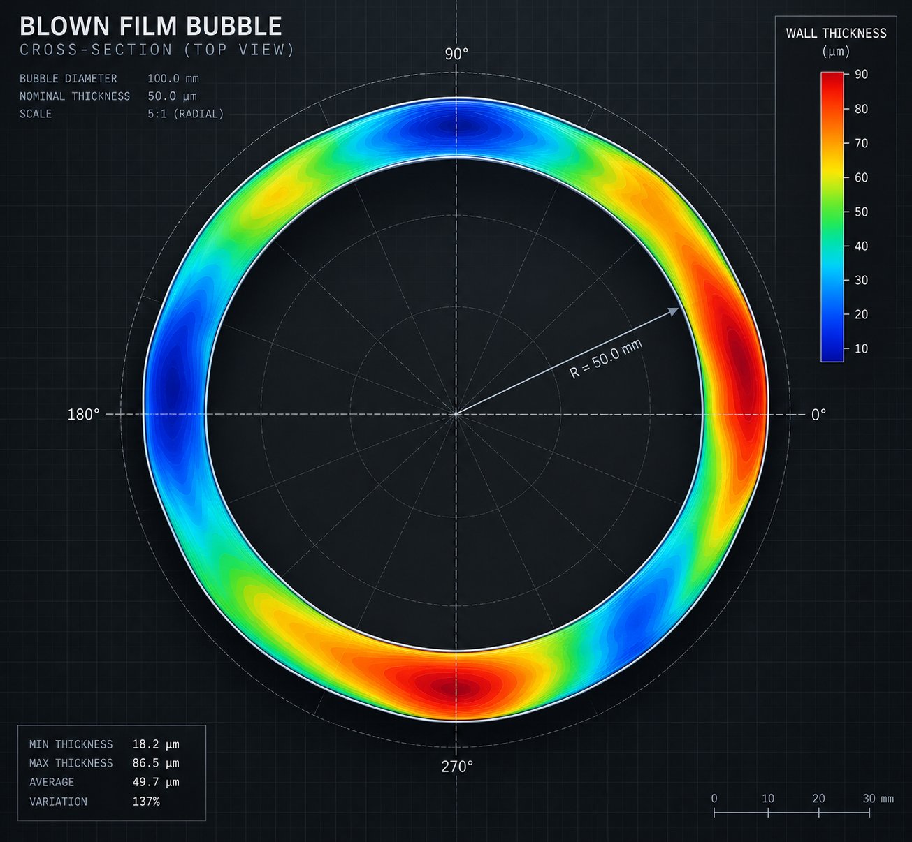
Four Types of Gauge Variation and How to Classify Each Pattern
Here is something that trips up even experienced operators: not all thickness inconsistency comes from the same source. A persistent thick band that stays locked to one spot on the die looks identical on a finished roll to one caused by a drafty doorway near the air ring — yet the corrections are completely different. Fix the wrong one and you have wasted a shift while the real culprit keeps running.
The fastest path to a solution is classifying the pattern before reaching for any wrench. Industry troubleshooting guidance consistently separates machine-direction gauge changes from circumferential gauge bands and uses bubble shape and frost-line behavior as diagnostic clues to narrow the source. The framework below breaks blown film thickness problems into four distinct types, each pointing toward a different section of the line.
Circumferential Variation Originating at the Die
Picture a thick-thin pattern that repeats around the bubble and stays anchored to the same angular position relative to the die — shift after shift, roll after roll. That stationarity is your strongest clue. When the band follows the die rather than any external reference, the flow distribution inside the die itself is the primary suspect.
- Likely root causes: Uneven die gap from improperly adjusted or fatigued die bolts, restricted or partially blocked flow channels due to carbon buildup or degraded polymer deposits, and temperature asymmetry across the die body from a failed heater band or poorly seated thermocouple.
- First diagnostic steps: Mark the bubble orientation and correlate the thick band's angular position with the die bolt map. Inspect die lip condition for buildup or scoring. Verify every heater zone with a surface-contact thermocouple or calibrated infrared pyrometer — a deviation greater than 3 °C in metering or die zones typically produces visible gauge bands.
- Correction actions: Adjust die bolts methodically (one bolt at a time, small increments). Schedule a die pull for cleaning if deposits are suspected. Replace any failed heater bands and reseat loose thermocouples.
A two-lobe pattern — two high zones and two low zones spaced roughly 180° apart — often points to die assembly issues such as mandrel centering, side-fed flow distribution, or thermal asymmetry. If the lobes rotate when you rotate the die, the pattern is confirmed as die-fixed.
Circumferential Variation Caused Post-Die
What if the thick-thin bands shift position, rotate, or drift relative to the die over time? That behavior rules out a die-originated cause and points squarely at influences acting on the bubble after the melt exits the die lip.
- Likely root causes: Uneven air ring airflow from a dirty, tilted, or off-center air ring; IBC (internal bubble cooling) imbalances causing asymmetric internal cooling; ambient drafts from open doors, overhead HVAC, or nearby equipment fans; and bubble instability from inadequate bubble locking or cage misalignment.
- First diagnostic steps: Watch the frost line carefully. A tilted or wavy frost line that stays fixed to the room — not to the die — is a strong indicator of an air ring or environmental issue. Level and center the air ring. Inspect all airflow passages, vanes, and lip segments for contamination or damage. Check whether the band position correlates with fixed room features like doorways or ventilation outlets.
- Correction actions: Clean and re-level the air ring. Seal or redirect ambient air sources. Retune IBC PID control if the IBC valve is hunting at greater than 0.5 Hz. On lines with bubble cages, verify cage alignment and contact symmetry.
An important nuance: a tipped or dirty air ring can create a circumferential thickness variation blown film pattern that looks exactly like poor die adjustment. Many processors have spent hours tweaking die bolts when the actual problem was a few millimeters of air ring misalignment. Always rule out post-die influences before committing to die-side corrections.
Machine-Direction Gauge Shifts
Instead of a band at one angular position, imagine the entire thickness profile rising and falling over time — the whole average gauge cycling up and down as the web advances. You might notice it first as rolls that vary in weight from one to the next, or as a slow drift visible on a trending chart.
Machine direction gauge variation causes trace almost exclusively to upstream melt delivery instability. The bubble is simply reflecting what the extruder is feeding it.
- Likely root causes: Extruder output surging from worn screw flights or excessive barrel clearance (even a 1% increase in effective flight clearance can increase output pulsation amplitude by 8–12%), screw speed fluctuations from drive belt slip or motor regulation problems, back pressure variation from screen pack fouling, inconsistent feed throat conditions including bridging or starve feeding, and resin batch-to-batch viscosity changes.
- First diagnostic steps: Trend head pressure and melt temperature over a 30-minute window. A periodic component in the pressure signal — especially one matching the screw rotation frequency — strongly implicates mechanical wear. Cross-reference with screw speed, motor load, feeder data, nip speed, and frost line height on the same time base. If the variation is slow (hours), suspect feed or resin changes. If it cycles in seconds to minutes, suspect extruder mechanics or thermal control.
- Correction actions: Measure screw-to-barrel clearance quantitatively — do not rely on visual inspection alone. Verify drive train integrity. Check barrel zone temperatures independently with external instruments. Stabilize feed conditions.
A key diagnostic principle applies here: do not ask a circumferential air ring control to fix an upstream machine-direction problem. Local airflow zones correct polar profile errors. They cannot compensate for an unstable total mass flow arriving at the die.
Downstream Mechanical Distortion
This is the variation type that most often masquerades as something else. The scanner profile may look perfectly acceptable, yet finished rolls develop hard bands, wrinkles, baggy lanes, or telescoping. Alternatively, a modest thickness band from the die gets amplified into a commercially unacceptable defect during winding.
- Likely root causes: Collapsing frame misalignment creating uneven layflat tension, nip roll pressure that varies across the web width, winder tension that is too high (stretching thin areas further) or too low (creating wrinkles), oscillating haul-off synchronization errors, and roller misalignment introducing localized stretching.
- First diagnostic steps: Compare the cross-web thickness profile against roll hardness measurements and the location of visual defects. If the hard bands or baggy lanes do not correspond to thickness peaks and valleys, the problem is tension-related, not gauge-related. Trend winder tension and correlate with defect timing. A clean absence of correlation between gauge data and winding defects confirms a downstream mechanical origin.
- Correction actions: Realign the collapsing frame and verify nip roller parallelism. Audit winder taper-tension settings. Inspect roller surfaces for wear or damage. Measure actual web tension rather than relying solely on torque or dancer position readings.
The critical insight with downstream distortion is that tension does not replace gauge control, and gauge control does not replace proper tension management. The two data sets — thickness profile and tension profile — should be compared side by side rather than treated as interchangeable. A small but real gauge band combined with excessive winding tension can produce roll defects far worse than either issue alone.
Putting the Classification to Work
When you encounter a thickness problem, run through this decision sequence before making any adjustments:
- Is the pattern circumferential or machine-direction? Circumferential means the variation repeats around the bubble. Machine-direction means the overall thickness drifts or cycles along the web length.
- If circumferential, is the band fixed to the die or to the room? Die-fixed points to die internals. Room-fixed or drifting points to air ring, IBC, or environment.
- If machine-direction, does the cycle frequency match screw rotation, heater cycling, or feed events? Matching a mechanical frequency confirms the specific upstream source.
- Does the roll defect correlate with the thickness profile? If not, the issue is downstream handling, not gauge.
This systematic approach to diagnosing blown film thickness problems prevents the single most common troubleshooting mistake — adjusting the wrong part of the line and inadvertently introducing a new source of variation on top of the original one.
Of course, the types of blown film gauge variation patterns described above assume a reasonably consistent raw material entering the extruder. In reality, different polymer families — and especially recycled content — respond to the same process conditions in dramatically different ways, shifting which variation type dominates and how aggressively it manifests.
Resin Rheology and Recycled Content Effects on Gauge Uniformity
You could have the most perfectly centered die, a spotless air ring, and rock-solid extruder output — and still fight persistent thickness inconsistency if the polymer itself does not distribute evenly around the bubble. How resin type affects blown film gauge variation is one of the most underappreciated factors in the entire process chain, yet it determines the baseline uniformity you can achieve before any equipment correction even comes into play.
How Polymer Type and Melt Behavior Affect Thickness Uniformity
Three rheological properties govern how evenly a molten polymer stretches as the bubble inflates:
- Melt flow index (MFI) — a measure of how easily the polymer flows under a standard load. Higher MFI resins flow more readily but often have less resistance to non-uniform stretching. The melt flow index effect on film thickness consistency is direct: a resin that flows too easily at processing temperature tends to thin out in slightly hotter zones and thicken in cooler ones, amplifying any thermal asymmetry the die or air ring introduces.
- Melt strength — the resistance of the molten polymer to stretching before it breaks or sags. High melt strength acts like a built-in self-correcting mechanism during bubble inflation, resisting localized thin spots as the film stretches biaxially.
- Extensional viscosity — specifically, strain-hardening behavior under elongational flow. Polymers that exhibit strong strain hardening effectively "push back" harder the more they are stretched, naturally evening out thickness differences around the circumference.
These three properties vary dramatically across polyethylene families, and that variation directly explains why some resins practically run themselves while others demand constant attention.
LDPE (low-density polyethylene) owes its reputation as a forgiving blown film resin to long-chain branching. Those branches create high melt strength and pronounced strain hardening under extensional flow. The result? LDPE distributes more uniformly around the bubble, tolerates modest die-gap asymmetry without producing severe gauge bands, and stabilizes the bubble against minor disturbances. Research presented at SPE ANTEC confirmed that LDPE resins consistently exhibited substantially higher melt strength than LLDPE, with blends showing a synergistic melt-strength increase even at modest LDPE additions.
LLDPE (linear low-density polyethylene) tells a different story. Its linear chain architecture delivers excellent toughness — superior dart impact, tear, and puncture performance compared to LDPE — but at a rheological cost. Lower melt strength and the absence of significant long-chain branching mean LLDPE stretches more readily under localized stress, making any die-gap or cooling asymmetry show up more aggressively in the finished thickness profile. Bubble stability is often reduced as well, particularly at higher blow-up ratios.
This is precisely why LLDPE vs LDPE gauge uniformity in blown film is rarely an either-or choice. Processors routinely blend the two, using LDPE's rheological strengths to compensate for LLDPE's processing weaknesses while preserving the mechanical performance LLDPE brings to the final film. Dow Chemical's study demonstrated that adding even 10-20% LDPE to LLDPE produced a dramatic, synergistic boost in melt strength — far exceeding what a simple linear blending rule would predict. That synergy translates directly to better bubble stability and improved gauge uniformity on the line.
HDPE (high-density polyethylene) introduces a narrower processing window that makes thickness control more demanding. Its high crystallinity and relatively low melt strength mean the transition from melt to solid happens abruptly, leaving a shorter time and distance for the polymer to distribute evenly. HDPE films are especially sensitive to die-gap accuracy, cooling symmetry, and frost-line consistency. Even small thermal imbalances that an LDPE run would absorb without visible effect can produce distinct gauge bands in HDPE.
Metallocene LLDPE (mLLDPE) deserves separate attention. Produced with single-site catalysts, mLLDPE has a very narrow molecular weight distribution and uniform short-chain branching. While this precision delivers outstanding film properties — including lower seal initiation temperature and improved optics — it also means lower melt strength and reduced shear thinning compared to conventional Ziegler-Natta LLDPE. In practice, mLLDPE can be more challenging to process with tight gauge control, and many converters blend it with LDPE at 15-30% levels specifically to restore adequate melt strength for stable bubble formation.
The following summary captures how each polymer family typically behaves and what process adjustments help maintain thickness consistency:
- LDPE: High melt strength, strong strain hardening. Naturally good gauge uniformity. Tolerates moderate die-gap variation. Recommended adjustment: Standard processing; use as a blending component to improve other resins' processability.
- LLDPE (Ziegler-Natta): Lower melt strength, good toughness. More sensitive to die and cooling asymmetry. Recommended adjustment: Blend with 10-30% LDPE for improved bubble stability and gauge uniformity; tighten die-gap tolerances.
- mLLDPE (metallocene): Very low melt strength, narrow molecular weight distribution. Most sensitive to process variation. Recommended adjustment: Blend with 15-30% LDPE; reduce BUR if bubble instability appears; ensure tight thermal control.
- HDPE: Low melt strength, narrow processing window, rapid crystallization. Highly sensitive to die gap and cooling balance. Recommended adjustment: Minimize die-gap variation, ensure uniform air ring flow, maintain tight frost-line height control.
Recycled Content and PCR Impact on Gauge Control
Sustainability mandates and brand-owner commitments are pushing post-consumer resin (PCR) percentages higher across the blown film industry. That trend creates a real and growing challenge for gauge control, one that many processors are encountering for the first time as they scale PCR from trial runs to full production.
The post consumer resin PCR gauge control challenges are rooted in variability itself. Unlike virgin resin produced to tight specifications from a single reactor, PCR is collected from diverse waste streams where the original resin types, additives, degradation history, and contamination levels vary from bale to bale. The practical consequences for thickness consistency include:
- Batch-to-batch viscosity variation — MFI can swing significantly between PCR lots, even from the same supplier. Each shift in viscosity changes how the melt distributes through the die and how it responds to stretching during bubble inflation.
- Contamination effects on melt homogeneity — residual inks, adhesives, mixed polymer fractions, and filler carryover create localized viscosity differences within the melt stream. These micro-heterogeneities produce small-scale flow irregularities that manifest as noisy, unstable gauge readings.
- Degradation and crosslinking — repeated thermal cycling during the PCR reprocessing chain can partially degrade or crosslink polymer chains, creating inconsistent melt strength and flow behavior that shifts unpredictably.
- Moisture and volatiles — inadequately dried PCR releases moisture and trapped volatiles during extrusion, causing melt surging, bubble instability, and erratic output that directly translates to machine-direction gauge variation.
The higher your PCR percentage, the tighter your upstream process control must be to maintain acceptable gauge uniformity. Consistent melt temperature, thorough distributive mixing, pre-drying protocols, and stable screw performance all become non-negotiable rather than merely desirable. Industry guidance specifically identifies resin rheology, blend ratio, additive concentration, regrind condition, moisture, and bulk density as upstream variables that can appear downstream as average-gauge drift, bubble movement, or unstable output that no air ring can correct.
A critical diagnostic point is worth emphasizing: resin-related variation manifests primarily as machine-direction instability — the overall thickness drifting or cycling over time rather than producing a fixed circumferential band. This machine-direction signature can mask or amplify die-related circumferential patterns if it is not identified and addressed first. Imagine chasing a gauge band around the die bolt map when the real problem is a changing melt viscosity from inconsistent PCR feed. You will never find a stable correction because the underlying process keeps shifting beneath you.
The practical rule is straightforward: stabilize the resin and feed system before fine-tuning die or air ring settings. Verify that MFI testing is part of your incoming PCR quality protocol. Blend PCR lots when possible to average out batch variation. And recognize that the same die gap, temperature profile, and air ring configuration that produced excellent gauge uniformity on virgin LLDPE may need significant adjustment — or additional LDPE blending — when PCR content rises above 20-30%.
Resin behavior sets the floor for achievable thickness uniformity. But even a perfectly consistent polymer still needs a stable, precisely controlled melt delivery system to reach the die in optimal condition — and that puts the spotlight squarely on the extruder, blow-up ratio, and the thermal process parameters that connect them to the finished bubble.

Critical Process Parameters From Extruder to Bubble
A perfectly characterized resin still produces unacceptable thickness variation if the process parameters governing its journey from pellet to solidified film are not tightly controlled. Two groups of variables dominate this journey: the bubble geometry parameters — blow-up ratio and frost line height — that determine how the melt stretches, and the extruder output parameters that determine how consistently that melt arrives at the die in the first place. Neglecting either group while optimizing the other is a recipe for frustration.
Blow-Up Ratio, Frost Line Height, and Their Gauge Effects
Blow-up ratio (BUR) is the ratio of the inflated bubble diameter to the die diameter. A 200 mm die producing a 500 mm bubble operates at a BUR of 2.5:1. Simple geometry — yet the blow up ratio effect on film gauge uniformity is anything but simple, because BUR acts as an amplifier for every asymmetry already present in the system.
Imagine a die with a minor gap variation — say, one side is 0.02 mm wider than the other. At a low BUR of 1.5:1, the transverse stretching is moderate and the resulting thickness difference in the finished film may be barely measurable. Increase BUR to 3.0:1 and that same 0.02 mm gap error gets stretched across a much larger circumference. The thin zone thins further, the thick zone stays relatively heavy, and the circumferential gauge spread widens significantly. As Zonmon's BUR analysis emphasizes, gauge variation may originate from uneven die flow or cooling, but BUR determines how aggressively that initial error expresses itself in the finished product.
This amplification effect explains a common troubleshooting puzzle: a line produces acceptable gauge uniformity on one product but terrible uniformity on another, with no equipment changes between runs. The difference is often BUR. A wider film requiring higher BUR exposes die-gap imperfections that a narrower film at lower BUR simply masks.
Frost line height — the vertical distance from the die lip to the point where the bubble transitions from transparent melt to hazy, solidified film — controls the duration of melt stretching before the polymer crystallizes and locks in its final dimensions. A higher frost line means the melt stays extensible longer, allowing more time for both machine-direction drawdown and transverse inflation to act on the film. A lower frost line freezes the film quickly, reducing the stretching window.
The frost line height and thickness variation blown film relationship works in two ways:
- Inconsistent frost line height across the circumference — caused by uneven cooling — creates circumferential gauge variation because portions of the bubble solidify at different stages of stretching. One side may still be stretching while the other has already frozen, producing a persistent thick-thin pattern.
- Frost line height fluctuating over time — caused by bubble pressure instability, IBC control oscillation, or melt temperature drift — creates machine-direction gauge variation as the solidification point moves up and down, altering the effective stretch ratio continuously.
Here is the critical insight many processors miss: BUR and frost line height create compound effects that must be optimized together, not independently. Increasing BUR without sufficient cooling capacity raises the frost line, extending the stretching window and potentially destabilizing the bubble. Lowering frost line height by increasing cooling air volume while maintaining a high BUR can over-cool one side of the bubble before the other, worsening circumferential variation. The stable production target, as process engineering references confirm, is a proven process window where BUR, frost line, output, and cooling are balanced together — not a single "best" setting for any one variable in isolation.
A practical approach when dialing in a new product: start at a moderate BUR within the resin supplier's recommended range, set cooling to achieve a stable, level frost line, and only then incrementally adjust BUR toward your target width while monitoring the gauge profile at each step. If the gauge spread widens faster than the BUR increase warrants, the die gap or cooling balance needs attention before pushing BUR further.
Extruder Output Stability as the Prerequisite for Gauge Control
Every blown film process parameters for thickness control discussion eventually arrives at the same foundational truth: mass in equals mass out. If 100 grams of polymer enter the die in one second and 97 grams enter the next second, the bubble wall gets thinner during that second — regardless of how perfectly the die gap, air ring, and frost line are set. No downstream correction system can manufacture the missing 3 grams.
This is why extruder output stability is not just one factor in gauge control — it is the prerequisite. A segmented air ring can redistribute cooling to even out circumferential thickness, but it cannot add material that was never delivered. An automatic die bolt system can fine-tune flow distribution, but it responds in minutes while output surges may cycle in seconds. Stable melt delivery is the foundation everything else builds on.
Four key extruder variables directly govern output consistency:
- Screw speed consistency — even small fluctuations in RPM translate to proportional output changes. Drive belt slip, motor regulation issues, or inverter instability can create periodic output cycles that appear as machine-direction gauge bands in the finished film. A 1% screw speed variation may seem trivial, but at high extrusion rates it represents a measurable mass-flow change every revolution.
- Barrel temperature zone control — as extrusion process expert Jim Frankland explains, Zone 1 barrel temperature is particularly critical because it governs the initiation of melting and the frictional drag that drives solids conveying. Setting Zone 1 too far below the polymer's melting point delays melt formation and effectively shortens the melting length. Setting it too far above reduces melt-film viscosity and shear stress, actually decreasing the melting rate and output — the opposite of what most operators intend. The ideal Zone 1 setting is slightly above the polymer's melting point. Downstream zones primarily trim the temperature profile rather than adding significant energy, since the mechanical drive power far exceeds total heater wattage on commercial-sized extruders.
- Back pressure stability — pressure at the die entrance reflects the combined resistance of the screen pack, adapter, and die flow channels. A slowly loading screen pack gradually increases back pressure, shifting the extruder's operating point and changing output. Sudden screen changes can create step-change pressure disturbances. Diagnostic guidance from Gauge Advisor identifies screen-pack loading as one of the most common causes of gradually rising pressure and drifting output, recommending that processors trend pressure before and after filtration to separate filter restriction from other sources.
- Screw and barrel wear condition — this is where extruder screw barrel wear gauge variation becomes one of the most consequential yet most frequently deferred maintenance issues in blown film operations.
A worn screw or barrel with excessive flight-to-bore clearance allows molten polymer to leak backward over the screw flights — a phenomenon called melt slip-back or reverse leakage flow. The result is not a simple, steady output reduction. Instead, the leakage creates periodic output surges as the screw alternately pressurizes and loses pressure in the metering zone. These surges produce extruder output surging machine direction gauge bands — repeating thickness cycles in the machine direction that track with screw rotation frequency or its harmonics.
The effect is insidious because it worsens gradually. A new screw-and-barrel set has tight clearances, and the metering zone efficiently seals against backflow. As thousands of processing hours accumulate, abrasive fillers, glass fibers, recycled content contaminants, and even the polymer itself wear the flight lands and bore surface. Clearance opens. Output pulsation amplitude grows. The gauge variation that was ±3% on a new barrel slowly becomes ±6%, then ±8%, and operators compensate by running heavier nominal gauge or accepting wider tolerances — often without recognizing that wear is the underlying driver.
Barrel temperature inconsistency compounds the problem. If a worn heater band or failed thermocouple allows one zone to run hotter or colder than its setpoint, the melt viscosity in that region shifts. Since die flow distribution depends on uniform viscosity across the entire melt stream, a localized viscosity change translates directly into uneven flow around the die — creating circumferential gauge variation on top of any machine-direction surging from wear-related output instability. You end up chasing two superimposed patterns simultaneously, which is why experienced troubleshooters check extruder condition before investing time in die-gap adjustments.
When screw and barrel clearance measurements confirm that wear has exceeded acceptable limits — typically when flight clearance reaches 2-3 times the original specification — replacement is the only effective correction. Attempting to compensate with higher screw speed, adjusted temperature profiles, or tighter die-bolt settings only masks the symptom while the root cause continues deteriorating. For processors sourcing replacement components, precision manufacturing and correct metallurgical specification of the new barrel and screw are essential to restoring original output stability. NANHAIYA's custom and replacement single screw barrels for film extrusion lines offer processors a resource for matching barrel dimensions, bore finish, and material hardness to their specific resin and production requirements — a critical factor in ensuring that the replacement delivers the tight clearances and consistent melt delivery that gauge control demands.
The bottom line for blown film process parameters for thickness control is a clear hierarchy of priorities:
- Verify extruder mechanical condition — screw and barrel wear, drive integrity, feed throat function.
- Stabilize thermal profile — confirm all heater bands, thermocouples, and cooling systems are functioning correctly, with Zone 1 set appropriately for the polymer.
- Confirm output consistency — trend head pressure and melt temperature at production speed for at least 30 minutes, looking for periodic or drifting patterns.
- Optimize BUR and frost line together — adjust bubble geometry only after upstream delivery is confirmed stable.
- Fine-tune die gap and air ring — make circumferential corrections last, once you are confident the total mass flow is steady.
Blown film gauge control begins at the extruder. If melt delivery is unstable, no combination of die adjustment, air ring tuning, or automatic control can fully compensate — the variation simply shifts from one pattern to another.
Following this sequence prevents the most expensive troubleshooting mistake in the industry: spending hours adjusting downstream equipment to correct a problem that originates upstream. It also raises a natural follow-up question — once you have a stable process delivering consistent melt to a well-tuned die, how do you measure the resulting thickness profile accurately enough to verify your improvements and catch any regression before it reaches the customer?
Gauge Measurement Technologies Compared
You have identified your variation pattern, classified the type, and traced the root cause back to the die, the air ring, or the extruder. You have made corrections. But here is the question that determines whether those corrections actually worked: how are you measuring the result? The accuracy, speed, and coverage of your thickness measurement directly determine whether you catch a remaining problem, verify a genuine improvement, or simply move forward on assumptions.
Blown film thickness measurement methods compared side by side reveal significant trade-offs in accuracy, cost, film compatibility, and whether the technology supports real-time process control or only after-the-fact verification. Choosing the wrong measurement approach for your specific variation challenge is like diagnosing an engine with a stethoscope when you need an oscilloscope — you might hear something, but you will miss the detail that matters.
Inline Measurement Technologies for Continuous Monitoring
Five primary measurement methods cover the range from simple handheld spot-checks to full-web continuous scanning. Each operates on a different physical principle, and that principle determines what the sensor can and cannot see.
| Technology | Measurement Principle | Typical Accuracy | Cost Range | Inline / Offline | Best-Suited Film Types | Key Limitations |
|---|---|---|---|---|---|---|
| Beta Gauge (Nuclear Absorption) | Measures attenuation of beta radiation passing through the film; attenuation correlates to mass per unit area, converted to thickness using known density | ±2-5 µm | High | Inline (scanning) | Most monolayer and multilayer films; works with opaque, filled, and pigmented films | Requires NRC regulatory licensing and radiation safety program; measures mass-per-area, not true geometric thickness; source disposal challenges; escalating regulatory burdens driving industry shift toward non-nuclear alternatives |
| Capacitance Sensor | Measures change in electrical capacitance as film passes between sensor plates; capacitance varies with thickness and dielectric constant of the polymer | ±1-3 µm | Medium | Inline (scanning) | Non-conductive films; best for unfilled polyethylene, polypropylene, and similar pure polymers | Sensitive to moisture, conductive additives, carbon black, and metallic pigments; requires recalibration when switching resin types; dielectric constant variation between polymer lots can introduce measurement error |
| Infrared (IR) Sensor | Measures absorption of specific infrared wavelengths by the polymer; absorption intensity correlates to thickness at characteristic wavelengths | ±1-3 µm | Medium-High | Inline (scanning) | Transparent and semi-transparent films; can resolve individual layer thicknesses in multilayer structures when layers have distinct IR absorption bands | Requires optical access (non-opaque films); heavily filled, carbon-black, or metallized films block IR transmission; calibration must match specific polymer chemistry |
| Gravimetric / Weight-per-Area | Weighs a known area of film and calculates average thickness from mass, area, and polymer density | ±2-5 µm (average only) | Low | Offline | Any film type regardless of color, fill, or layer count | Provides only an average thickness for the measured area — cannot detect cross-web profile or localized thin spots; requires accurate density value; slow, manual process |
| Contact Micrometer | Measures physical displacement of a calibrated presser foot lowered onto the film sample under controlled pressure | ±1-5 µm under lab conditions | Low | Offline | Any film type; the reference method specified by ASTM D6988 and ISO 4593 | Single-point measurement only; requires production to stop for sampling; results affected by dust, operator technique, and film compression under the presser foot; cannot capture circumferential profiles |
A few practical observations emerge from this comparison. Beta gauges have been the workhorse of inline gauge measurement for blown film extrusion for decades, and their ability to handle virtually any film composition — opaque, filled, pigmented, multilayer — made them the default choice on most production lines. That dominance is shifting, however, as regulatory licensing requirements under 10 CFR 31.5 and source-disposal complexities push processors toward non-nuclear alternatives including millimeter-wave and terahertz-based systems that deliver comparable accuracy without the compliance overhead.
Capacitance sensors offer excellent resolution at a moderate price point, making them attractive for processors running primarily unfilled polyethylene. Their Achilles heel is sensitivity to anything that changes the film's dielectric constant — a resin switch, moisture pickup, or the introduction of conductive additives can shift readings without any actual thickness change. If your line processes multiple resin families or runs films with carbon black or metallic pigments, capacitance sensing alone may not give you reliable data.
Infrared sensors bring a unique capability to the table: the potential to measure individual layer thicknesses in multilayer film structures, provided the layers absorb IR at distinct wavelengths. This matters enormously for coextruded barrier films where a thin EVOH or nylon layer must meet a minimum thickness specification. Research from the IKV and Fraunhofer Institute demonstrated interferometric IR-based systems capable of measuring individual layers in multilayer blown film at production speeds up to 450 m/min — a capability that beta gauges and capacitance sensors simply cannot provide, since they measure only total film thickness or total mass per area.
Choosing the Right Measurement Approach for Your Operation
How do you decide which technology fits your situation? Four factors drive the decision:
- Film type and structure — monolayer versus multilayer, transparent versus opaque, filled versus unfilled. If you run carbon-black-loaded agricultural film, capacitance and IR sensors are poor fits. If you need to verify individual barrier layer thickness in a 7-layer structure, IR-based or interferometric systems are likely your only inline option.
- Production speed and coverage needs — a lab micrometer checking five points across a sample tells you almost nothing about the circumferential profile of a bubble running at 100 meters per minute. Inline scanning systems that traverse the web continuously generate hundreds or thousands of data points per revolution, building the complete cross-web profile that automatic gauge control systems require as their input signal.
- Required measurement resolution — if your tolerance band is ±10% on a 4-mil heavy-duty sack, a gravimetric check may suffice. If you are holding ±3% on a 0.6-mil food packaging film, you need inline scanning with single-digit-micron repeatability.
- Budget and regulatory constraints — beta gauges deliver proven performance but carry ongoing regulatory compliance costs. Non-nuclear inline systems eliminate that burden but represent a newer technology investment. Contact micrometers cost almost nothing to acquire but demand significant operator time and provide no real-time process feedback.
Multilayer film measurement deserves special emphasis because it represents a growing challenge. As coextrusion complexity increases — five, seven, nine, and even eleven layers — the ability to verify that each layer meets its individual thickness specification becomes critical. Most inline technologies measure only total thickness. If your total film reads on target but the barrier layer is 30% thin and the skin layer is correspondingly thick, the total measurement alone will not catch the defect. Processors running barrier structures should evaluate whether their measurement system can resolve individual layers or whether they need supplemental offline methods — such as cross-sectional microscopy or IR spectroscopy — to verify layer distribution.
ASTM D6988 remains the governing standard for thickness measurement methodology selection and defines the sampling protocols, presser foot specifications, and pressure requirements for contact-based reference measurements. Even processors relying primarily on inline scanning should maintain calibrated micrometers and follow ASTM D6988 procedures for periodic verification, customer audits, and dispute resolution — inline and offline methods serve complementary roles rather than competing ones.
One often-overlooked connection ties measurement technology directly to your troubleshooting strategy. Inline scanning systems that traverse circumferentially around the collapsed bubble provide the cross-web profiles essential for diagnosing die-related and air-ring-related patterns. Machine-direction trending — tracking average gauge over time — is what reveals extruder output instability, feed issues, and resin viscosity drift. If your measurement system only provides cross-web snapshots without time-series trending, you are blind to the entire category of machine-direction variation discussed earlier. Conversely, a system that only trends average gauge without spatial resolution around the circumference cannot help you identify which die bolt or air ring segment needs adjustment.
Match your measurement technology to the type of gauge variation you need to detect: circumferential scanning for die-related and air-ring-related patterns, machine-direction trending for extruder-related instability — and ideally, a system that provides both simultaneously.
Accurate, high-resolution measurement is the essential input for the next layer of thickness control — automatic gauge control systems that use live measurement data to make real-time corrections to the air ring, die bolts, or IBC without waiting for an operator to interpret a report and turn a wrench.

Automatic Gauge Control Systems and How They Compare
Live measurement data streaming from an inline scanner is valuable, but only if something acts on it. A beautifully resolved circumferential thickness profile displayed on a screen still requires someone — or something — to translate those peaks and valleys into physical corrections at the air ring, die, or IBC system. That is the role of automatic gauge control (AGC), and the difference between a line that holds tolerance unattended and one that drifts until an operator notices and intervenes.
How does automatic gauge control work in blown film? At its core, every AGC system follows the same closed-loop logic: a scanner measures the thickness profile, a controller compares measured values against the target, and actuators apply localized corrections to push the thick spots thinner and the thin spots thicker. The real engineering differences — and the practical trade-offs processors must evaluate — lie in where those corrections happen and how fast the system responds.
Air Ring and IBC-Based Automatic Control Methods
Four primary AGC approaches dominate the blown film industry. Each targets a different physical mechanism for influencing local film thickness, and each carries distinct advantages, speed limitations, and cost implications. The comparison below lays out these differences side by side.
| Control Method | How It Works | Response Speed | Typical Gauge Improvement | Complexity / Cost | Best Application Fit |
|---|---|---|---|---|---|
| Segmented Air Ring Lip | Individual lip segments or high-resolution control fingers adjust the external cooling airflow circumferentially around the bubble. Each segment increases or decreases local air velocity, altering the cooling rate and, consequently, the local film thickness at that angular position. | Fast (seconds to tens of seconds) | 20-30% variation reduction is typical for manual systems; automatic closed-loop systems can achieve greater improvement depending on line condition and starting profile | Medium-High | Lines with repeatable circumferential gauge bands where the primary variation source is post-die cooling asymmetry or moderate die-flow imbalance; effective on both stationary and rotating die lines when properly mapped |
| Segmented Air Ring Plenum | Instead of adjusting the lip opening, this approach controls air volume delivered to discrete zones within the air ring plenum itself. Dampers or motorized valves modulate airflow to each zone, changing the cooling intensity around the circumference. | Fast (seconds to tens of seconds) | Comparable to segmented lip systems; effectiveness depends on zone resolution and plenum design | Medium | Retrofit applications where modifying the existing air ring lip is impractical; lines with lower zone-resolution requirements |
| IBC-Based Control | Adjusts internal bubble cooling by modulating supply and exhaust air volumes or directing internal cooling air to specific regions inside the bubble. Changes in local internal cooling alter the rate at which the melt solidifies from the inside, influencing local thickness. | Moderate (tens of seconds; internal air dynamics are less responsive than external) | Meaningful improvement on lines where internal cooling imbalance is a significant contributor; often used in combination with external air ring control rather than as a standalone gauge correction method | Medium-High | Lines running at high output where IBC provides a significant fraction of total cooling; situations where bubble breathing, layflat drift, or IBC instability is a primary variation source |
| Automatic Die Bolt | Thermal or mechanical actuators adjust individual die bolts to change the die gap at specific circumferential positions. Thermal bolts use small heater cartridges to expand or contract the bolt, gradually opening or closing the gap. Mechanical actuators use motors or piezoelectric elements to physically reposition the bolt. | Slow (minutes; polymer thermal inertia limits how quickly die-gap changes propagate through the melt channel to the exit) | Addresses variation at its source — the die flow distribution itself — so improvements can be substantial for die-originated patterns | High | Lines where circumferential variation is confirmed as die-originated (fixed band that tracks with die position); heavy-gauge film with longer material residence time in the die; applications where air-ring-based correction alone cannot achieve required tolerances |
A few patterns emerge from this comparison. Segmented air ring systems — whether lip-based or plenum-based — are the most common automatic gauge control blown film air ring solutions because they act quickly and address the most frequently encountered type of variation: circumferential thickness bands visible in the cross-web profile. Their speed advantage is significant. External cooling air responds to actuator changes within seconds, and the effect on the bubble appears within one or two bubble transit times from air ring to frost line. For many operations, this response speed is fast enough to track and correct slowly drifting patterns in near-real time.
Automatic die bolt systems take a fundamentally different approach. Instead of masking a flow-distribution problem through differential cooling, they correct the die gap itself — addressing the root cause rather than compensating for it downstream. The trade-off is speed. When a thermal die bolt heater activates, the bolt must physically expand, the surrounding die steel must conduct that thermal change to the flow channel, and the polymer in the channel must respond to the altered gap. That chain of thermal events takes minutes, not seconds. Mechanical actuators are somewhat faster but still limited by the polymer's response to gap changes.
Selecting an AGC Strategy for Your Film Line
The segmented air ring vs automatic die bolt control decision is not an either-or question for many modern operations — it is increasingly a both-and strategy. Here is why.
Segmented air ring control corrects post-die circumferential variation through differential cooling. If one angular zone of the bubble is slightly thicker because of a minor die-flow imbalance, increasing the cooling air at that position causes the melt to solidify sooner, effectively thinning it relative to the surrounding areas. This works well for moderate, slowly changing patterns. It cannot, however, address a severe die-flow distribution issue where one sector receives substantially more polymer mass than another. Cooling a thick zone does not remove the excess material — it just freezes it in place slightly earlier. At some point, the cooling differential required to correct a large flow imbalance would create unacceptable frost-line distortion, optical defects, or crystallinity differences across the web.
Automatic die bolt systems address variation at the source, but their slower response means they cannot track rapid changes or correct patterns that shift position quickly on rotating-die lines without sophisticated mapping. On rotating-die lines specifically, the measured profile must be mapped back to the moving physical die bolt positions — a coordination challenge that requires precise encoder feedback, transport-delay compensation, and rotation-aware control algorithms to ensure the correction reaches the correct angular position as the die turns.
Modern blown film lines increasingly combine both approaches in a layered control architecture:
- Automatic die bolts handle the slow, persistent, die-originated flow pattern — the baseline circumferential profile that changes only when the die, resin, or temperature conditions shift.
- Segmented air ring control handles the faster, transient, post-die variations — the smaller fluctuations caused by minor cooling shifts, ambient drafts, or process noise that ride on top of the baseline profile.
This separation of slow-loop and fast-loop corrections mirrors proven control theory: let each actuator handle the disturbances that match its response speed. Asking a die bolt to chase a fast oscillation wastes energy and destabilizes the die thermal profile. Asking an air ring to compensate for a massive die-flow imbalance pushes the cooling system beyond its effective range.
IBC based gauge control for film extrusion occupies a complementary role. Because internal bubble cooling directly influences bubble diameter stability, frost-line behavior, and overall bubble shape, IBC control primarily contributes to gauge consistency through improved bubble stability rather than through localized circumferential thickness correction. A properly tuned IBC system — with well-maintained airflow paths, calibrated flow valves, and responsive sensor feedback — reduces the process noise that external AGC systems must then correct. As D.R. Joseph's analysis of IBC maintenance data demonstrates, airflow path integrity and sensor alignment are the most frequent problem areas in IBC systems, and neglecting preventive maintenance on these components directly degrades both layflat stability and the cooling environment that AGC depends on.
Regardless of which AGC architecture you choose, one prerequisite applies universally: AGC effectiveness depends entirely on accurate, high-resolution inline measurement. A segmented air ring with 60 independently controlled zones is only as useful as the scanner data telling it which zones to adjust and by how much. If the scanner has poor circumferential resolution, a slow scan rate, or mapping errors between the measurement point and the actuator position, the control loop either under-corrects, over-corrects, or — worst case — applies corrections to the wrong angular position, actively making the profile worse. This is exactly why the measurement technology discussion in the previous section is not merely a quality-assurance topic but a prerequisite for effective automatic control.
No automatic gauge control system can compensate for severe upstream instability from extruder output surging — AGC corrects circumferential distribution, not total mass flow. Stable melt delivery remains the non-negotiable foundation.
That practical reality draws a hard boundary around what AGC can achieve. If the entire thickness profile is rising and falling because the extruder delivers inconsistent output, a segmented air ring redistributing cooling around the circumference will not fix the problem. The scanner will show the average gauge cycling up and down, and the AGC will chase circumferential adjustments that have no effect on a machine-direction disturbance. Diagnosing and separating machine-direction from circumferential variation — using the classification framework covered earlier — must happen before investing in or tuning any AGC system.
Even with the most sophisticated control architecture in place, the tightest achievable thickness tolerance varies dramatically depending on what the film is ultimately used for. A heavy-duty sack that meets customer requirements at ±10% variation demands an entirely different control investment than a food-contact lamination film specified at ±3%. Understanding those application-specific tolerance benchmarks — and the direct economic consequences of exceeding them — shapes every equipment and process decision from the die to the winder.
Tolerance Benchmarks by Application and the Cost of Variation
A segmented air ring holding ±3% circumferential variation is impressive engineering — but is it actually necessary for your product? A heavy-duty sack destined for a gravel pit and a food-contact lamination film headed for a high-speed pouch line live in entirely different tolerance worlds. Spending capital to achieve precision your customer never specified wastes money just as surely as running sloppy variation that triggers rejects. The key is knowing exactly where your application falls on that spectrum.
Blown film gauge tolerance by application type is one of the most practically valuable pieces of information a processor can have, yet it rarely appears in a single, accessible reference. Tolerances are scattered across individual customer spec sheets, buried in converting equipment manuals, or passed along as tribal knowledge from experienced operators. The benchmarks below consolidate general industry guidance into a usable framework.
Gauge Variation Tolerances by End-Use Application
Acceptable thickness variation for food packaging film differs dramatically from what agricultural mulch film requires — and the reasons trace directly to what happens to the film after it leaves your plant. A form-fill-seal machine running at 120 cycles per minute depends on predictable film feeding, consistent seal strength, and uniform barrier performance at every point on the web. A mulch film laid across a field faces UV exposure and mechanical abrasion, but nobody is measuring its seal integrity at the micron level.
The table below captures typical nominal gauge ranges and the variation tolerances that end-use performance and downstream converting requirements generally demand. These values represent common industry practice rather than universal standards — individual customer specifications always take precedence.
| Application | Typical Nominal Gauge Range | Acceptable Variation Tolerance | Why This Tolerance Level Applies |
|---|---|---|---|
| Food Packaging Film (FFS pouches, snack bags, cereal liners) | 1.0–3.0 mil (100–300 gauge) | ±3% to ±5% | High-speed form-fill-seal equipment requires consistent feeding and sealing. Thin spots compromise barrier performance (OTR, MVTR), while thick spots cause incomplete seals and registration errors. Research confirms that inconsistent thickness alters heat transfer at sealing jaws, causing pinholes in thin areas and weak bonds in thick areas. |
| Shrink Film (retail display wrap, bundling) | 0.6–1.0 mil (60–100 gauge) | ±5% to ±7% | Uneven thickness creates non-uniform shrink behavior — thin zones over-shrink and tear while thick zones under-shrink and leave loose areas. Optical clarity suffers at gauge extremes. Thinner nominal gauge amplifies the absolute impact of any percentage variation. |
| Lamination Film (adhesive lamination, extrusion coating substrates) | 0.75–2.0 mil (75–200 gauge) | ±3% to ±5% | Lamination requires uniform bond-line thickness for consistent peel strength. Gauge variation causes adhesive coverage inconsistency, tunnel defects, and curl in the finished laminate. Printing registration on laminated structures demands a dimensionally stable substrate. |
| Stretch / Cling Film (hand wrap, machine pallet wrap) | 0.5–1.5 mil (50–150 gauge) | ±5% to ±8% | Load containment force depends on consistent pre-stretch behavior. Thick bands create hard lanes on the roll that resist uniform stretching, while thin bands fail prematurely under load. Machine-applied stretch wrap is more sensitive than hand-applied because wrapper equipment operates at fixed tension settings. |
| Heavy-Duty Sack Film (FFS industrial sacks, fertilizer bags) | 3.0–6.0 mil (300–600 gauge) | ±7% to ±10% | Thicker films are inherently more tolerant of absolute thickness variation. Performance requirements center on drop-impact resistance and burst strength, where the minimum gauge — not the average — governs failure. Wider tolerances are commercially acceptable, but the minimum must still be maintained. |
| Agricultural Mulch Film | 0.6–1.5 mil (60–150 gauge) | ±8% to ±12% | Field performance priorities are UV resistance, soil contact durability, and mechanical laydown without tearing. Gauge uniformity is less critical than minimum thickness being sufficient for the intended service life. Wider tolerance bands are commercially standard. |
| Retail Carrier Bags (T-shirt bags, merchandise bags) | 0.5–1.5 mil (50–150 gauge) | ±7% to ±10% | Handle strength and dart-drop performance depend on minimum gauge. Cosmetic appearance matters for branded bags, but downstream converting (bag machine cutting and sealing) is less sensitive than FFS operations. Material cost pressure drives aggressive down-gauging, tightening the practical tolerance needed to avoid going below minimum. |
Notice the pattern: applications involving high-speed automated converting — food packaging, lamination, precision shrink — demand the tightest tolerances because the downstream equipment assumes a consistent input. Every forming shoulder, sealing jaw, and registration sensor on a modern FFS line was engineered around a specific film thickness. Deviate beyond a few percent and the machine does not gracefully degrade — it produces defects, jams, or stops entirely.
Applications where the film faces bulk mechanical loads — heavy sacks, agricultural covers, carrier bags — tolerate wider variation bands because performance depends on minimum gauge at the weakest point rather than uniformity across every square centimeter. The distinction is important: wider tolerance does not mean thickness control is unimportant for these products. It means the consequence of variation is different. A heavy sack with a thin spot that drops below the burst-strength threshold fails catastrophically, even if the average gauge is perfect.
The Economics of Gauge Variation and Material Giveaway
Here is where blown film gauge variation stops being a technical discussion and becomes a financial one. Every processor running with significant variation faces the same dilemma: to ensure that the thinnest point on the web meets the minimum customer specification, the average thickness must be set above nominal. That difference between the average you actually run and the nominal you could theoretically run is called material giveaway — and it represents pure waste.
Imagine a food packaging film specified at 1.0 mil minimum. If your process holds ±3% variation, you can set your average target at approximately 1.03 mil and confidently stay above the 1.0 mil floor everywhere on the web. The material giveaway cost from gauge variation in this case is roughly 3% of your total resin consumption for that product — meaningful, but manageable.
Run that same product at ±10% variation, however, and your average target must climb to approximately 1.11 mil to keep the thinnest spots above 1.0 mil. You are now giving away over 11% of your resin on every roll. On a line consuming 500 kg/hour of polyethylene, that difference between ±3% and ±10% variation represents roughly 40–55 additional kilograms of resin per hour — material that your customer never asked for, never pays for, and that adds zero value to the finished product.
Scale that across a year of continuous production and the numbers become staggering. TSM Controls reports that tighter process control through automatic yield management typically delivers a 2% to 3% yield improvement by reducing material overuse — and on high-volume film lines, even a 2% resin savings translates to substantial annual cost recovery.
Material giveaway is the most visible economic impact, but it is far from the only one. Gauge variation drives costs through multiple channels simultaneously:
- Customer rejects and returns — film that fails incoming inspection at the converter generates return freight costs, replacement production scheduling disruptions, and damaged customer relationships. Repeat rejects accelerate the loss of accounts.
- Converting line stoppages — inconsistent film thickness causes jams on printing presses, registration errors on laminating lines, and seal failures on FFS equipment. Each stoppage costs not only downtime but also the scrap generated during restart and restabilization.
- Reduced line speed — operators dealing with marginal variation often slow the line to maintain stability, sacrificing output rate for quality. A 5% speed reduction to manage gauge variation costs exactly the same as a 5% capacity loss from any other cause — except this one is entirely preventable.
- Scrap and rework — rolls that fall outside tolerance either become scrap (reground and reprocessed at a fraction of virgin resin value) or require rework through additional processing steps. Published case studies document operations that reduced scrap rates from 18–22% down to 6% after implementing proper gauge measurement and control — a dramatic demonstration of how gauge uniformity enables down-gauging savings and waste reduction simultaneously.
The relationship between variation control and down-gauging strategy deserves special attention because it is where gauge capability directly determines competitive positioning. Down-gauging — intentionally reducing nominal film thickness to save material — is one of the most powerful cost-reduction levers available to a film processor. But it only works if your variation band is tight enough to maintain the minimum specification at the reduced average.
Consider a processor making retail carrier bags at 1.0 mil nominal with ±10% variation. The minimum thickness anywhere on the web is 0.90 mil, and the customer specification requires 0.85 mil minimum. There is a 0.05 mil cushion — not much room. Can this processor down-gauge to 0.95 mil nominal and save 5% on resin? Not safely. At ±10% variation, the new minimum would be 0.855 mil — dangerously close to the 0.85 mil floor with essentially no margin for a bad run.
A competitor holding ±5% variation on the same product at 1.0 mil nominal has a minimum of 0.95 mil — a comfortable 0.10 mil cushion above the 0.85 mil floor. That processor can confidently down-gauge to 0.90 mil nominal (minimum of 0.855 mil, still above spec) and pocket a 10% resin savings that the higher-variation competitor simply cannot access. Same product, same customer specification, same resin — but the processor with better gauge control wins on cost.
Gauge control capability directly determines a processor's ability to pursue material reduction, down-gauging strategies, and cost optimization. The tighter your variation band, the closer your average can safely approach the minimum specification — and every fraction of a percent closer is money saved on every kilogram of resin consumed.
This economic reality reframes every investment in gauge control — from die maintenance and extruder rebuilds to inline measurement systems and automatic air ring controls — not as expenses but as enablers of ongoing material savings. The question is never simply "can we afford to improve gauge control?" but rather "can we afford the material giveaway, rejects, and lost down-gauging opportunity that poor gauge control costs us every hour we run?"
The tolerances, economics, and competitive dynamics outlined here make a compelling case for tight gauge control. Turning that case into sustained reality, however, requires something beyond equipment and process optimization — it demands disciplined maintenance routines, consistent operator practices, and a systematic prevention workflow that keeps variation from creeping back after initial improvements are achieved.
Maintenance, Operator Best Practices, and a Complete Prevention Workflow
Equipment upgrades and process optimization deliver immediate gauge improvement — but without disciplined maintenance routines, those gains erode quietly over weeks and months. Carbon deposits accumulate in die flow channels. Die bolt springs fatigue from repeated thermal cycling. Screw flight lands wear imperceptibly with every processing hour. Each degradation is too small to notice on any single shift, yet collectively they drag the thickness profile back toward the same variation levels you worked so hard to eliminate.
Preventing gauge variation in blown film is fundamentally a maintenance discipline, not a one-time fix. The most capable lines in the industry — the ones consistently holding ±3% on demanding food packaging specifications — share a common trait: they treat preventive maintenance as a scheduled, documented, non-negotiable part of production operations rather than something that happens only when a problem becomes visible on the finished roll.
Die Maintenance and Cleaning Schedules That Prevent Variation
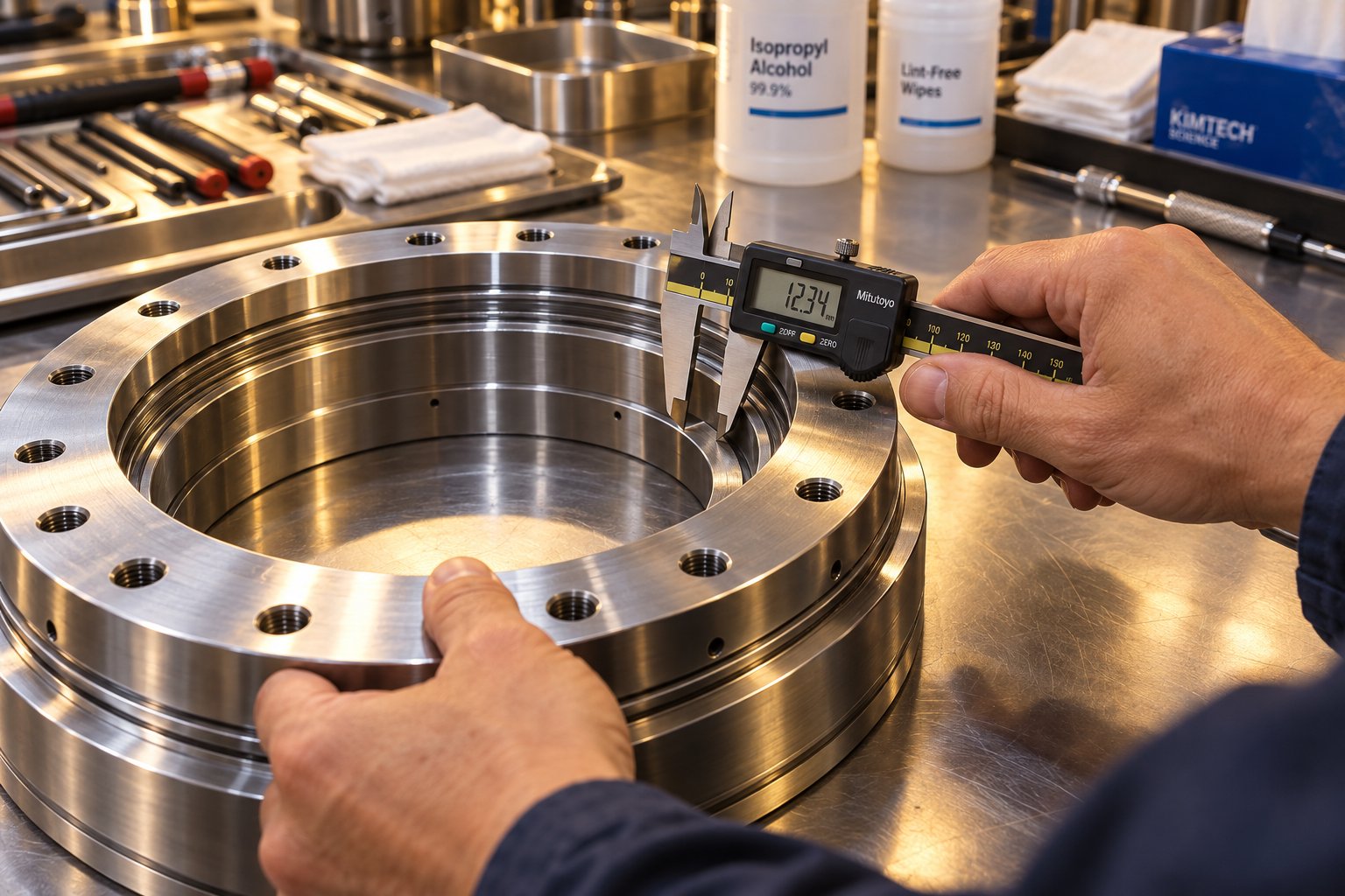
The die is where melt flow distribution is established, and any contamination, wear, or thermal inconsistency inside the die body directly imprints itself onto the circumferential thickness profile. Three often-ignored degradation mechanisms create specific gauge variation signatures that progressively worsen until addressed:
- Die lip buildup from polymer degradation — molten polymer that contacts the die lip surface at elevated temperature for extended periods oxidizes, crosslinks, and forms a carbonaceous residue. This buildup narrows the effective die gap at specific points around the circumference, creating localized thin bands that remain fixed to the die position. On lines running temperature-sensitive resins or operating near the upper end of the processing window, lip buildup can become visible within days.
- Carbon deposit formation in flow channels — degraded polymer accumulates in low-velocity regions of the spiral mandrel channels, behind flow deflectors, and in dead spots within the die body. These deposits restrict flow in the affected channels, starving certain angular positions of melt and producing a repeating circumferential pattern. Unlike lip buildup — which can sometimes be scraped during operation — internal channel deposits require a full die pull and disassembly for thorough removal.
- Die bolt fatigue and hysteresis — die bolts undergo repeated thermal expansion and contraction with every startup, shutdown, and temperature change. Over thousands of cycles, the bolts develop fatigue, lose spring tension, and exhibit hysteresis — meaning a bolt adjusted to a specific position does not return to the same position after being disturbed and re-set. The practical result is that die bolt adjustments become less predictable and less repeatable over time, forcing operators to compensate with larger, more frequent adjustments that introduce their own instability.
A structured blown film die maintenance schedule for gauge control should follow a tiered approach, scaling intervention intensity with inspection frequency. Precision Die Systems emphasizes that implementing a structured maintenance schedule can prolong die life and enhance overall productivity, with regular checks helping to identify wear and tear early and prevent unplanned downtime. The following framework provides a practical starting point that processors can adapt to their specific resins, line speeds, and product mix:
- Daily — visual inspection and surface cleaning. Inspect the die lip for visible buildup, scoring, or polymer drool at the start and end of each production day. Remove any accessible lip residue with approved brass scrapers or non-abrasive tools. Document the locations and severity of any buildup observed — these records reveal patterns over time that indicate developing internal flow restrictions.
- Weekly — die bolt verification and heater zone audit. Verify die bolt positions against documented target settings using calibrated depth gauges or bolt-position indicators. Check every heater band for continuity and compare actual zone temperatures against setpoints using an independent surface thermocouple or calibrated IR pyrometer. A failed heater band may not trigger an alarm if the adjacent zones partially compensate, but it will create a localized cool zone that produces a thickness band.
- Monthly to quarterly — comprehensive die bolt evaluation and air ring inspection. Evaluate die bolt spring tension and replace any bolts showing signs of fatigue, cracking, or permanent set. Clean and inspect the air ring lip, vanes, and plenum for contamination, damage, or corrosion. Verify air ring centering and levelness. Cross-reference the current gauge profile against baseline profiles from the last die cleaning to identify developing trends.
- Semi-annually to annually — full die pull for cleaning, inspection, and refurbishment. Disassemble the die completely. Clean all internal flow channels using chemical cleaning methods compatible with the die metallurgy — mechanical cleaning with abrasive tools should be used carefully to avoid scratching or damaging precision die surfaces. Inspect flow channel surfaces for wear, pitting, or erosion. Verify mandrel centering. Polish die lip surfaces to restore original finish. Replace worn or damaged components. Conduct a full pressure test and dimensional check before reinstallation.
One category of variation drift that catches even experienced operations off guard is seasonal and environmental factors. Ambient temperature shifts between summer and winter alter the cooling air temperature delivered to the air ring — sometimes by 15-20 °C — directly changing the cooling rate and frost line behavior. Plant ventilation changes, such as opening bay doors for warm-weather cooling, introduce asymmetric drafts that create post-die circumferential variation. Humidity shifts affect both cooling efficiency and resin moisture content. None of these factors show up in the die bolt map or the extruder trend data, yet they produce real, measurable gauge drift that processors often attribute to equipment changes when the actual cause is the weather.
The practical countermeasure is straightforward: document ambient conditions alongside gauge profiles. When your spring gauge data starts diverging from your winter baseline, check the cooling air inlet temperature before adjusting die bolts. Consider temperature-controlled makeup air systems for the air ring supply if seasonal variation consistently pushes your product outside tolerance.
Operator Training and Shift-to-Shift Consistency
Imagine two operators — both experienced, both competent — running the same line on consecutive shifts. One adjusts die bolts in 5-degree increments, waits 15 minutes between adjustments, and documents every change. The other turns bolts in quarter-turn increments, waits 5 minutes, and relies on memory. By the end of the week, the die bolt map is a patchwork of conflicting adjustments, and the gauge profile reflects the inconsistency.
This scenario plays out in plants everywhere, and it represents one of the most addressable sources of ongoing variation. Blown film operator training gauge consistency is not about teaching people how extrusion works — most experienced operators already understand that. It is about standardizing how adjustments are made, when measurements are taken, and what gets documented so that every shift builds on the previous one rather than undoing it.
Key elements of an effective operator standardization program include:
- Standardized die bolt adjustment procedures — define the adjustment increment (degrees of rotation or thousandths of an inch), the minimum wait time between adjustments (typically 10-20 minutes for the melt channel to respond fully), and the maximum number of adjustments per shift before escalating to maintenance or engineering. Prevent the common mistake of adjusting multiple bolts simultaneously, which makes it impossible to attribute the resulting profile change to any single correction.
- Measurement frequency protocols — specify how often gauge profiles are taken (e.g., every roll change, every 30 minutes, or continuously via inline scanner), where samples are taken for offline measurement, and how many data points constitute a valid cross-web profile. Consistency in sampling methodology matters as much as the measurement technology itself.
- Documentation requirements — every die bolt adjustment, gauge profile, process parameter change, and resin lot change should be logged with a timestamp and operator identification. This documentation transforms troubleshooting from guesswork into data analysis. When a gauge problem appears on Tuesday's night shift, the ability to review exactly what changed — and when — between Monday's acceptable run and Tuesday's reject is invaluable.
- Shift handoff protocols — outgoing operators should communicate the current gauge status, any adjustments made during the shift, any developing trends observed, and any known issues (e.g., a heater band running slightly low, a die bolt that feels loose). A five-minute structured handoff prevents hours of redundant troubleshooting.
As Swallow Machinery's preventive maintenance guidance stresses, operators and maintenance staff should be trained not only to spot issues but to understand how the system works — because an operator who understands why a die bolt adjustment takes 15 minutes to show its effect will naturally wait the appropriate time, while one who only follows a rule without understanding it will cut corners under production pressure.
Building a Complete Gauge Variation Prevention System
Every section of this guide has addressed a specific piece of the blown film gauge variation puzzle. Taken individually, each piece — resin behavior, extruder stability, die flow distribution, bubble geometry, measurement, automatic control, tolerance benchmarks — provides useful knowledge. Taken together, they form a complete gauge variation troubleshooting workflow that processors can follow from first symptom to sustained resolution.
Here is that workflow consolidated into a systematic sequence:
- Identify the variation pattern. Is the thickness inconsistency circumferential (around the bubble) or machine-direction (along the web length)? Use inline scanner data, offline cross-web profiles, and roll weight trends to characterize what you are seeing.
- Classify the type. If circumferential, is the band fixed to the die or to the room? If machine-direction, does the cycle frequency match screw rotation, heater cycling, feed events, or resin lot changes? Use the four-type classification framework to narrow the source.
- Diagnose the root cause. Follow the diagnostic decision tree for the identified type. Check die bolt map and heater zones for die-fixed circumferential bands. Inspect air ring alignment and ambient conditions for room-fixed or drifting bands. Trend head pressure and melt temperature for machine-direction instability. Compare gauge profiles against roll hardness data for downstream mechanical distortion.
- Implement the correction. Address the confirmed root cause — not the assumed one. Adjust die bolts methodically for die-flow issues. Re-level and clean the air ring for cooling asymmetry. Stabilize extruder feed, thermal control, or mechanical condition for output instability. Realign collapsing frames and verify nip pressure for downstream distortion.
- Measure and verify improvement. Use the appropriate measurement technology — circumferential scanning for die-related corrections, machine-direction trending for extruder-related corrections — to confirm that the fix actually worked and quantify the improvement.
- Establish maintenance protocols for ongoing consistency. Implement the tiered die maintenance schedule. Standardize operator procedures. Document baseline profiles for each product. Schedule preventive maintenance for all components in the variation chain — including the often-deferred extruder screw and barrel replacement that restores output stability long before wear-related surging becomes a chronic gauge problem.
That last point — extruder screw barrel replacement preventive maintenance — deserves emphasis because it is the maintenance item most frequently postponed until the problem becomes undeniable. Screw and barrel wear is gradual, invisible without direct measurement, and easily masked by incremental process adjustments that compensate for the slowly degrading output stability. By the time an operator notices machine-direction gauge bands that resist all other corrections, the clearance may have doubled from its original specification, and thousands of hours of sub-optimal production have already passed. For processors sourcing replacement barrels to restore output consistency as part of their preventive maintenance program, NANHAIYA's custom and replacement single screw barrels for film extrusion lines provide options matched to specific extruder dimensions, resin requirements, and wear-resistance needs — ensuring that the replacement component delivers the tight tolerances needed for stable melt delivery from day one.
Environmental monitoring rounds out the prevention system. Track ambient temperature and humidity alongside gauge data. Correlate seasonal shifts with profile changes. Integrate cooling air temperature measurement into your process monitoring dashboard. These environmental variables are invisible to operators focused on the die and extruder but produce real variation that accumulates silently until it crosses a tolerance boundary.
Gauge variation control is a system-level discipline spanning resin selection, extruder maintenance, die care, process optimization, measurement technology, automatic control, and operator consistency — no single adjustment solves it, and no single neglected element leaves it unaffected.
The processors who consistently produce the tightest gauge films in the industry are not the ones with the most expensive equipment. They are the ones who treat thickness control as an integrated system — where every component from the feed hopper to the winder is maintained, monitored, and operated with the same discipline. This guide has mapped every element of that system. The competitive advantage belongs to those who implement it.
Frequently Asked Questions About Blown Film Gauge Variation
1. What are the main causes of blown film gauge variation?
Blown film gauge variation stems from four primary source categories. Die-related causes include uneven die gaps, blocked flow channels, and temperature asymmetry across the die body, producing circumferential thick-thin bands fixed to the die position. Post-die causes such as air ring misalignment, IBC imbalances, and ambient drafts create circumferential bands that drift or rotate relative to the die. Machine-direction variation originates upstream from extruder output surging, screw and barrel wear, back pressure changes, or resin viscosity inconsistency. Finally, downstream mechanical issues like collapsing frame misalignment and nip roll pressure variation can distort the film after it has already formed. Resin rheology also plays a significant role — polymers with low melt strength like LLDPE amplify existing process asymmetries more than high-melt-strength resins like LDPE. Proper diagnosis requires classifying the pattern type before attempting corrections.
2. How do you convert between mil, gauge, and micron for plastic film thickness?
The fundamental equivalence is 1 mil = 100 gauge = 25.4 microns = 0.0254 mm. To convert mils to gauge, multiply by 100 (e.g., 1.5 mil = 150 gauge). To convert microns to gauge, divide by 0.254 (e.g., 50.8 microns = 200 gauge). To convert gauge to microns, multiply by 0.254. Note that plastic film gauge differs from wire or sheet metal gauge — in film, higher gauge numbers mean thicker material, which is the opposite of the metal convention. Always state units explicitly on specifications and purchase orders, as confusing 'mil' with 'millimeter' creates a nearly 40-fold thickness error. ASTM D6988 and ISO 4593 govern the standardized measurement protocols used across the industry.
3. How does automatic gauge control work in blown film extrusion?
Automatic gauge control (AGC) uses a closed-loop system where an inline thickness scanner continuously measures the film profile, a controller compares measurements against target values, and actuators apply localized corrections. The four main AGC methods are segmented air ring lip control (adjusting external cooling airflow at individual circumferential positions), segmented air ring plenum control (modulating air volume to discrete plenum zones), IBC-based control (adjusting internal bubble cooling), and automatic die bolt control (using thermal or mechanical actuators to adjust die gap). Segmented air ring systems respond within seconds and handle post-die circumferential variation effectively. Automatic die bolt systems address variation at its source but respond in minutes due to polymer thermal inertia. Modern lines often combine both approaches — die bolts for slow, persistent baseline corrections and air ring segments for faster transient adjustments. AGC effectiveness depends entirely on accurate inline measurement and cannot compensate for severe upstream extruder output instability.
4. How does post-consumer recycled resin (PCR) affect blown film thickness control?
Post-consumer resin introduces several gauge control challenges because it originates from diverse waste streams with variable composition. Batch-to-batch melt flow index swings alter how the polymer distributes through the die and responds to bubble inflation. Contamination from residual inks, adhesives, and mixed polymer fractions creates micro-heterogeneities in the melt that produce noisy, unstable gauge readings. Degradation and crosslinking from repeated thermal cycling cause inconsistent melt strength, while inadequate drying releases moisture and volatiles that trigger melt surging and bubble instability. PCR-related variation primarily appears as machine-direction instability rather than fixed circumferential bands. Processors running higher PCR percentages need tighter upstream controls — consistent melt temperature, thorough distributive mixing, pre-drying protocols, and well-maintained extruder screws and barrels such as precision-manufactured replacement components from suppliers like NANHAIYA (nhyscrews.com) — to maintain acceptable gauge uniformity.
5. What is an acceptable gauge tolerance for blown film by application?
Acceptable blown film gauge tolerance varies significantly by end-use application. Food packaging and lamination films typically require the tightest tolerances at plus or minus 3% to 5% because high-speed form-fill-seal and laminating equipment demands consistent film feeding, sealing, and barrier performance. Shrink film generally allows plus or minus 5% to 7% since uneven thickness causes non-uniform shrink behavior. Stretch and cling films typically fall within plus or minus 5% to 8%. Retail carrier bags and heavy-duty sack films tolerate wider bands at plus or minus 7% to 10% because their performance depends more on minimum gauge at the weakest point than on overall uniformity. Agricultural mulch film permits the widest tolerances at plus or minus 8% to 12%. These benchmarks matter economically because wider variation forces processors to run heavier average thickness to ensure minimum specification is met everywhere, creating costly material giveaway on every roll produced.
Written by
Nanhaiya Technical Team
Zhoushan Nanhaiya Plastic Machinery Co., Ltd.
The Nanhaiya technical team supports screw and barrel manufacturing projects through application review, technical communication, custom manufacturing coordination, and production and quality control.
Discuss Your Application
Related Articles
More insights on screw barrel technology and plastics processing.

Your Extruder Feeding Instability Isn't Random — Here's Why
Oct 22, 2026
Extruder feeding instability causes surging output and scrap. Learn the 6 root causes, polymer-specific fixes, wear diagnostics, and preventive protocols.
Read Article
Parallel Twin Screw Extruder for Compounding Demystified: Lab to Line
Oct 21, 2026
Learn how a parallel twin screw extruder for compounding works—from screw element design and zone configuration to lab-to-production scale-up and process optimization.
Read Article
Twin Screw Extruder for PVC: The Setup Mistake Draining Profit
Oct 21, 2026
Learn how to match twin screw extruder configurations to PVC applications. Covers conical vs parallel, counter-rotating vs co-rotating, wear management, and troubleshooting.
Read ArticleLooking for something else?
Search by material, symptom or product and jump straight to the relevant page.
These are navigation suggestions based on keyword matching — not a quotation, not a delivery commitment, and not a substitute for engineering review. Final specification is confirmed by our engineers against your drawings and processed material.
Need help with screw barrel selection?
Share your machine model, processed material and application. Our team can help with pricing and technical support.