

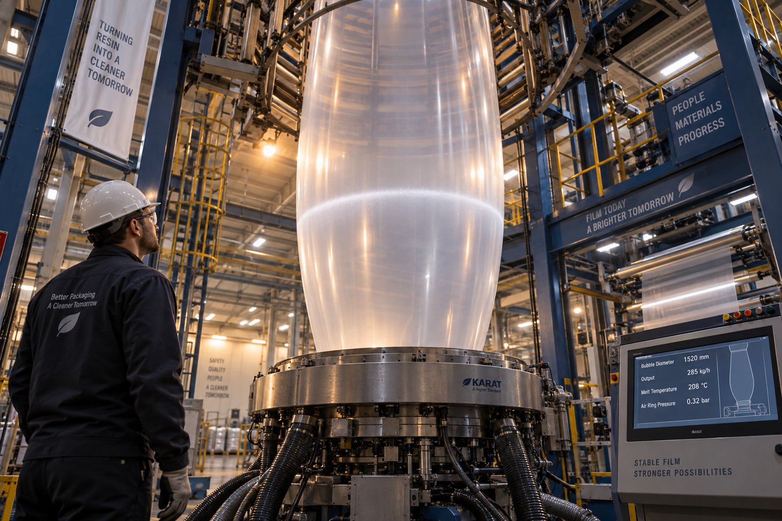
Understanding Blown Film Extrusion Troubleshooting
Blown film extrusion troubleshooting is the systematic process of identifying, diagnosing, and correcting production problems that occur anywhere along a blown film line — from the extruder hopper all the way to the winder. It is a structured discipline, not guesswork, and it starts the moment an operator spots a symptom like haze, wrinkles, gauge variation, or an unstable bubble.
What Blown Film Extrusion Troubleshooting Really Means
Imagine you're standing on the production floor and you notice the bubble breathing — expanding and contracting in a rhythmic pulse. Your instinct might be to reach for the air ring controls immediately. But effective blown film line defect diagnosis demands a different reflex. You first observe the symptom, determine its pattern and location, then trace it back through the line to find the root cause before touching a single setting.
Every defect your line produces is a message. Gauge bands running in the machine direction point you toward the extruder or die. Thickness variations across the lay-flat width suggest air ring or die gap issues. Random gels and specks flag contamination or resin quality problems. When you learn to read these signals, you stop chasing symptoms and start solving problems.
Effective troubleshooting starts with understanding what you observe on the line before changing any settings.
Why a Systematic Approach Saves Time and Material
Unresolved defects carry a steep price tag. Scrap rates climb, off-spec rolls pile up in the warehouse, and unplanned downtime eats into delivery schedules. High-speed extrusion lines operate with multiple interacting variables, where even small fluctuations can escalate into production inefficiencies. A single uncorrected gauge band can generate thousands of pounds of rejected film before anyone identifies the source. A systematic approach — isolating one variable at a time, following the melt path, and documenting every change — prevents the costly cycle of random adjustments that often make problems worse.
How This Guide Is Organized for the Production Floor
This blown film extrusion troubleshooting guide is built around what you actually see on your line. Rather than organizing content by theory or equipment catalogs, every section leads with the symptom — the visual or measurable defect an operator encounters during a shift. From there, you'll follow a logical path through each line section, from screw and barrel through die, air ring, bubble geometry, collapsing frame, nip rolls, and winder. Each defect is paired with ranked root causes and specific corrective actions, not vague suggestions like "adjust temperature," but clear direction on which zone, which way, and why.
The sections ahead also cover territory most resources skip entirely: how process variables interact and trigger chain reactions, how to handle die lip buildup and purging decisions, how to diagnose mechanical wear versus process drift, and how to reduce the scrap that piles up during startups and shutdowns. Whether you're troubleshooting blown film problems for the first time or refining a process you've run for years, the goal is the same — faster answers, less waste, and a more stable line.
The real question, though, is where exactly on your line a given defect originates — and that requires a reliable diagnostic method.
A Systematic Diagnostic Method for Blown Film Lines
A defect on your lay-flat film is not just a quality issue — it is a clue. The orientation, frequency, and position of that defect tell you which section of the line to investigate first. Without a reliable blown film defect classification method, operators end up adjusting parameters at random, often compounding the original problem with new ones. A structured diagnostic approach eliminates that cycle and gets you to the root cause faster.
Classifying Defects by Direction and Pattern
Every defect on a blown film line falls into one of four pattern categories, and each category points you toward a different part of the equipment. Machine direction (MD) defects — streaks, lines, or thickness bands running continuously along the length of the film — typically originate in the extruder, screw, or die. These are stationary relative to the die, meaning the problem stays in the same angular position as the bubble rotates (if your die rotates) or remains fixed on the lay-flat.
Cross direction (CD) defects show up as variations across the film's width. Uneven gauge profiles from one edge to the other, or localized thin spots at specific clock positions, usually trace back to the air ring, die gap uniformity, or IBC airflow balance. The distinction between machine direction vs cross direction film defects is the single most useful first step in any diagnosis.
Random defects — gels, black specks, fisheyes, or contamination marks scattered unpredictably — point toward material quality, degraded polymer, or contamination somewhere in the melt stream. Periodic defects that repeat at regular intervals often indicate a mechanical source: a damaged screw flight, a worn bearing, or a roller with a flat spot. Counting the repeat distance and matching it to component circumferences can pinpoint the culprit with surprising precision.
| Defect Pattern | Description | Most Likely Line Section | Examples |
|---|---|---|---|
| Machine Direction (MD) | Continuous streaks or bands running along film length | Extruder, screw, die, die lips | Die lines, gauge bands, flow lines |
| Cross Direction (CD) | Variations across the film width at fixed positions | Air ring, die gap, IBC system | Uneven thickness profile, localized thin spots |
| Random | Unpredictable defects with no repeating pattern | Resin quality, contamination, degraded polymer | Gels, black specks, fisheyes, foreign particles |
| Periodic | Defects repeating at regular, measurable intervals | Mechanical components (screw, rollers, gears) | Surging marks, repeating thickness bumps, roller marks |
Following the Melt Path From Hopper to Winder
A blown film diagnostic flowchart by line section gives you a logical sequence for narrowing down problems. Think of it as following the polymer's journey — every stage it passes through is a potential origin point for defects. When you work through the line systematically instead of jumping to the most obvious or most accessible adjustment, you avoid missing upstream causes that would make downstream corrections pointless.
Before making any changes to your process, walk through this diagnostic sequence:
- Extruder and screw — Check melt pressure stability, motor load, and barrel temperature profiles. Look for surging, pressure fluctuations, or signs of unmelted resin.
- Die and die lips — Inspect for buildup, scoring, or uneven flow. Confirm die bolt temperatures are uniform and die gap is consistent around the circumference.
- Air ring and IBC — Verify cooling air velocity balance, air ring centering, and IBC pressure stability. Uneven cooling is one of the most common sources of gauge variation and bubble instability.
- Bubble geometry — Observe frost line height, blow-up ratio consistency, and bubble shape symmetry. An asymmetric bubble reveals an imbalance you need to trace upstream.
- Collapsing frame — Check frame alignment, guide roller condition, and the angle at which the bubble enters the collapsing tent. Misalignment here creates wrinkles that look like a die or cooling issue.
- Nip rolls — Confirm roll parallelism, nip pressure uniformity, and surface condition. Worn or uneven nip rolls introduce creases and stretching patterns into the lay-flat.
- Winder — Evaluate tension control, lay-on roll pressure, and roll alignment. Many wrinkle and blocking complaints that seem to originate upstream are actually winder-related.
This sequence mirrors the melt path itself. Starting at the extruder and working downstream ensures you catch root causes before they cascade into secondary symptoms that obscure the real problem.
The One-Variable Rule for Safe Adjustments
Here is where discipline separates experienced operators from everyone else. When you isolate variables on a blown film line, you change exactly one parameter at a time, then observe and document the result before touching anything else. It sounds simple, but production pressure constantly tempts operators to adjust melt temperature, air ring speed, and line speed simultaneously — making it impossible to know which change actually helped or hurt.
Each adjustment needs enough time to stabilize. A melt temperature change can take 15 to 20 minutes to fully propagate through the barrel and die. An air ring adjustment shows its effect on the bubble within seconds, but its impact on gauge and film properties may not be measurable until several rolls have been wound. Patience is not optional — it is part of the method.
Change one variable, wait for stabilization, measure the result, and document everything before making the next move.
A simple log — recording the time, the parameter changed, the direction and magnitude of the change, and the observed outcome — transforms scattered adjustments into a repeatable diagnostic record. Over weeks and months, that log becomes one of the most valuable resources on your production floor, revealing patterns that no single troubleshooting session can uncover.
With a reliable method for classifying defects and tracing them through the line, the next step is connecting specific symptoms to their most likely causes — and knowing exactly what corrective action to take for each one.
Common Film Defects With Causes and Specific Fixes
Knowing how to classify defects and trace the melt path gives you a framework — but when you're staring at a defect on the film right now, you need specific answers. What's causing it? What should you adjust, in which direction, and where? The table below is built around exactly that need: you start with what you see, then work through ranked root causes and targeted corrective actions. No vague advice, just directional guidance tied to a specific zone on your line.
Gauge Variation and Thickness Inconsistency
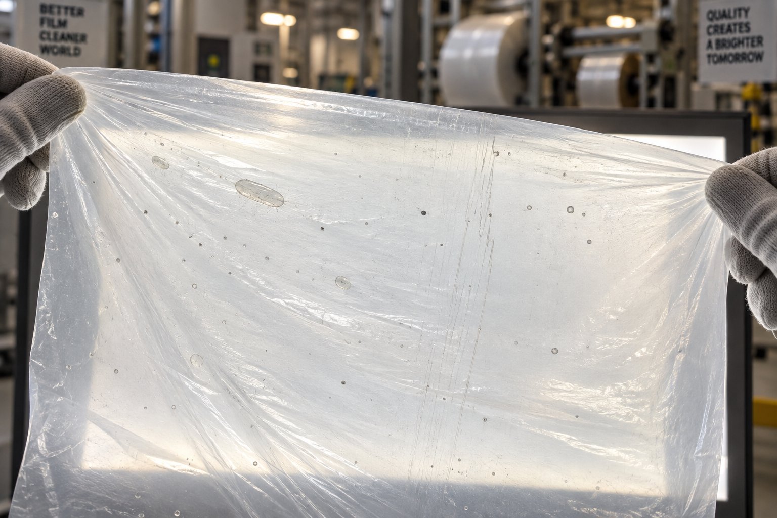
Blown film gauge variation causes and solutions top the list of operator concerns because thickness inconsistency affects everything downstream — bag strength, seal integrity, print registration, and material cost. When gauge bands appear in the machine direction, the problem almost always lives in the die or die lips. A dirty or misadjusted die lip creates a localized flow restriction that stamps a thin or thick streak into every meter of film. Cross-direction thickness variation, on the other hand, usually traces back to uneven cooling. If your air ring is off-center or has blocked supply lines, one side of the bubble cools faster, freezes earlier, and locks in a different thickness than the opposite side. Always verify die gap uniformity and air ring centering before adjusting temperature profiles — those two mechanical checks resolve the majority of gauge complaints.
Haze and Poor Optical Clarity
Figuring out how to fix haze in blown film extrusion starts with identifying whether the haze originates on the film surface or inside a coextruded structure. Surface haze — the more common variety — is typically caused by mild melt fracture, where the polymer skin ruptures microscopically as it exits the die and gets hit with cooling air. A simple diagnostic trick from Plastics Technology: immerse a film sample in water. Surface melt fracture disappears because water fills the micro-roughness, while interfacial instability between coex layers remains visible. Raising the melt temperature by 5-10 degrees Fahrenheit in the die zones reduces shear stress at the lip and often eliminates surface haze. If temperature alone doesn't solve it, check for non-uniform die heating — a failed heater band or drifting thermocouple on one zone can create a localized cold spot that triggers melt fracture in that sector only.
For coextruded films, haze from interfacial instability requires a different approach entirely. Matching the viscosities of adjacent layers — by adjusting individual extruder temperature profiles until backpressures are closer together — addresses the root cause rather than masking it.
Wrinkles and Blocking in Finished Film
Blown film wrinkles and crease troubleshooting is tricky because wrinkles can originate anywhere from the bubble to the winder, yet they all show up in the same place — the finished roll. Edge wrinkles typically point to a collapsing frame angle that's too steep, forcing excess material to bunch at the fold. Center wrinkles often mean the opposite — the collapsing angle is too shallow. Lightning-bolt wrinkles running diagonally across the lay-flat usually indicate nip roll problems: uneven pressure, diameter variation side-to-side, or misalignment between the rubber and chrome rolls.
Blocking — where layers of wound film stick together and resist unwinding — is a separate issue that often gets blamed on the extrusion process when it's actually a winding or additive problem. Excessive winding tension compresses warm film layers together before anti-block additives have migrated to the surface. Over-treated film from corona treatment amplifies this effect by raising surface energy beyond what slip additives can counteract. Reducing winding tension and verifying that treatment levels match the downstream application's actual requirements are the fastest fixes.
Bubble instability causes in blown film — the rhythmic breathing or side-to-side sway that makes operators nervous — often trace back to IBC control issues, inconsistent cooling air temperature, or melt pressure fluctuations from the extruder. And melt fracture sharkskin in blown film, that rough sawtooth texture visible on the film surface, responds to raising die lip temperature, widening the die gap, or as a last resort, adding a fluoropolymer processing aid to reduce friction at the die wall.
The following table consolidates these defects — and several more — into a single quick-reference matrix you can use right on the production floor.
| Symptom | Possible Root Causes (Ranked by Likelihood) | Specific Corrective Action | Zone / Location |
|---|---|---|---|
| Gauge bands / uneven thickness | 1. Dirty or misadjusted die lips | Clean (shim) die lips at localized lines; re-gap die to uniform clearance | Die lips |
| 2. Air ring off-center or blocked airflow | Re-center air ring; inspect for blocked plenums, dirty screens, crimped supply hoses | Air ring / IBC | |
| 3. Non-uniform die heating | Check all die zone heaters and thermocouples; replace failed elements | Die body zones | |
| Haze / poor optical clarity | 1. Melt temperature too low (surface melt fracture) | Raise melt temperature 5-10 °F; increase die lip zone temperature | Die zones / die lip heaters |
| 2. Non-uniform extrudate quenching | Verify air ring centering; check chiller temperature consistency; inspect IBC tubes for leaks | Air ring / IBC / chiller | |
| 3. Interfacial instability (coex only) | Adjust extruder profiles to match adjacent-layer viscosities; match backpressures closer together | Individual extruder barrels | |
| Wrinkles before nip roll | 1. Bubble instability / breathing | Stabilize output; verify IBC sensor position relative to frost line; check chilled air temperature consistency | Extruder / IBC / air ring |
| 2. Collapsing frame angle incorrect | Decrease angle for edge wrinkles; increase angle for center wrinkles | Collapsing frame | |
| 3. Nip roll misalignment or pressure variation | Check nip roll diameter uniformity side-to-side; verify parallel alignment and even nip pressure | Nip rolls | |
| Melt fracture / sharkskin | 1. Excessive shear stress at die exit | Raise die lip temperature; activate lip heaters if equipped | Die lip zone |
| 2. Die gap too narrow | Increase die gap (typical LLDPE range: 80-100 mils); note impact on drawdown capability | Die lips | |
| 3. Resin rheology limitations | Add fluoropolymer processing aid (PPA) at 500-1000 ppm; or blend in higher-MFI resin to reduce viscosity | Blending / feed system | |
| Film blocking in rolls | 1. Winding tension too high | Reduce winding tension; allow film to cool before applying full tension | Winder |
| 2. Corona treatment level excessive | Reduce treatment to minimum level required for downstream application | Treater station | |
| 3. Insufficient anti-block additive | Increase anti-block additive concentration; verify masterbatch feeder accuracy | Feed system / blender | |
| Gels, black specks, carbon contamination | 1. Degraded polymer on screw, barrel, or die surfaces | Purge with high-MFI resin or commercial purge compound; if persistent, disassemble and clean | Extruder / screen changer / die |
| 2. Worn or damaged extruder screw | Inspect and measure screw flight dimensions; replace if clearance exceeds tolerance | Extruder screw / barrel | |
| 3. Contamination in resin supply | Check material handling system for angel hair, cross-contamination, or foreign particles | Hopper / conveying lines / silos | |
| Bubble instability / breathing | 1. IBC control malfunction or sensor misplacement | Verify IBC supply/exhaust tubes are seated; reposition sensors near frost line height | IBC system |
| 2. Inconsistent cooling air temperature | Check blower stability and chiller setpoint; inspect cooling coils for ice buildup or fouling | Air ring / blower / chiller | |
| 3. Melt pressure surging from extruder | Check for screw wear, inconsistent feeding, or bridging in hopper; stabilize extruder RPM and backpressure | Extruder / feed throat |
This matrix covers the defects operators encounter most frequently, but every blown film line has its own personality. Resin formulation, layer structure, die design, and downstream equipment all influence which root causes dominate on your specific line. The key habit is to start with the symptom, consult the most likely causes in order, and work through corrections one variable at a time — exactly the method outlined in the previous section.
Fixing a single defect, however, rarely happens in isolation. Adjusting one parameter to solve a gauge problem can shift your frost line, change clarity, or alter mechanical properties in ways you didn't anticipate. Understanding these chain reactions is what separates a quick fix from a truly stable process.
How Process Variables Interact During Troubleshooting
You've just solved a haze problem by raising melt temperature — and ten minutes later, the bubble starts swaying. Or you bumped up air ring velocity to stabilize gauge, only to find that your frost line climbed three inches and your film clarity dropped. Sound familiar? Blown film process variable interaction effects catch operators off guard because every parameter on your line is connected to several others. Adjusting one knob doesn't just change one outcome — it triggers a chain reaction across multiple film properties simultaneously.
Understanding these interactions is what separates a stable correction from a frustrating whack-a-mole session where fixing one defect creates two new ones. Let's walk through the most critical relationships you'll encounter.
How Cooling Changes Affect Frost Line and Gauge
Air ring cooling velocity and frost line height are directly linked: push more air at the bubble, and the frost line drops closer to the die. Reduce the air, and the frost line climbs higher. That relationship seems straightforward — but the secondary effects are where things get complicated.
When you increase cooling velocity to bring the frost line down and speed up crystallization, you're also changing the gauge profile. Faster cooling locks in the film's thickness before the melt has fully distributed around the circumference. Any minor flow imbalance from the die — something that a slower cooling rate would have allowed the melt to self-correct — now becomes a permanent gauge band frozen into the film. You'll notice this especially with LLDPE resins, where a lower frost line can produce tighter, more visible gauge bands that weren't apparent at slower cooling rates.
Clarity takes a hit as well. Rapid quenching favors smaller crystallites, which generally improves transparency in some resins, but it also increases surface roughness if the melt hasn't fully relaxed before contact with the cooling air. The result can be a film that meets gauge spec but fails optical requirements — a trade-off that's invisible if you only check one property after making the adjustment.
Reducing cooling velocity has its own cascade. A higher frost line gives the melt more time to orient in the machine direction, increasing MD shrinkage potential. Bubble stability can also suffer because a taller molten zone is more susceptible to drafts and vibration from the plant environment.
Melt Temperature Trade-offs Across Film Properties
Raising melt temperature is one of the most common fixes for surface haze and melt fracture — and it works, because a hotter melt has lower viscosity and experiences less shear stress at the die lip. The melt temperature effect on blown film clarity is real and significant. But every degree you add on the melt side costs you something on the mechanical and stability side.
A hotter melt is weaker. It sags more easily under its own weight between the die exit and the frost line, which makes the bubble geometry harder to control. Bubble stability decreases because the molten zone is softer and more responsive to air currents, IBC pressure fluctuations, and even vibrations transmitted through the tower structure. If you're running a high blow-up ratio, the combination of higher melt temperature and aggressive TD stretching can push the bubble into instability territory very quickly.
There's also a downstream effect most operators don't immediately connect. Higher melt temperatures mean more thermal energy that the air ring has to remove. If your cooling capacity is already near its limit, raising melt temperature can push the frost line up, slow the line down, and reduce throughput — the exact opposite of what you intended. The film's crystallinity also changes: a hotter melt that cools at the same rate produces a different crystal structure than a cooler melt, shifting mechanical properties like stiffness, tear resistance, and puncture strength in ways that may not show up until the customer tests the finished product.
Blow-Up Ratio and Line Speed Chain Reactions
Increasing the blow-up ratio (BUR) stretches the film more in the transverse direction, improving TD properties like tear strength and stiffness across the web. But that improvement comes at a cost in the machine direction. Research on LLDPE films has demonstrated that as crystal orientation increases, MD tear strength drops substantially — and the rate of that decline depends on the resin type. A study published in Polymers found that at a given crystal orientation level, butene-based LLDPE retained only 47% of its intrinsic MD tear strength, while octene-based LLDPE held onto 77%. This means how blow-up ratio affects film properties isn't just a matter of geometry — it depends heavily on your resin selection.
Higher BUR also thins the film at the edges of the lay-flat because the bubble circumference stretches the melt more aggressively at the fold points. If you increase BUR without compensating with die gap or air ring adjustments, you'll see thinner edges, more edge trim waste, and potential seal failures in downstream converting.
Line speed changes create an even broader chain reaction. Increasing line speed reduces the time the film spends in the cooling zone, which raises the frost line and decreases crystallinity. Lower crystallinity means softer, more flexible film — sometimes desirable, sometimes a problem. Mechanical properties shift across the board: tensile strength, modulus, tear resistance, and elongation all respond to crystallinity changes. Faster line speed also reduces the effectiveness of corona treatment if your treater output doesn't scale proportionally, leading to adhesion complaints at the printer or laminator.
Never evaluate a process change by one property alone — always check the full set of affected variables before confirming the adjustment.
The interaction matrix below maps these relationships in one view. Use it as a quick reference whenever you make a primary adjustment — scan across the row to see what else you need to monitor.
| Primary Adjustment | Frost Line Height | Gauge Uniformity | Optical Clarity | Bubble Stability | MD Tear Strength | TD Tear Strength | Throughput |
|---|---|---|---|---|---|---|---|
| Air ring velocity ↑ | ↓ | Risk of gauge bands ↑ | Can ↓ (surface roughness) | ↑ (shorter molten zone) | Minimal change | Minimal change | Can ↑ (faster cooling) |
| Melt temperature ↑ | ↑ | Slight risk ↑ (sag effects) | ↑ (less melt fracture) | ↓ (weaker melt strength) | Can ↓ (orientation shift) | Can ↓ (orientation shift) | Can ↓ (cooling limited) |
| Blow-up ratio ↑ | ↑ (larger bubble surface) | Thin edges ↑ | Variable (resin dependent) | ↓ (larger molten surface) | ↓ (more TD orientation) | ↑ (more TD orientation) | No direct change |
| Line speed ↑ | ↑ (less cooling time) | Risk ↑ (less stabilization time) | Variable | ↓ (less cooling time) | ↓ (higher MD orientation) | Can ↓ (less crystallinity) | ↑ |
| Die gap ↑ | Minimal change | Can ↑ (more uniform flow) | ↑ (less shear at lip) | ↑ (thicker melt curtain) | Minimal change | Minimal change | ↑ (lower diehead pressure) |
This matrix is not exhaustive — your specific resin, die design, and cooling configuration will shift some of these relationships. But the principle holds universally: every adjustment has secondary effects, and ignoring them is how a solved problem becomes two unsolved problems. Build the habit of scanning across this row-by-row map after every change, and you'll catch cascading issues before they reach the winder.
Some of the trickiest process disturbances, though, don't originate from parameter changes at all. They come from material building up where it shouldn't — on die lips, in dead spots, and along barrel walls — silently degrading until contamination becomes impossible to ignore.
Die Lip Buildup and Purging Best Practices
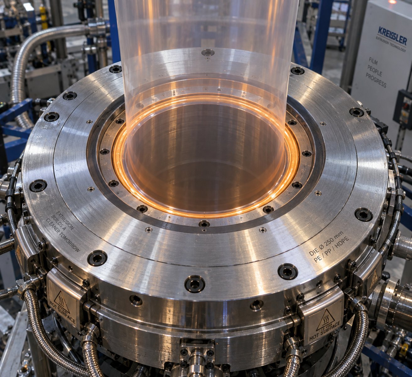
That slow, creeping contamination problem mentioned at the end of the last section? On a blown film line, it most often shows up as die lip buildup — a thin, crusty layer of degraded polymer that accumulates right at the exit point of the die. It starts out invisible. Then it becomes a faint yellowish ring. Eventually, chunks break free and streak through the bubble as carbon trails, gels, or black specks that ruin roll after roll of finished film. Industry data suggests that nearly 30% of production interruptions in extrusion processes can be attributed to die buildup — making it one of the most costly and underappreciated sources of unplanned downtime.
Understanding the blown film die lip buildup causes and knowing when to purge versus when to pull the die apart for a full cleaning can save you hours of lost production every week.
Recognizing Die Lip Buildup and Carbon Contamination
Die lip buildup forms when a thin film of polymer oxidizes and degrades on the die face. The polymer at the very edge of the lip moves slowly — sometimes it barely moves at all — and that stagnant material bakes under continuous exposure to heat and air. Over time, it darkens, hardens, and grows outward from the lip edge. You'll notice it first as a slight discoloration around the die exit, then as faint die lines in the film that weren't there during startup.
Carbon contamination gels in blown film follow a predictable escalation pattern that operators can learn to read. Here's what to watch for as buildup progresses:
- Early stage: Occasional small gels appear in the film — easy to miss unless you're inspecting samples against a light source. Die lines may appear faint or intermittent.
- Intermediate stage: Gel frequency increases noticeably over a shift. Black specks become visible to the naked eye. Die lines that previously stayed in one position begin shifting — a sign that buildup is breaking loose and reattaching at different spots on the lip.
- Advanced stage: Carbon trails — dark streaks running continuously in the machine direction — appear in the bubble. Large gel clusters or "curtains" of degraded material periodically release into the melt stream, causing defect bursts that may trigger automatic inspection alarms.
The key diagnostic clue is the trend. A single gel in a roll is not necessarily cause for alarm. But when you notice gel counts climbing steadily from shift to shift, or when die lines that were previously stable start wandering, your line is telling you that degraded material is accumulating faster than the melt stream can carry it away.
Purging Procedures That Minimize Downtime
Knowing how to purge a blown film extruder properly is the difference between a 30-minute maintenance stop and a full-day die teardown. The goal of purging is to flush degraded polymer from the screw, barrel, screen changer, and die passages before contamination reaches the level where mechanical cleaning becomes unavoidable.
You have two main purging options: high-MFI (melt flow index) purge resin and commercial purge compounds. High-MFI resin — typically a fractional melt HDPE or a high-flow LDPE — works by flooding the system with a low-viscosity melt that displaces stagnant material through sheer volume. It's inexpensive and effective for routine maintenance purges where buildup is still in the early stages. The drawback is that it lacks the chemical or mechanical scrubbing action needed to dislodge hardened carbon deposits.
Commercial purge compounds take it a step further. Chemical purge grades use reactive ingredients that soften and lift baked-on degradation from metal surfaces. For spiral dies specifically, purging experts recommend raising die temperatures to a minimum of 500 °F when using a chemical purge, extruding the compound until only purge material exits the die, then slowing screw RPM to a crawl and allowing a 30-minute soak period. Keeping the screw turning during the soak ensures fresh purge material continuously contacts contaminated surfaces inside the die.
Regardless of which purge method you choose, follow these guidelines for the best results:
- Purge temperature: Run 20-40 °F above your normal production temperature to reduce melt viscosity and improve the purge material's ability to reach dead spots. For chemical purge compounds, follow the manufacturer's recommended temperature range — going too high can degrade the purge itself.
- Evaluating purge effectiveness: Before resuming production, extrude production resin at normal conditions and inspect the first several feet of film against a bright backlight. If gels or discoloration persist, run a second purge cycle. Do not restart production until film samples are visually clean.
- Transition back to production: After purging, ramp production resin through gradually. The first few minutes of output after a purge often contain residual purge compound — discard this material rather than winding it into saleable rolls.
When Die Cleaning Cannot Be Avoided
Purging is powerful, but it has limits. There are situations where no amount of purging will restore clean film, and the only option is a full die teardown and manual cleaning. Recognizing when you've crossed that line prevents wasted purge material and lost production time spent on a procedure that won't work.
A full die disassembly and cleaning is necessary when you observe any of the following:
- Persistent die lines that remain in the same angular position even after thorough purging — indicating physical damage or hardened deposits in the die land or lip area
- Carbon contamination that returns to pre-purge levels within hours of resuming production
- Visible buildup on the die face that cannot be removed with brass scrapers during a running wipe
- Gel counts that fail to decrease after two consecutive purge cycles using a commercial compound
- Evidence of die lip damage — nicks, scratches, or corrosion — that creates permanent flow disruption
Preventive die lip cleaning intervals vary by resin and operating temperature, but a practical starting point for most polyethylene blown film operations is a scheduled external lip wipe with brass tools every 8-12 hours of continuous production, and a full internal die cleaning every 4-6 weeks. Lines running higher-temperature resins, recycled content, or heavily filled compounds will need shorter intervals. Tracking gel counts over time lets you fine-tune the schedule to your specific operation rather than relying on generic recommendations.
Keeping the die clean protects film quality, but contamination isn't the only silent threat to your line's performance. Gradual mechanical wear in the extruder itself — on the screw flights and barrel wall — can mimic process problems and resist every troubleshooting adjustment you throw at it.
Screw and Barrel Wear Diagnostics for Film Lines
You've optimized your melt temperature, rebalanced your air ring, verified die gap uniformity, and run two purge cycles — yet the bubble still surges, output keeps falling short, and gels won't go away. At some point, the process stops being the problem. The hardware is. Extruder screw barrel wear symptoms on a blown film line are deceptive because they develop so gradually that operators compensate instinctively — bumping RPM up a few turns here, nudging a zone temperature there — without realizing they're masking a mechanical decline that no process adjustment can fix.
Knowing how to diagnose screw wear on a film extrusion line is essential because misdiagnosing a wear problem as a process problem wastes hours of troubleshooting effort and generates mountains of scrap in the meantime. The signs are specific, measurable, and — once you know what to look for — surprisingly clear.
Symptoms That Point to Mechanical Wear Not Process Settings
Screw and barrel wear doesn't announce itself with a single dramatic failure. It whispers through your process data over weeks and months. Here are the signals that separate a worn extruder from a poorly tuned one:
Gradual output decline at constant RPM. This is the hallmark symptom. If you're running the same resin at the same screw speed and your throughput is 10-15% lower than it was six months ago, the screw flights have lost enough material to allow polymer to leak back over the flights instead of being pushed forward. According to a predictive maintenance analysis from MachineCDN, output dropping below 85% of the rated capacity at a given RPM places the screw in "replace" territory — a threshold that holds reliably across most single-screw film extrusion applications.
Rising melt temperature at constant setpoints. A worn screw does less work on the polymer through conductive and compressive melting, so the barrel heaters work harder to compensate. You'll see heater duty cycles creeping from their normal 40-70% range toward 80-90%. Simultaneously, shear heating becomes erratic because the wider flight clearance allows inconsistent melt shearing. If your actual melt temperature consistently reads more than 15 °F above your setpoint — and your thermocouples are verified — the screw-barrel fit has degraded past the point where temperature control can compensate.
Visible surging in the bubble. You've already addressed the process-side causes of surging from the diagnostic method in earlier sections — feed consistency, melt pressure stability, and cooling balance. When surging persists despite all of those being optimized, the extruder itself is the source. Worn flight clearances create an unstable solid bed, causing pressure pulses in the melt stream that show up as rhythmic thickness variations in the bubble and a melt pressure fluctuation exceeding ±50 PSI during what should be steady-state operation.
Unmelt gels in the film. These are distinctly different from the carbon gels and degradation specks covered in the previous section on die lip buildup. Unmelt gels are unmelted or partially melted resin particles — often translucent, slightly raised, and roughly the size of the original pellet. They appear because the worn screw can no longer generate sufficient compressive and shear forces to fully plasticize every pellet before it reaches the metering zone. If purging eliminates dark gels but translucent unmelt gels persist, wear is the cause.
Understanding Abrasive and Corrosive Wear Patterns
Not all wear looks the same, and identifying the dominant wear mechanism on your line tells you both why the screw is wearing and what metallurgy you need in the replacement. Three primary wear patterns affect blown film extruders:
- Abrasive wear from filled resins and calcium carbonate masterbatch: This is the most common mechanism on film lines running white masterbatch, mineral-filled compounds, or recycled resins containing hard contaminants. Hard particles physically grind away the screw flight lands and barrel bore, widening the clearance between them. Typical abrasive wear from calcium carbonate masterbatch can remove 0.5 to 1.0 mm per year of continuous operation at moderate filler loadings (10-30%). You'll notice wear concentrated in the compression and metering zones where filler concentration in the melt is highest. Symptoms include progressively declining output and increasing specific energy consumption (kWh per pound of output).
- Corrosive wear from PVC or flame-retardant compounds: Chemical attack from hydrochloric acid (released during PVC processing), acidic flame retardants, or halogenated additives eats into the metal surface. Corrosion roughens the barrel bore and screw root, which then accelerates abrasive wear — creating a destructive feedback loop. Lines that occasionally run flame-retardant formulations between standard PE runs often show unexpectedly rapid wear because the corrosion damage from one resin amplifies the abrasive wear from the next. Symptoms include pitting visible on screw surfaces during inspection and unusually fast output decline after running corrosive compounds.
- Adhesive wear from improper break-in or sticky resins: When metal-to-metal contact occurs — during initial break-in of a new screw, or when processing highly adhesive polymers like certain polyamides or EVA — microscopic welding and tearing between the screw flight tips and barrel wall removes material from both surfaces. This pattern is less common on PE blown film lines but shows up when a new screw is run at full speed and pressure before the flight tips have work-hardened. Symptoms include galling marks and localized scoring visible during screw pull inspections.
In practice, most blown film extruders experience a combination of these mechanisms. A line running PE with 20% CaCO3 masterbatch will see primarily abrasive wear, but if any recycled content introduces trace PVC contamination, corrosive wear accelerates the process significantly. Identifying the dominant pattern helps you specify the right barrel lining and screw surface treatment when ordering replacements — a decision that directly determines how long the next set of components will last.
When to Replace or Refurbish Your Screw and Barrel
Knowing when to replace an extruder screw and barrel requires both indirect monitoring during production and direct measurement during scheduled shutdowns. Neither method alone tells the full story — you need both.
Indirect monitoring during operation is something every operator can do without stopping the line. Track these parameters over time and watch for trends:
| Indicator | New / Good Condition | Marginal — Plan Replacement | Replace Now |
|---|---|---|---|
| Output at rated RPM | 100% of baseline | 85-95% of baseline | Below 85% of baseline |
| Melt temp vs. setpoint | Within ±5 °F | +8 to +15 °F above setpoint | More than +15 °F above setpoint |
| Motor amps at rated RPM | Baseline value | +5 to +10% above baseline | More than +10% above baseline |
| Specific energy (kWh/lb) | Baseline value | ±10% from baseline | More than ±15% from baseline |
| Flight clearance (measured) | 0.002-0.004 in. | 0.006-0.010 in. | Greater than 0.010 in. |
This table — adapted from screw wear decision criteria documented in predictive maintenance research — gives you clear thresholds. The "marginal" column is your planning window: order replacement components now and schedule the swap for the next planned downtime. The "replace now" column means continued operation is costing you more in scrap, energy, and lost output than the downtime needed for replacement.
Direct measurement during screw pulls provides definitive confirmation. When the screw is removed, your maintenance team should measure:
- Screw flight outer diameter at multiple points along the length using a micrometer. Compare readings to the original OEM specification. Pay special attention to the compression and metering sections where wear concentrates.
- Barrel bore diameter using a telescoping bore gauge or an inside micrometer at multiple axial and angular positions. A worn barrel isn't uniformly oversized — you'll often find more wear at the bottom of horizontal extruders due to gravity-assisted contact between screw flights and the barrel wall.
- Screw root diameter to assess whether the channel depth has changed, which directly affects conveying capacity and compression ratio.
- Surface condition — look for scoring, pitting, galling marks, or heat discoloration that indicates localized overheating or corrosion.
Document every measurement and photograph the screw and barrel bore. Over multiple screw pulls, this data builds a wear curve specific to your line, your resin portfolio, and your operating hours — allowing you to predict the next replacement with remarkable accuracy instead of reacting to a quality crisis.
When measurements confirm that replacement is needed, the metallurgy of the new components matters as much as the dimensions. A standard nitrided barrel running abrasive calcium carbonate masterbatch will wear out at the same rate as the one you just pulled. Specifying bimetallic barrel linings — where a wear-resistant alloy is centrifugally cast inside the barrel bore — can extend service life by two to four times in abrasive applications. For film extrusion lines processing filled or recycled resins, suppliers like NANHAIYA offer custom and replacement single screw barrels designed specifically for these demanding conditions, with barrel metallurgy matched to the resin being processed. Sourcing replacements with the correct lining specification — rather than defaulting to standard construction — is the single most impactful decision you can make to extend the interval between replacements and keep your line running at peak output.
Mechanical wear develops over months. But some of the most expensive production losses happen in minutes — specifically, during the startup and shutdown sequences that bookend every production run. Those transitions deserve their own troubleshooting strategy.
Startup and Shutdown Problems That Waste Production Time
Every production run begins and ends with a transition — and those transitions are where some of the heaviest scrap losses hide. Startup scrap alone can easily consume 200 to 500 pounds of resin before the first saleable roll winds, depending on line size and operator experience. Shutdown mistakes are even more insidious: they don't show up as waste today, but as carbon contamination, degraded purge residue, and sluggish restarts on the next run. A reliable blown film line startup troubleshooting procedure — paired with a disciplined shutdown routine — dramatically cuts those losses and protects your equipment between runs.
Preventing Bubble Blowouts During Line Startup
Few things frustrate an operator faster than watching a freshly inflated bubble tear apart seconds after forming. Understanding how to prevent bubble blowout during startup starts with recognizing the conditions that cause it. During the first minutes of extrusion, the melt exiting the die is thermally inconsistent. Some zones have reached setpoint, others are still equilibrating, and the die body itself holds residual cold spots from the shutdown period. This uneven temperature creates localized weak points in the melt curtain — thin spots where the polymer can't stretch fast enough to keep up with the inflation air pressure.
Blowouts also happen when operators inflate too aggressively. During initial bubble formation, the melt tube has no established frost line to provide structural support. Applying full IBC pressure or cranking the air ring to production levels before the bubble has stabilized is a recipe for a tear. The fix is patience and staging: inflate slowly with minimal internal air pressure, let the bubble form a rough shape at low line speed, then gradually introduce cooling air and increase inflation pressure once a visible frost line begins to establish. Trying to jump straight to production parameters on a cold line is the single most common cause of startup blowouts.
Die drool accumulation compounds the problem. During heat soak, degraded polymer seeps from the die lips and collects as a gummy ring around the exit. When extrusion begins, that drool gets pulled into the melt curtain, creating weak inclusions that act as tear initiation points. A quick wipe of the die face with a brass scraper immediately before starting the screw eliminates this risk — a 30-second step that prevents 15 minutes of cleanup after a blowout.
Achieving Stable Gauge During Thermal Equilibration
Even after the bubble forms successfully, you'll notice severe gauge inconsistency during the first 20 to 45 minutes of production. The reason is straightforward: the barrel, die body, adapters, and screen changer pack are all at slightly different temperatures as they approach setpoint from a cold start. Metal masses of different thicknesses absorb heat at different rates, so even though your controller reads "at setpoint," the actual steel temperature lags behind — sometimes by 10-15 °F in thick die components.
This thermal mismatch drives uneven melt viscosity around the die circumference. One side flows freely while another side pushes stiffer melt through the same gap, creating gauge bands that shift and wander as the die gradually reaches true equilibrium. You'll also see the frost line height drift during this period — climbing as the melt gets hotter, then stabilizing once all zones reach true thermal balance.
Reducing scrap during blown film line startup hinges on giving the line enough heat soak time before starting the screw. A practical guideline: allow a minimum of 45 to 60 minutes at setpoint for the barrel, and 60 to 90 minutes for the die and adapters, depending on die size. Larger dies with heavier steel cross-sections need longer. Skipping this soak to "get production going faster" almost always costs more in scrap than the time it saves.
During equilibration, run the line at 50-60% of target speed and accept that the first several hundred feet of film will be off-spec. Resist the urge to make aggressive die bolt adjustments to fix gauge bands that are really caused by thermal transients — those bands will shift on their own as temperatures stabilize, and your bolt adjustments will create new problems once the die is truly at equilibrium.
Follow this step-by-step startup checklist to minimize waste and protect your equipment:
- Verify resin supply: Confirm the hopper is loaded with the correct resin, the blender ratios are set, and the feed throat is clear of bridged material from the previous run.
- Begin heat-up in stages: Bring barrel zones to setpoint first (typically 15-20 minutes), then activate die and adapter heaters. Avoid heating the die before the barrel — thermal expansion of an empty, cold barrel with a hot die attached can stress bolted connections.
- Allow full heat soak: Hold at setpoint for 45-60 minutes (barrel) and 60-90 minutes (die/adapters) before starting the screw. Monitor actual melt temperature with a handheld probe if possible — controller readings alone can be misleading during soak.
- Wipe the die face: Use brass tools to remove any die drool or degraded residue from the lips immediately before starting extrusion.
- Start the screw at low RPM: Begin at 15-20% of rated speed. Watch melt pressure build gradually and confirm stable flow from all ports before increasing speed.
- Form the bubble slowly: Pull the melt tube upward through the collapsing frame manually if needed. Apply minimal internal air to inflate — just enough to form a round shape. Do not engage full IBC or air ring cooling yet.
- Establish a frost line before ramping up: Once a visible frost line forms and the bubble holds its shape without breathing, gradually increase air ring cooling and IBC pressure. Bring line speed to 50-60% of target.
- Hold at reduced speed for thermal equilibration: Run at reduced speed for 20-30 minutes, monitoring gauge and frost line stability. Do not make die bolt adjustments during this period unless a severe one-sided thickness problem is present.
- Ramp to production speed: Increase line speed in 10% increments, allowing 5 minutes between each step for the process to stabilize. Confirm gauge, clarity, and mechanical properties meet spec before declaring the line "in production."
Controlled Shutdown Sequences to Protect Equipment
How you shut down the line directly determines how your next startup goes. A sloppy shutdown leaves degraded resin baked onto barrel walls, carbon deposits forming inside the die, and thermal stress locked into metal components — all of which translate to contamination, longer soak times, and more scrap the next time you turn the line on.
A proper blown film extruder shutdown purging sequence follows this logic: flush the system with a clean material before the heat goes off, then cool everything down in a controlled manner. For a planned shutdown, reduce line speed to minimum, then transition to a purge resin — either a high-MFI polyethylene or a commercial purge compound, depending on how long the line will be idle. Short stops (overnight or weekend) typically require only a high-MFI resin flush. Extended shutdowns of a week or more justify a commercial purge to prevent carbon formation during the idle period.
Run the purge material until the extrudate is visually clean and free of color or contamination from the production resin. Then reduce screw speed to the minimum stable RPM and begin lowering barrel zone temperatures in a staggered pattern — downstream zones first, feed zone last. This prevents trapping molten polymer behind a solidified plug, which can cause extreme pressure buildup on the next startup. Once barrel temperatures drop below 250 °F, turn off all heaters and allow natural cooling. Never use forced air or water cooling on a hot barrel or die — rapid, uneven cooling creates thermal stress that can warp precision-machined components.
Emergency shutdowns follow a different protocol. When the line stops unexpectedly — due to a power failure, mechanical breakdown, or safety event — the priority shifts from cleanliness to preventing equipment damage. If the screw is locked with molten polymer in the barrel, do not attempt to restart the motor until all zones have returned to full processing temperature and soaked for at least 30 minutes. Forcing a cold start against solidified resin can shear drive pins, strip gearbox teeth, or snap the screw itself. After an emergency shutdown, always run a thorough purge before resuming production, even if the downtime was brief. Stagnant polymer at processing temperature degrades rapidly, and that degraded material will show up as gels and specks in the next run if it isn't flushed out first.
A disciplined shutdown protects the next startup — every minute invested in proper purging and controlled cooling pays back in reduced scrap and faster ramp-up to saleable film.
Startup and shutdown procedures give you control over the transitions between runs. But there are external forces that shift your entire process window without any change to your equipment or settings — ambient conditions that fluctuate with the seasons and raw material variability that increases every year as recycled content becomes a larger part of the resin supply chain.
Seasonal Conditions and Recycled Resin Challenges
Your equipment hasn't changed. Your resin lot is the same. Your die was cleaned last week. Yet the bubble is breathing, gauge bands have reappeared, and the film looks hazier than yesterday. What shifted? Sometimes the answer isn't inside the line at all — it's outside, in the ambient environment surrounding it. The seasonal temperature effect on blown film quality is one of the most underestimated sources of process drift, and it catches operators off guard precisely because nothing on the control panel looks different. Add to that the growing volume of post-consumer recycled (PCR) content entering film formulations, and you have two converging challenges that demand their own troubleshooting strategies.
How Ambient Temperature and Humidity Shift Your Process Window
Imagine running your line perfectly in March — frost line height locked in, gauge within spec, bubble rock-solid. Then July arrives, your plant temperature climbs from 65 °F to 95 °F, and suddenly nothing behaves the same way. The reason is thermodynamics: your air ring doesn't cool the bubble with absolute temperature — it cools with the difference between the cooling air and the melt. When ambient air feeding your blower rises by 30 °F, the effective cooling rate drops dramatically even though blower speed hasn't changed.
In summer conditions, the frost line rises because the air ring removes less heat per unit of airflow. A higher frost line means a taller molten zone, which reduces bubble stability, increases sag risk, and shifts the film's crystallinity and orientation balance. You'll notice the bubble becoming more sensitive to drafts, IBC fluctuations, and even vibrations from nearby equipment that were imperceptible during cooler months. Gauge uniformity suffers because the melt has more time to redistribute unevenly before freezing. On top of that, chiller systems struggle to maintain setpoint when inlet water temperatures rise, compounding the cooling deficit.
Winter brings the opposite problem — but it's not simply a mirror image. Cold ambient air increases cooling intensity, which can drop the frost line too low, creating a short, stiff bubble geometry that's difficult to collapse without wrinkles. Very cold intake air also creates moisture condensation risk inside air supply ducts and on the air ring itself, which introduces inconsistent cooling and potential water spots on the film surface.
The humidity impact on blown film corona treatment is another seasonal variable operators frequently overlook. High summer humidity introduces a thin moisture film on the web surface between the extruder and the treater station. This moisture layer absorbs corona energy, reducing the effective surface treatment level even though the treater power settings haven't changed. The result shows up downstream — poor ink adhesion at the printer, delamination at the laminator, or adhesive failures on labels — and the root cause is traced back to the blown film line rather than the converter. A simple dyne-level test after the treater confirms whether treatment is actually reaching the target, and adjusting treater power output seasonally prevents these complaints from reaching your customers.
Plant airflow disruptions add yet another layer. Open bay doors in summer create cross-drafts that push the bubble sideways, causing gauge instability that looks identical to air ring or die problems on the scanner. Nearby HVAC units cycling on and off create periodic temperature swings in the air feeding the blower. Even foot traffic patterns near the tower during shift changes can introduce enough turbulence to disturb a marginally stable bubble. These environmental influences are invisible on the control screen — the only way to catch them is to physically observe the bubble and correlate instability events with what's happening around the line.
Troubleshooting Challenges with PCR and Recycled Resins
Recycled content is no longer optional for many film producers. Regulatory pressure, brand-owner sustainability commitments, and economic incentives are pushing PCR percentages higher every year. But troubleshooting PCR recycled resin in blown film introduces a set of problems that virgin-resin processing simply doesn't present — and they demand different solutions.
The fundamental challenge is variability. Virgin resin arrives with a consistent melt flow index (MFI), a known additive package, and minimal contamination. PCR resin, by contrast, is a blend of multiple polymer sources with different molecular weights, additive histories, and degradation levels. Lot-to-lot MFI swings of 0.5 to 1.5 g/10 min are common, and those swings change melt viscosity enough to shift die pressure, frost line position, and bubble geometry from one gantry load to the next. You'll notice that a process recipe that ran perfectly on one pallet of PCR resin produces gauge bands, haze, or bubble instability on the next pallet — even though the supplier's spec sheet says both lots are "within range."
Gel counts rise sharply with PCR content. Recycled material carries degraded polymer fragments, cross-linked particles, and foreign contaminants — paper fibers, wood fragments, adhesive residues, trace metals — that survive the recycling process and show up as gels and specks in your film. As RKW's production team reported when scaling up recycled content on their blown film lines, the degree of contamination in PCR fluctuates significantly from batch to batch, making it impossible to guarantee consistent final-product quality without continuous, automated filtration. Their solution — implementing continuous screen changers that allow filter replacement without stopping the line — eliminated the production interruptions that discontinuous filters forced every time contamination levels spiked.
Filtration strategy becomes critical. Standard screen packs designed for virgin PE may clog within hours when processing 30%+ PCR content. Finer mesh catches more contaminants but increases diehead pressure and reduces throughput. Continuous or backflush screen changers address this by cleaning or replacing screens during production — maintaining constant pressure while keeping gels out of the film. The BKG HiCon K-SWE-HD/RS backflush filter, developed specifically for blown film applications, uses a patented melt-pressure-controlled venting system that fully automates screen cavity refilling after each change, preventing the pressure fluctuations that would otherwise destabilize the bubble during a filter swap.
Temperature control demands tighter attention as well. PCR resins often contain trace amounts of polymers with different processing windows — small percentages of PP, PET, or PVC mixed in with the primary PE stream. These contaminants degrade at PE processing temperatures, generating volatiles, odor, and discoloration. Running 5-10 °F lower than typical virgin PE setpoints can reduce thermal degradation of contaminants, but going too low risks incomplete melting of the PE matrix itself. It's a narrower window, and it shifts with every new lot of PCR. Operators need to monitor melt pressure and motor load more frequently when running recycled content, adjusting temperatures in small increments as each lot's rheology reveals itself.
Odor is the problem nobody talks about in processing guides, but it matters commercially. Off-gassing from residual food packaging contaminants, printing inks, and adhesive residues in the recycled stream produces odors that can transfer to the finished film. Adequate vented extruder designs, vacuum venting at the feed throat, and proper temperature management all help, but some PCR sources simply carry more odor than others. Incoming material screening — including a simple sniff test on pellets and a hot-plate volatiles check — prevents the worst lots from reaching your line.
Adjusting Your Line for Seasonal Production Stability
Rather than reacting to seasonal problems after they appear, build proactive adjustments into your process recipes. The table below maps the key parameters that typically need to shift between summer and winter conditions. These are starting-point adjustments — your specific line, resin portfolio, and plant layout will require fine-tuning, but the directional guidance holds across most blown film operations.
| Process Parameter | Summer Adjustment (High Ambient Temp) | Winter Adjustment (Low Ambient Temp) | Why It Matters |
|---|---|---|---|
| Air ring blower speed | Increase 5-15% to compensate for warmer intake air | Decrease 5-10% to prevent over-cooling and brittle frost line | Maintains consistent frost line height and bubble stability across seasons |
| Chiller setpoint | Lower by 3-5 °F if chiller capacity allows | Raise slightly to prevent condensation in air ducts | Keeps effective cooling delta consistent despite ambient water temperature changes |
| Melt temperature setpoints | Can reduce 3-5 °F (less cooling capacity available, so less thermal load helps) | May increase 3-5 °F if cold barrel zones cause incomplete melting at startup | Balances thermal load against available cooling and prevents seasonal haze shifts |
| Line speed | May need to reduce 5-10% if cooling capacity is maxed out | Can often increase 5-10% due to more aggressive cooling environment | Prevents frost line from climbing beyond stable range in summer heat |
| Corona treater power | Increase 10-15% to overcome humidity-related surface moisture | May reduce slightly; verify dyne level — over-treatment risks blocking | Ensures consistent surface energy for printing and lamination year-round |
| IBC pressure / airflow | Fine-tune more frequently; ambient swings amplify IBC sensitivity | Generally more stable; verify no condensation in IBC supply lines | Prevents bubble breathing caused by temperature-driven air density changes |
| Die lip cleaning interval | Shorten by 20-30% (higher temps accelerate oxidation at lip edge) | Standard interval usually sufficient | Prevents accelerated buildup that summer heat promotes at the die exit |
Two practical habits make seasonal adjustments manageable. First, maintain separate process recipes for summer and winter baseline conditions — not just temperature setpoints, but blower speeds, chiller targets, treater power levels, and expected frost line heights. When ambient conditions begin shifting in spring and fall, blend between these recipes incrementally rather than waiting for defects to force reactive changes. Second, log ambient plant temperature and humidity at the start of every shift alongside your standard process data. Over a full year, this log reveals the specific ambient thresholds where your line's behavior shifts — thresholds that vary by plant layout, insulation, and HVAC configuration.
For lines running significant PCR content, seasonal challenges compound resin variability. A marginal PCR lot that processed acceptably in winter — when aggressive cooling compensated for slightly lower melt strength — may become unrunnable in summer when the cooling deficit exposes every weakness in the material. Building extra cooling headroom into your summer baseline recipe, and tightening incoming PCR quality checks during hot months, prevents these compounding effects from spiraling into extended downtime.
The best process recipe is the one that accounts for what's happening outside the extruder, not just inside it.
Seasonal adjustments and PCR strategies are reactive by nature — they respond to conditions as they shift. But the most effective way to reduce troubleshooting on any blown film line is to prevent problems from developing in the first place, through a structured preventive maintenance program that catches wear, drift, and degradation before they ever reach the film.
Preventive Maintenance That Reduces Troubleshooting
Every section of this guide has followed the same thread: a defect appears, you trace it to a root cause, and you apply a targeted fix. That reactive cycle works — but it always costs something. Scrap piles up while you diagnose. Downtime accumulates while you adjust, purge, or replace. The most effective blown film extrusion troubleshooting strategy is one you rarely have to use, because a structured preventive maintenance program caught the problem before it ever reached the film.
Prevention isn't about adding paperwork to an already busy shift. It's about building a short, repeatable inspection rhythm that catches wear, drift, and contamination while they're still invisible to the finished product. The operators and maintenance teams who do this consistently don't just run fewer defects — they run fewer emergencies, shorter startups, and tighter gauge, shift after shift.
Daily and Weekly Inspection Checklists for Operators
A blown film line daily inspection schedule doesn't need to be complicated — it needs to be consistent. The items below take minutes to complete but catch problems that would otherwise grow for days or weeks before showing up as scrap. Think of daily checks as reading the line's vital signs, and weekly checks as a slightly deeper physical exam.
Daily checks (every shift or every startup):
- Die lip inspection: Visually check the die exit for buildup, drool accumulation, or discoloration. Wipe with brass tools if buildup is visible. This single habit prevents the majority of gel and carbon contamination events covered earlier in this guide.
- Melt pressure and temperature readings: Record actual melt pressure and melt temperature at the adapter — not just the controller setpoint, but the real-time readout. A stable line produces stable numbers. Any drift from yesterday's readings is an early signal worth investigating.
- Output rate logging: Record pounds per hour at your standard RPM. As discussed in the screw and barrel wear section, a gradual decline in output at constant screw speed is the earliest measurable symptom of flight wear — long before gels or surging appear.
- Bubble visual check: Observe the bubble for symmetry, frost line height consistency, and any breathing or sway. Note ambient plant temperature and whether bay doors or HVAC systems are influencing airflow near the tower.
- Film sample inspection: Pull a sample and examine it against a backlight for gels, haze, or gauge bands. A 30-second check catches quality drift before it fills an entire roll.
Weekly checks:
- Air ring calibration verification: Confirm that the air ring is centered relative to the die and that airflow velocity is uniform around the circumference. Use a handheld anemometer or tissue-strip test at multiple clock positions. Uneven cooling — as the defect classification section detailed — is the leading cause of cross-direction gauge variation.
- Nip roll alignment and condition: Check that nip rolls are parallel, pressure is even across the web width, and rubber roll surfaces are free of flat spots, cuts, or glazing. Misaligned nip rolls create wrinkles that mimic die or cooling problems.
- Winder tension consistency: Verify that tension control is responding accurately and that lay-on roll pressure is uniform. Inspect finished rolls for telescoping, starring, or blocking — all indicators of tension drift.
- Screen changer and breaker plate: Log diehead pressure and compare to the reading after the last screen change. A steady pressure climb indicates screen loading and helps you predict the next change rather than reacting to a pressure alarm.
- Hopper and feed throat: Inspect for bridging, angel hair accumulation, or moisture condensation in the feed zone — especially during humid months when seasonal effects shift your process window.
Tracking Trends to Predict Problems Before They Happen
Individual readings tell you where you are right now. Trends tell you where you're headed — and that distinction is what separates reactive maintenance from predictive maintenance. Knowing how to track melt pressure trends in extrusion transforms your daily log from a compliance exercise into a genuine early-warning system.
The principle is simple: plot your key parameters over time and watch for gradual drift. A melt pressure reading of 3,200 PSI today means nothing by itself. But if that same reading was 2,800 PSI three months ago, 2,950 PSI two months ago, and 3,100 PSI last month, you're looking at a clear upward trend — likely screen pack loading, die land buildup, or downstream restriction. Predictive maintenance research confirms that melt pressure is the single most informative data point on an extrusion line because it integrates the effects of screw wear, material viscosity, screen pack condition, and die state into one number.
Focus your trend tracking on these parameters:
- Melt pressure at the adapter — rising trend signals screen loading or die restriction; falling trend signals screw or barrel wear allowing increased leakage flow
- Output rate at constant RPM — declining trend is the clearest indirect indicator of screw flight wear, as detailed in the wear diagnostics section
- Motor amperage at constant RPM — rising amps suggest increased mechanical resistance from wear, contamination, or thermal imbalance; dropping amps with declining output confirms screw wear
- Heater duty cycles by zone — a zone whose duty cycle gradually climbs from 55% to 85% over several weeks may have a heater band approaching failure or a thermocouple drifting, as barrel zone monitoring data consistently shows
- Gel counts per roll — a rising trend warns of accelerating die buildup or screw surface degradation before it reaches the "purge now" threshold
You don't need sophisticated software for this. A simple spreadsheet — or even a paper logbook with a weekly graph — reveals trends that are invisible in day-to-day numbers. The key discipline is recording values at the same operating conditions each time: same resin, same RPM, same target output. Comparing a reading taken at 80 RPM with one taken at 120 RPM tells you nothing about wear — it just tells you about the speed change. Standardize your measurement conditions, and the trends become unmistakable.
Predicting screw barrel wear before film defects appear is entirely achievable with this approach. After two or three screw replacement cycles with consistent data logging, you'll have a wear curve specific to your line, your resin mix, and your operating hours. That curve tells you — weeks in advance — when the next replacement will be needed, turning an emergency repair into a planned event scheduled during a convenient maintenance window.
Keeping Your Extruder Components in Peak Condition
Monthly and quarterly inspections go deeper than daily and weekly checks, targeting components that wear slowly but fail expensively. These are the items that, if neglected, eventually force the kind of extended troubleshooting sessions this entire guide is designed to help you avoid.
Monthly and quarterly checks:
- Screw pull and inspection: At planned intervals — typically quarterly for lines running abrasive or filled compounds, semi-annually for straight PE — pull the screw and measure flight outer diameter, root diameter, and surface condition. Compare to baseline measurements and the wear thresholds outlined in the screw and barrel diagnostics section. Photograph the screw at each inspection to build a visual wear history.
- Barrel bore measurement: While the screw is out, measure barrel bore diameter at multiple axial positions using a telescoping bore gauge. Check for ovality — horizontal extruders often wear more at the 6 o'clock position due to gravity loading. Any bore measurement exceeding the manufacturer's tolerance confirms that process adjustments can no longer compensate for the mechanical gap.
- Die bolt torque verification: Thermal cycling loosens die bolts over time. Verify torque at every planned shutdown using a calibrated wrench and the die manufacturer's specification. Uneven bolt torque creates die gap variation that shows up as persistent gauge bands — a problem that looks like a process issue but is purely mechanical.
- Heater band and thermocouple integrity: Measure heater resistance with a multimeter and compare to the rated value. Replace any heater showing resistance drift greater than 10% or visible signs of overheating. Verify thermocouple readings against a reference probe to catch drift that would otherwise go unnoticed.
- Gearbox oil analysis: For lines equipped with gear-driven extruders, periodic oil sampling reveals metal particles from gear or bearing wear before vibration or noise becomes detectable. This is one of the most cost-effective predictive tests available — a $50 oil analysis can prevent a $25,000 gearbox failure.
When screw or barrel measurements indicate wear beyond tolerance, sourcing quality replacements quickly is essential to restoring line performance and preventing further quality losses. The metallurgy of the replacement components matters enormously — as the wear diagnostics section explained, a standard nitrided barrel running calcium carbonate masterbatch will wear out at the same rate as the one you just condemned. Specifying bimetallic linings for abrasive applications, or corrosion-resistant alloys for lines processing recycled content with trace contaminants, extends service life dramatically. NANHAIYA offers custom and replacement single screw barrels specifically designed for film extrusion applications, with barrel specifications matched to the resin and operating conditions of each line. For operators who identified wear issues using the diagnostics from earlier sections, their product page is a practical starting point for evaluating replacement options and selecting the right metallurgy for your specific application.
Beyond individual component checks, maintain a simple troubleshooting log that records every defect event, the root cause identified, and the corrective action taken. Over months, this log becomes a pattern-recognition tool — revealing that your line develops gauge bands every time a specific CaCO3 masterbatch lot is used, or that gel counts spike predictably at a certain number of operating hours after a die cleaning. These patterns are invisible in the moment but obvious in the data, and they let you schedule preventive actions based on your line's actual behavior rather than generic industry recommendations.
The best troubleshooting is the kind you never have to do — because a consistent maintenance rhythm caught the problem before it ever reached the film.
Blown film extrusion troubleshooting will always be part of the job. Resins change, ambient conditions shift, and mechanical components wear. But operators who combine the symptom-first diagnostic method, the defect-cause-solution knowledge, and the preventive habits outlined across this guide spend far less time chasing problems — and far more time running good film. Start with the daily checklist, build your trend data, and let your line tell you what it needs before it tells you with scrap.
Blown Film Extrusion Troubleshooting FAQs
1. What are the most common blown film extrusion defects and their causes?
The most frequent blown film defects include gauge variation (caused by dirty die lips, off-center air rings, or non-uniform die heating), haze and poor clarity (from low melt temperature or uneven quenching), wrinkles (from collapsing frame misalignment or nip roll issues), bubble instability (from IBC malfunctions or inconsistent cooling air), and melt fracture or sharkskin (from excessive shear stress at the die exit). Each defect can be traced by classifying it as a machine-direction, cross-direction, random, or periodic pattern, which points operators toward the specific line section where the root cause originates.
2. How do I fix gauge variation on a blown film line?
Start by inspecting the die lips for buildup or misadjustment, since dirty or unevenly gapped lips are the leading cause of machine-direction gauge bands. Next, verify that the air ring is centered and all airflow channels are clear — an off-center air ring causes cross-direction thickness variation. Check die zone heaters and thermocouples for failed or drifting elements that create localized cold spots. Only after ruling out these mechanical causes should you adjust temperature profiles or line speed. Always change one variable at a time and allow 15 to 20 minutes for melt temperature changes to stabilize before measuring results.
3. How often should I purge my blown film extruder to prevent contamination?
Purging frequency depends on the resin being processed and the rate of die lip buildup observed on your specific line. A practical baseline for most polyethylene blown film operations is an external die lip wipe with brass tools every 8 to 12 hours of continuous production and a full internal purge cycle every time gel counts start trending upward from shift to shift. Lines running recycled content, high-temperature resins, or heavily filled compounds typically need shorter intervals. Use a high-MFI purge resin for routine maintenance and a commercial chemical purge compound when buildup has progressed beyond the early stage. Always inspect extruded film against a backlight after purging to confirm cleanliness before resuming production.
4. How do I know when to replace the extruder screw and barrel on my film line?
Key indicators include output declining below 85% of baseline at constant RPM, actual melt temperature running more than 15 degrees Fahrenheit above setpoint, motor amperage rising over 10% above baseline, and persistent surging or unmelt gels that do not respond to process adjustments. During scheduled screw pulls, measure flight outer diameter, barrel bore diameter, and screw root diameter with precision instruments and compare against OEM specs. Flight clearance exceeding 0.010 inches generally warrants immediate replacement. Suppliers like NANHAIYA (nhyscrews.com) offer custom single screw barrels with bimetallic linings matched to your resin type, which can extend service life two to four times compared to standard nitrided barrels in abrasive applications.
5. Why does my blown film quality change between summer and winter?
Ambient temperature directly affects your air ring's cooling efficiency. In summer, warmer intake air reduces the temperature differential between the cooling air and the melt, causing the frost line to rise, bubble stability to decrease, and gauge uniformity to suffer. In winter, colder air increases cooling intensity, which can drop the frost line too low and create wrinkles during collapsing. Humidity also plays a role — high summer moisture reduces corona treatment effectiveness, leading to downstream ink adhesion failures. Building separate summer and winter process recipes that adjust blower speed, chiller setpoints, melt temperatures, and treater power levels proactively prevents seasonal quality drift before defects appear.
Written by
Nanhaiya Technical Team
Zhoushan Nanhaiya Plastic Machinery Co., Ltd.
The Nanhaiya technical team supports screw and barrel manufacturing projects through application review, technical communication, custom manufacturing coordination, and production and quality control.
Discuss Your Application
Related Articles
More insights on screw barrel technology and plastics processing.

What Nobody Tells You About Screw Barrel For Plastic Machine Design
Oct 10, 2026
Learn how screw barrel for plastic machine design affects melt quality, throughput, and wear life. Covers geometry, resin matching, troubleshooting, and sourcing.
Read Article
Single Screw Extruder for Sheet: Stop Guessing, Start Specifying
Oct 9, 2026
Learn how to specify a single screw extruder for sheet production. Covers screw geometry, resin-specific processing, troubleshooting, and maintenance best practices.
Read Article
PE Pipe Extruder Machine: What Datasheets Won't Tell You
Oct 9, 2026
Learn how a PE pipe extruder machine works, key specs explained, material grade selection, maintenance tips, and buyer guidance beyond the datasheet.
Read ArticleLooking for something else?
Search by material, symptom or product and jump straight to the relevant page.
These are navigation suggestions based on keyword matching — not a quotation, not a delivery commitment, and not a substitute for engineering review. Final specification is confirmed by our engineers against your drawings and processed material.
Need help with screw barrel selection?
Share your machine model, processed material and application. Our team can help with pricing and technical support.