

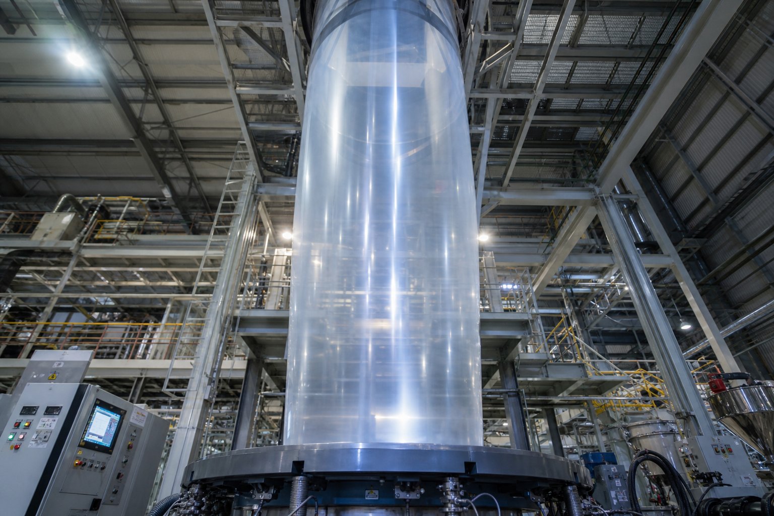
What Is Blown Film Extrusion and Why It Matters
Imagine turning a handful of tiny plastic pellets into a seamless, ultra-thin tube of film stretching dozens of meters into the air. That is exactly what happens inside a blown film extrusion line every second of every production shift. Whether you are new to polymer processing or a seasoned engineer evaluating your next capital investment, understanding this process is essential to working with flexible films.
Defining the Blown Film Extrusion Process
Blown film extrusion is a continuous manufacturing process in which thermoplastic resin — most commonly polyethylene — is melted inside an extruder, forced through an annular (ring-shaped) die, and inflated by internal air pressure into a thin-walled tube known as a bubble. As this bubble rises, an external air ring rapidly cools it until the molten polymer solidifies. The solidified tube is then collapsed into a flat layflat, pulled through nip rollers, and wound into finished rolls of tubular or slit film. The result is a versatile, seamless film used in everything from grocery bags to greenhouse covers.
What makes this form of film extrusion distinct is the biaxial stretching that occurs during bubble inflation. The melt stretches simultaneously in the machine direction (as it is pulled upward) and in the transverse direction (as air pressure expands the diameter). This dual orientation gives extruded films balanced strength — a property that flat-die methods struggle to match in a single processing step.
Why Blown Film Dominates Flexible Packaging
You might wonder why this particular technique has become the go-to method for producing flexible packaging films worldwide. The answer comes down to versatility, efficiency, and mechanical performance.
A single blown film line can produce a remarkable range of products — from thin, crystal-clear bread bags to heavy-duty construction sheeting — often by adjusting process parameters rather than swapping out major equipment. This flexibility extends across industries. In agricultural applications, blown films serve as silage wrap, mulch film, and greenhouse covers. In medical and pharmaceutical settings, they provide sterile barrier packaging. Retail, industrial shipping, and food packaging each rely on blown extrusion film for products that demand consistent quality at high volumes.
Blown film extrusion is the most common process for the production of continuous films used primarily for packaging, and it accounts for the majority of global polyethylene film output — a testament to its unmatched combination of balanced orientation, production flexibility, and cost efficiency.
The balanced mechanical properties of blown films are a direct result of the bubble inflation process. Unlike films produced on flat dies, which tend to be stronger in one direction, blown film delivers comparable tensile strength and tear resistance in both the machine and transverse directions. For end users, that translates to packaging that resists punctures during transit, agricultural covers that withstand wind stress from any angle, and stretch wraps that hold loads securely without splitting.
Economic factors reinforce the dominance as well. A blown film line typically requires a smaller footprint than a comparable cast line for the same layflat width, and it can switch between product specifications with relatively short changeover times. For converters producing multiple SKUs on tight schedules, that agility is a competitive advantage.
Yet versatility alone does not guarantee a flawless roll of film. The quality of every meter of output depends on precise control over a chain of interdependent process variables — from melt temperature and die geometry to air ring performance and haul-off speed. Each of these parameters shapes the final film's thickness, clarity, strength, and processability downstream.
How the Blown Film Extrusion Process Works Step by Step
Picture a single plastic pellet — roughly the size of a lentil — sitting in a hopper. Within minutes, it will travel through a series of tightly coordinated stages and emerge as part of a continuous, uniformly thin film winding onto a roll at the end of the line. The blown film extrusion process transforms that pellet through heat, pressure, airflow, and mechanical tension, and each stage hands off to the next with zero room for interruption. Here is exactly how it happens.
From Resin Pellets to Molten Polymer
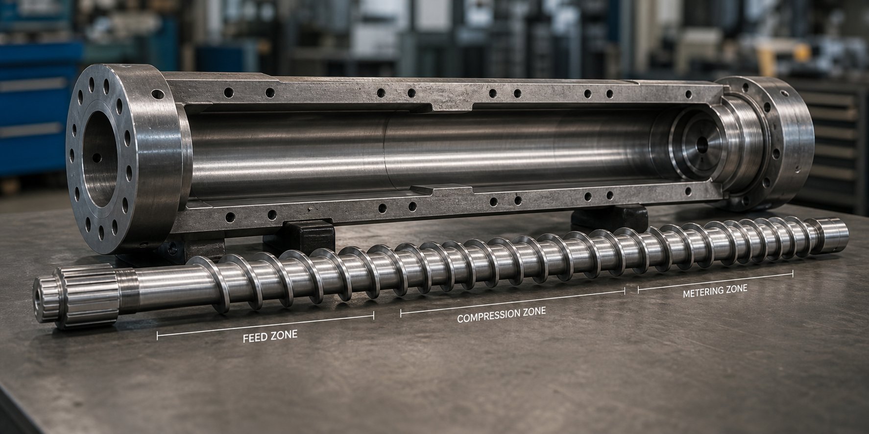
Everything begins at the feed throat, where dried resin pellets — typically polyethylene, though PP, nylon, and other thermoplastics are also common — drop by gravity from the hopper into the extruder barrel. Inside, a precision-machined screw rotates within the heated barrel, performing three jobs simultaneously: conveying the pellets forward, compressing them as channel depth decreases, and generating intense shear heat that works alongside external barrel heaters to melt the resin.
The barrel itself is divided into distinct temperature zones, each set to a specific target so the polymer transitions gradually from solid granules to a fully homogenized melt. You'll notice that screw speed plays a dual role here — it controls both throughput and melt quality. Spin the screw too fast without adequate heat input, and you get poorly melted particles; too slow, and output drops below target. By the time the molten polymer reaches the metering zone at the front of the screw, it should be a uniform, bubble-free melt ready for shaping — the foundation of reliable polymer film extrusion.
Bubble Formation and Cooling
The homogenized melt exits the extruder and enters an annular die, which distributes it into a continuous, ring-shaped curtain of molten plastic. As this thin-walled tube emerges from the die lips, a carefully regulated stream of compressed air is injected through the center of the die, inflating the tube outward like a balloon. The ratio of the inflated bubble diameter to the original die diameter — the blow-up ratio — determines the final film width and contributes to transverse-direction orientation.
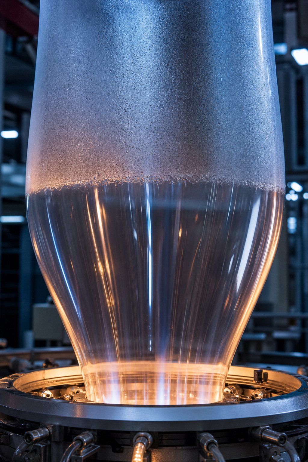
Simultaneously, an air ring mounted just above the die blasts cool air onto the outer surface of the rising bubble. This rapid cooling is critical. It locks the molecular structure in place and determines a visible landmark on the bubble called the frost line — the point where the glossy, transparent melt transitions into a hazier, semi-crystalline solid. The height of the frost line directly affects crystallinity, optical clarity, and mechanical properties. A higher frost line allows more time for molecular relaxation before solidification, while a lower frost line freezes structure quickly for improved transparency. Bubble stabilization devices, such as guide cages or iris assemblies, may surround the bubble above the frost line to dampen any sway caused by ambient air currents.
Collapsing, Hauling, and Winding
Once solidified, the bubble must be converted from a round tube into a flat sheet — a process that sounds simple but requires precise geometry. Collapsing frames, consisting of angled guide panels or roller assemblies, gently compress the bubble from both sides, folding it into a flat double-layered film called a layflat. At the top of the frame, a set of nip rollers pinch the layflat closed, sealing the air inside the bubble below and pulling the film upward at a controlled haul-off speed. This speed, relative to the extrusion rate, governs the draw-down ratio and therefore the final film gauge.
From the nip rollers, the film travels through optional in-line treatment stations — corona discharge to improve ink adhesion, or even direct printing and lamination units. Finally, it reaches the winder, where it is rolled onto cores under carefully managed tension. Too much tension stretches or distorts the film; too little produces loose, telescoping rolls that are difficult to handle downstream.
For a quick visual reference, here is the complete blown film extrusion process broken into its sequential stages:
- Resin feeding — Dried pellets enter the extruder hopper and fall into the feed throat.
- Melting and homogenization — The rotating screw and heated barrel plasticize the resin into a uniform melt.
- Die shaping — The melt is distributed through an annular die into a thin-walled tube.
- Bubble inflation — Compressed air expands the tube to the target diameter, establishing the blow-up ratio.
- Air-ring cooling — External cool air solidifies the bubble, forming the frost line.
- Bubble stabilization — Guide cages or iris devices minimize bubble sway and maintain a consistent diameter.
- Collapsing — Angled frames flatten the bubble into a double-layer layflat.
- Nip-roller haul-off — Pinch rollers seal the bubble, pull the film at a set speed, and control film thickness.
- Optional treatment — Corona discharge, printing, or lamination may occur in-line.
- Winding — The finished film is rolled onto cores under controlled tension, ready for slitting or shipment.
Each of these stages is interconnected. A change in melt temperature upstream ripples through bubble diameter, frost-line height, and final gauge downstream. That interconnection is precisely what makes the blow film extrusion process both powerful and demanding — and why experienced operators often compare it to blow film molding in its sensitivity to parameter balance. Understanding the individual steps is only the starting point; the real mastery lies in knowing how each critical parameter influences the film that comes off the winder.
Critical Process Parameters That Control Film Quality
Every stage of the blown film extrusion process feeds into the next, but the real levers that separate a flawless roll from a reject bin are a handful of interdependent process parameters. Adjust one, and the ripple travels through bubble geometry, molecular orientation, and final film performance. Here is what each variable does — and how to use it deliberately rather than reactively.
Understanding Blow-Up Ratio and Draw-Down Ratio
So, what is blow up ratio? The blow-up ratio (BUR) is the ratio of the final inflated bubble diameter to the die diameter. It is arguably the single most influential parameter in polyethylene film extrusion because it directly controls transverse-direction (TD) orientation. Increase the BUR and you stretch the melt outward more aggressively, producing a thinner film with improved TD tensile strength and better optical properties — but at the expense of machine-direction (MD) strength and stiffness. Reduce it, and the film gets thicker with stronger MD orientation. Typical BUR values range from about 2:1 to 4:1 for PE films, though some specialty applications push outside that window.
The draw-down ratio (DDR) works in the other axis. It measures how much the film is stretched in the machine direction and is calculated using the formula: DDR = die gap / (film thickness x BUR). A higher DDR increases MD tensile strength while potentially reducing TD strength — essentially the mirror image of BUR's effect. The interplay between these two ratios determines the overall orientation balance of the finished film. They can act synergistically to enhance certain properties, or they can counteract each other, which is why experienced engineers tune them in tandem rather than in isolation.
Frost Line Height, Die Gap, and Melt Temperature
Imagine watching a rising bubble shift from glossy and transparent to slightly hazy. That visible transition — the frost line — marks the point where the polymer crystallizes enough to hold its shape. Frost line height (FLH) has a direct influence on crystallinity and optical clarity. Raising the frost line gives polymer chains more time to relax before solidification, which can reduce haze by over 20% when paired with optimized cooling. Lowering it locks in orientation faster, which can improve gauge uniformity but sacrifice some clarity.
Die gap selection feeds directly into the DDR calculation. A larger die gap provides more material for stretching, allowing a higher DDR without excessive melt stress. Die gaps for PE blown film commonly fall between 1.0 mm and 2.5 mm, with the exact choice depending on target film thickness and resin viscosity.
Melt temperature varies by resin type. LDPE performs well at slightly lower temperatures to avoid thermal degradation, while LLDPE benefits from operating toward the upper end of the 190-230 degrees C range to enhance melt strength and bubble stability. HDPE demands tighter thermal control — premature crystallization at the die lip is a constant risk if temperatures drift too low. Uniform zone-to-zone profiling across the extruder barrel and die minimizes viscosity gradients that cause thickness fluctuations and melt fracture.
Line Speed and Its Impact on Film Quality
Haul-off speed — the rate at which nip rollers pull the film upward — is the final piece of the puzzle. Increase haul-off speed while keeping screw speed constant, and the film gets thinner with greater MD orientation. Decrease it, and thickness climbs while orientation drops. Sounds simple, but the catch is that any speed change also shifts the DDR, which cascades into mechanical property changes. Running too fast can introduce gauge bands and edge waviness; too slow may cause sagging or blocking on the roll. The best operators treat line speed as a fine-tuning tool, adjusting it in small increments after BUR and melt temperature are already dialed in.
The table below consolidates these critical parameters into a single reference. Bookmark it for quick access during production runs:
| Parameter | Definition | Typical Range | Effect on Film Properties |
|---|---|---|---|
| Blow-Up Ratio (BUR) | Ratio of bubble diameter to die diameter | 2:1 to 4:1 (PE films) | Higher BUR increases TD strength, improves clarity, and reduces thickness; lower BUR favors MD strength and stiffness |
| Draw-Down Ratio (DDR) | Die gap / (film thickness x BUR) | 1.5 to 3 (PE films) | Higher DDR boosts MD tensile strength and orientation; lower DDR yields thicker, less oriented film |
| Frost Line Height (FLH) | Distance from die face to solidification point | 200-800 mm (varies by resin and cooling setup) | Higher FLH improves clarity and orientation balance; lower FLH enhances gauge uniformity but may increase haze |
| Die Gap | Annular opening between inner and outer die lips | 1.0-2.5 mm (PE films) | Larger gaps support higher DDR and reduce shear stress; smaller gaps require less drawdown for thin films |
| Melt Temperature | Temperature of polymer melt at the die exit | 190-230 degrees C (polyethylenes; varies by grade) | Higher temperature improves melt homogeneity and bubble stability; excessive heat risks degradation or sagging |
| Line Speed (Haul-Off) | Speed at which nip rollers pull the film | Application-dependent | Higher speed thins film and increases MD orientation; lower speed increases thickness and reduces orientation |
What stands out in this table is how tightly each parameter links to the others. Changing the blow-up ratio without adjusting haul-off speed shifts the DDR — and therefore the entire orientation balance. Raising melt temperature without compensating at the air ring pushes the frost line higher, altering crystallinity and gauge control. This interdependence is exactly why two lines running the same resin can produce very different films: the difference lives in how these parameters are balanced against each other. And that balance becomes even more complex when different extrusion technologies — blown versus cast — enter the conversation.
Blown Film vs Cast Film Extrusion Compared
Blown and cast are two words that define the entire flexible film industry — yet many processors choose between them based on habit rather than data. Both technologies start the same way, melting resin in an extruder, but they diverge dramatically from the moment the polymer exits the die. Understanding exactly where they split — and what each method does best — helps you match the right process to your specific product requirements.
Process Differences Between Blown and Cast Film
The fundamental distinction comes down to die geometry and cooling method. In blown film extrusion, the melt flows through an annular die and is inflated vertically by internal air pressure into a thin-walled bubble. An air ring cools the outside of that bubble gradually as it rises, and the film solidifies at the frost line before being collapsed into a flat layflat. The entire process stretches the polymer in two directions simultaneously — machine direction and transverse direction — creating biaxial orientation during a single processing step.
Cast film extrusion takes a different path. The melt is pushed through a flat slot die, producing a wide curtain of molten polymer that immediately contacts a highly polished, internally cooled chill roll. This rapid quenching solidifies the film almost instantly — far faster than air cooling can accomplish — and the polymer is oriented primarily in the machine direction as it is drawn away from the die. A cast film extruder then trims the edges, and the finished web is wound onto rolls. Because a cast film extrusion machine relies on direct-contact chill rolls rather than ambient air, it achieves cooling rates that are an order of magnitude higher than a blown film line.
These opposing cooling strategies are the root cause of nearly every property difference between blown and cast films. Slow air cooling gives polymer chains time to crystallize and orient in two directions. Rapid chill-roll contact freezes chains in a more amorphous state, preserving clarity but locking in unidirectional orientation.
Film Properties and Application Trade-Offs
When you compare the two side by side, a clear pattern emerges: blown film wins on toughness and balanced strength, while cast film wins on optical quality and gauge precision.
Strength and puncture resistance. Blown film's balanced biaxial orientation gives it superior tear resistance and puncture toughness in every direction. That makes it ideal for heavy-duty bags, agricultural covers, and construction sheeting. Cast film, oriented mainly in the machine direction, tears more easily across its width — a limitation for high-stress applications.
Optical clarity and gloss. Here, cast film pulls ahead decisively. The rapid chill-roll quench suppresses crystallization, producing a film with excellent clarity and gloss. Blown film, cooled more slowly by air, develops higher crystallinity and tends to appear hazier — though modern high-output air rings have narrowed the gap significantly.
Barrier performance. Multilayer blown structures often deliver stronger barrier properties against oxygen and moisture, partly because the tighter molecular packing from biaxial orientation reduces permeability. For plastic film cast on chill rolls, barrier performance is adequate for many applications but may require additional layers or coatings to match blown film in oxygen-sensitive food packaging.
Gauge uniformity. The flat die and chill roll combination in cast extrusion provides tighter thickness tolerance across the web. Blown film can exhibit slight gauge variation around the bubble circumference, although die rotation and automatic profile control have minimized this in modern blown film lines.
Thickness range. Blown film machinery adapts more easily to thicker films — think pond liners or heavy industrial sacks. Cast lines excel at producing very thin films, sometimes reaching gauges as low as 4-5 microns with biaxial orientation downstream.
Equipment Cost and Output Considerations
Capital expenditure and throughput often drive the final decision between blown cast technologies. Cast film extrusion machines generally run at higher linear speeds, translating to greater output per hour for thin-gauge products. Their setup and changeover times also tend to be shorter, which benefits operations producing long, uninterrupted runs of a single product.
Blown film lines, however, offer a different kind of efficiency. A single line can produce a wider range of products — from thin retail bags to thick construction films — simply by adjusting BUR, haul-off speed, and die gap. That flexibility reduces the need for multiple dedicated lines. Capital costs for blown film equipment can also be lower when comparing systems that produce the same layflat width, since the annular die and vertical tower typically require a smaller floor footprint than a horizontal cast line with its chill roll stack.
Energy consumption follows a similar trade-off. Cast lines consume more energy on chill-roll cooling but less on air handling. Blown lines spend energy on blowers and air rings but avoid the massive chilled rollers. Neither method holds a universal cost advantage — the economics depend on product mix, resin type, and production volume.
The table below consolidates the comparison across the dimensions that matter most when choosing between these two technologies:
| Dimension | Blown Film Extrusion | Cast Film Extrusion |
|---|---|---|
| Die Design | Annular (ring-shaped) die | Flat slot die |
| Cooling Method | Air ring (external air cooling); optional IBC | Chilled roller (direct contact quenching) |
| Film Orientation | Biaxial (MD and TD simultaneously) | Primarily machine direction (MD) |
| Tensile Strength Balance | Balanced in MD and TD | Stronger in MD; weaker in TD |
| Optical Clarity | Moderate; higher haze due to slower cooling | Excellent clarity and gloss |
| Gauge Uniformity | Good with modern controls; slight circumferential variation possible | Very tight tolerance across web width |
| Puncture and Tear Resistance | Superior toughness in all directions | Lower, especially in the transverse direction |
| Barrier Properties | Strong, especially in multilayer structures | Moderate; may need additional layers or coatings |
| Typical Output Rate | Moderate; limited by air-cooling capacity | Higher linear speeds due to efficient chill-roll cooling |
| Equipment Cost | Generally lower for equivalent layflat width; smaller footprint | Higher chill-roll and flat-die investment; larger footprint |
| Primary Applications | Grocery bags, agricultural film, construction sheeting, heavy-duty sacks, shrink wrap | Stretch wrap, food overwrap, medical packaging, diaper backsheets, lamination films |
Neither technology is universally superior. The right choice hinges on your end-use requirements — optical clarity and high-speed output favor cast, while toughness, barrier strength, and product versatility tilt the decision toward blown film. Many large converters run both technologies side by side, routing each product to the process best suited for its performance demands. Regardless of which path you choose, the equipment that feeds the die — particularly the extruder and its screw-barrel system — remains the common foundation that both technologies share.
Essential Equipment in a Blown Film Extrusion Line
A blown film line is only as strong as its weakest component. Parameters like BUR, frost line height, and melt temperature can be dialed in perfectly on paper — yet the film still falls short if the hardware delivering and shaping the melt is not up to the task. Every piece of equipment in the line plays a specific role, and understanding how these components interact gives you the foundation to spec a new blown film extrusion machine or troubleshoot an existing one.
Before diving into individual subsystems, here is a high-level view of the major components that make up a complete blown film line:
- Extruder and screw-barrel system — melts, homogenizes, and pressurizes the resin
- Annular die — distributes the melt into a uniform tubular profile
- Air ring and internal bubble cooling (IBC) system — cools and stabilizes the bubble
- Bubble stabilizer (guide cage or iris) — dampens sway and maintains consistent diameter
- Collapsing frame — flattens the round bubble into a double-layer layflat
- Nip rollers (haul-off unit) — seals the bubble, controls film speed, and sets draw-down ratio
- Film treatment station — corona discharge, printing, or lamination (optional)
- Winder — rolls the finished film onto cores under controlled tension
- Control system — monitors temperature, pressure, gauging, and line speed in real time
Extruder Types and Screw-Barrel Systems
The single-screw extruder is the workhorse of blown film production. Imagine a precision-ground screw rotating inside a tightly toleranced barrel — together, they perform the critical job of converting solid pellets into a perfectly uniform melt. Two main feed-section designs dominate: smooth-bore and grooved-feed. Smooth-bore barrels rely on friction between the resin and barrel wall to convey pellets forward, making them forgiving with a wide range of materials. Grooved-feed barrels, by contrast, feature longitudinal or helical grooves cut into the feed zone that physically grip the pellets, dramatically increasing throughput and pressure stability — a clear advantage when running HDPE or other high-viscosity resins on a blown film extruder.
Screw geometry deserves equal attention. The length-to-diameter (L/D) ratio determines how long the resin stays under heat and shear; common values for film screws fall between 24:1 and 30:1, offering enough residence time for thorough plastication without risking thermal degradation. The compression ratio — the volume of the first feed-section groove divided by the volume of the last metering-section groove — controls how aggressively the screw compacts and melts the resin. For polyethylene film applications, compression ratios above 4:1 are common, ensuring dense, bubble-free melt delivery to the die.
The barrel itself is a wear-critical component that directly affects melt quality and output consistency. Temperature uniformity across each heating zone depends on the barrel's heat-transfer characteristics, and any wear in the bore opens up clearance between the screw flight and barrel wall, reducing pressure-building capacity and allowing melt to flow backward. For plants running PE blown film lines alongside pipe, sheet, pelletizing, or recycling operations, sourcing barrels engineered for multi-application durability matters. NANHAIYA's single screw barrel solution is a dependable option in this space — designed specifically for plastic extrusion plants that need reliable barrel support across film, pipe, sheet, pelletizing, and recycling lines, with wear-resistant materials that help maintain tight tolerances over extended production campaigns.
Die Designs for Blown Film
The annular die is where the homogenized melt gets its shape, and die geometry has a direct influence on film uniformity. Three primary designs serve the blown film market:
Spider dies use a series of metal "legs" to support an internal mandrel inside the die body. They are mechanically straightforward, but each leg interrupts the melt flow and creates weld lines in the finished film — visible weak spots with different optical characteristics. For commodity applications where minor weld-line artifacts are acceptable, spider dies remain a low-cost entry point.
Crosshead dies split the melt stream at the inlet and rejoin it on the opposite side of a cylindrical mandrel. This approach eliminates spider legs but introduces non-symmetrical flow paths — the polymer traveling to the far side of the mandrel experiences a longer residence time, which can produce thickness variation around the circumference.
Spiral mandrel dies represent the industry standard for modern blown film extruder machines. Multiple feed ports deliver melt into helical channels that wrap around the mandrel. As the channels spiral upward, their depth gradually decreases while the gap between mandrel and outer wall increases, forcing the melt to layer and blend into a seamless, weld-line-free tube. The result is excellent thickness uniformity and consistent optical properties — exactly what high-quality packaging demands.
Air Rings, Collapsing Frames, and Winding Systems
Cooling hardware determines how fast you can run the line and how consistent the film will be. A single-lip air ring directs a single stream of cool air upward along the bubble surface. It is simple, reliable, and adequate for many general-purpose films. A dual-lip air ring adds a second, independently adjustable air stream that provides more aggressive cooling and finer control over frost line height — essential for high-output blown film machines processing LLDPE or metallocene resins at elevated speeds.
For even greater throughput, many modern lines incorporate Internal Bubble Cooling (IBC). This system circulates cool air inside the bubble through a supply and exhaust passage in the die, removing heat from both surfaces simultaneously. IBC automates width control and bubble stability, leading to improved thickness uniformity, reduced material waste, and higher production rates — a meaningful upgrade for any blown film extrusion machine targeting premium output.
Downstream of the air ring, collapsing frames use angled panels or low-friction roller assemblies to transition the round bubble into a flat layflat. Proper alignment is non-negotiable; even a slight skew creates wrinkles that persist all the way to the finished roll. Nip rollers at the top of the tower seal the bubble and set the haul-off speed, and many lines add oscillating or rotating haul-off units to distribute any minor gauge variation evenly across the roll width.
The final station — the winder — seems deceptively simple, but tension control here determines whether the roll ships flat and uniform or arrives at the converter with telescoping edges and blocking. Surface winders maintain contact pressure against the roll face, while center winders drive the core directly. Gap winding, which maintains a precise air gap between the lay-on roller and the roll surface, offers the tightest tension control for thin, stretch-sensitive films.
Every component in this equipment chain feeds the next. A worn barrel undermines melt consistency, which the best spiral die in the world cannot fully correct. A perfectly extruded melt means nothing if the air ring cannot cool it uniformly, and flawless cooling is wasted if the collapsing frame introduces wrinkles. That interdependence extends beyond the hardware itself — it reaches into the film's layer structure, where monolayer simplicity and multilayer complexity each place very different demands on the equipment that supports them.
Monolayer vs Multilayer Co-Extrusion Blown Film
A single extruder feeding a single die produces a single-layer film — straightforward, reliable, and perfectly adequate for a wide range of everyday products. But what happens when that one layer cannot deliver the barrier protection, sealability, or strength your application demands? That is where multilayer co-extrusion enters the picture, stacking two, five, or even nine distinct polymer layers into a single extruded film structure. The choice between monolayer and multilayer is not about which is "better" — it is about matching film architecture to end-use performance requirements.
When Monolayer Film Is Sufficient
For general-purpose applications where barrier properties are not critical, a monolayer blown polyethylene film handles the job efficiently and economically. Think trash bags, garment covers, shipping envelopes, construction sheeting, and agricultural mulch film. These products rely on mechanical strength, flexibility, and consistent gauge — properties that a single layer of LDPE, LLDPE, or HDPE delivers without difficulty.
The appeal is simplicity. A monolayer blown film line requires just one extruder, fewer process variables, and less operator expertise to produce consistent results. Changeovers between products are faster, maintenance costs stay lower, and the resin formulation process is uncomplicated. For manufacturers producing commodity pe blown film extrusion products at competitive margins, monolayer remains the workhorse configuration.
Multilayer Co-Extrusion Configurations
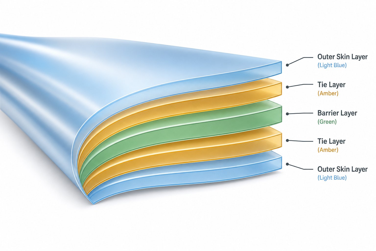
Imagine building a sandwich where every layer serves a specific purpose — one for sealing, one for strength, one to block oxygen, and adhesive layers to hold incompatible materials together. That is exactly how multilayer co-extrusion works. Multiple extruders feed different polymers into a single co-extrusion die, producing a composite film in one continuous pass.
Each layer type plays a defined role:
- Skin layers (outer/inner) — provide sealability, printability, and surface finish
- Core layers — contribute mechanical strength and stiffness
- Barrier layers — materials like EVOH or nylon (PA) block oxygen, moisture, or aroma transmission
- Tie layers — adhesive resins that bond chemically incompatible polymers together, preventing delamination
A classic example is the 5-layer structure PE/tie/EVOH/tie/PE, widely used for oxygen-sensitive food products like processed meats and cheeses. The outer PE layers handle sealing and printability, the EVOH core provides an oxygen barrier up to ten times more effective than PE alone, and the tie layers ensure the structure stays bonded during processing and throughout shelf life.
Polyethylene blown film extrusion in 3-layer configurations — typically A/B/A or A/B/C — covers a broad middle ground. The outer layers use virgin resin for appearance and performance, while the core can incorporate recycled or lower-cost materials to reduce overall resin expense. This approach is popular for consumer packaging, stretch films, and lamination base films where moderate barrier enhancement is sufficient.
Moving up to 7-layer and 9-layer systems unlocks highly specialized extrusion film structures for demanding end uses. These configurations allow converters to place ultra-thin barrier layers precisely within the structure, combine multiple barrier materials for synergistic protection, and incorporate functional additives — such as UV stabilizers or antistatic agents — in targeted layers without compromising the rest of the film. Pharmaceutical blown film packaging, for instance, often relies on these advanced structures to maintain drug stability against moisture and oxygen ingress over extended storage periods.
Choosing the Right Layer Count
More layers unlock better performance — but they also bring greater equipment complexity, tighter process control demands, and higher capital investment. Every additional extruder adds a melt stream that must be precisely temperature-controlled, pressure-matched, and volumetrically balanced at the die. The question is whether your application truly requires that level of engineering.
The table below maps common configurations against their typical applications, barrier capability, equipment complexity, and relative cost to help you find the right fit:
| Configuration | Typical Applications | Barrier Capability | Equipment Complexity | Relative Cost |
|---|---|---|---|---|
| Monolayer (1 layer) | Trash bags, garment bags, agricultural mulch, construction sheeting | Low — single resin properties only | Low — one extruder, simple controls | Lowest |
| 3-Layer (A/B/A or A/B/C) | Shopping bags, industrial packaging, lamination films, stretch wrap | Moderate — core layer can add recycled content or mild barrier | Moderate — two or three extruders | Moderate |
| 5-Layer | Food packaging (meat, cheese, snacks), vacuum bags, medical packaging | High — dedicated EVOH or PA barrier layer with tie layers | High — five extruders, precise layer ratio control | High |
| 7-Layer and above | High-barrier food, pharmaceutical packaging, specialty industrial films | Very high — multiple barrier materials, ultra-thin functional layers | Very high — advanced die design, gravimetric dosing, automated gauging | Highest |
A practical rule of thumb: start with the simplest structure that meets your performance spec, then add layers only when testing confirms a measurable benefit. A 3-layer line offers significant versatility for producers stepping beyond monolayer, while a 5-layer system hits the sweet spot for most food and medical packaging. Investing in 7-layer or 9-layer capacity makes strategic sense when your product portfolio demands multiple barrier materials or when you plan to expand into high-barrier segments over time.
Regardless of how many layers you choose, every configuration is only as reliable as the process control behind it. Layer ratios must stay consistent, melt temperatures must remain stable, and any deviation — a gel, a temperature spike, a thickness drift — shows up in the finished roll as a defect. Knowing how to diagnose and correct those defects quickly is what separates productive shifts from costly downtime.
Troubleshooting Common Blown Film Defects
Even a well-tuned blown film line will eventually throw a curveball. A subtle gauge band appears across the roll, gels dot an otherwise perfect web, or the bubble starts swaying unpredictably during a night shift. The difference between a minor hiccup and hours of lost production often comes down to how quickly operators identify the root cause — and whether they chase the right corrective action first. This troubleshooting guide covers the defects most frequently encountered in blown film manufacturing and maps each one to its likely causes and fixes.
Gauge Variation and Bubble Instability
Uneven film thickness is one of the most costly defects on any blown film line. When gauge variation is significant, operators are forced to target a thicker average just to keep the thinnest spots above specification — a practice known as resin giveaway that silently erodes margins on every roll produced.
What causes it? The usual suspects include contamination or damage at the die lips, uneven airflow distribution around the air ring, temperature inconsistencies across barrel or die zones, and worn screw or barrel components that allow melt to channel unevenly. On older blown film extruders with multi-inlet air ring designs, pressure differences between hose connections can introduce circumferential cooling imbalances that show up directly as thickness bands in the finished film.
Bubble instability is closely related. You might see the bubble "breathing" — rhythmically expanding and contracting — or dancing side to side, or spiraling in a helical pattern. Each symptom points to a different imbalance. Breathing usually signals inconsistent internal air pressure or fluctuating extruder output. Dancing often traces back to uneven air ring flow or ambient drafts near the tower. Helical instability frequently indicates a melt temperature gradient around the die circumference. As instability increases, operators are forced to reduce output to maintain a stable process — which means throughput drops even though the extruder has capacity to spare.
Corrective actions start with the simplest checks: clean the die lips, verify that all air ring hoses are unobstructed and equal in length, and confirm that barrel and die temperature zones are reading within target. If the problem persists, inspect the screw and barrel for wear and evaluate whether an IBC system or modern single-inlet air ring could improve bubble stability at higher output rates.
Surface Defects and Optical Issues
Surface quality complaints typically fall into four categories, each with a distinct signature:
Gels appear as small bumps or specks embedded in the film. They can originate from unmelted resin particles (indicating insufficient screw L/D or low barrel temperatures), crosslinked polymer fragments (from degraded material stuck in dead spots within the die or adapter), or foreign contamination in the resin stream. Reducing barrel temperatures in overheated zones, purging the system, and inspecting screen packs are the first lines of defense. Persistent gel issues may require disassembling the die for a thorough cleaning.
Melt fracture — often called sharkskin — gives the film surface a rough, ridged texture. It occurs when shear stress at the die lip exceeds a critical threshold. The fix typically involves raising the melt temperature or widening the die gap to reduce shear rate, or applying a processing aid that lubricates the die surface.
Die lines are thin, continuous streaks running in the machine direction, caused by scratches, buildup, or damage on the die land surface. Cleaning or polishing the die lips usually resolves them, but recurring die lines may signal the need for die reconditioning.
Poor optical clarity — haze, low gloss, or a milky appearance — links directly to cooling conditions. Blown film machines that cool the bubble too slowly allow excessive crystallization, which scatters light and increases haze. Increasing air ring velocity, lowering the frost line, or upgrading to a dual-lip air ring can sharpen clarity significantly. If milky patches appear in localized areas, suspect contamination by an incompatible polymer rather than a cooling issue.
Wrinkles, Blocking, and Other Winding Defects
Defects that appear at the winder are especially frustrating because the film itself may be perfectly extruded — the problem originates downstream.
Wrinkles before the nip roll typically point to a misaligned collapsing frame, uneven tension across the web, or a non-uniform extrusion process upstream of the nip. Checking frame alignment, verifying that guide rollers spin freely, and confirming even gauge distribution around the bubble are essential first steps.
Film blocking — layers sticking together inside the wound roll — is a defect that often does not reveal itself until the converter tries to unwind. Causes include excessive winding tension or nip pressure, insufficient slip or antiblock additives in the resin formulation, corona treatment levels set too high, or elevated film temperature at the winder. According to web handling specialists, blocking is linear to interlayer pressure — which peaks near the core and increases with roll length. Winding softer rolls by reducing tension and nip load, cooling the film before winding, and running shorter rolls are all proven countermeasures.
The troubleshooting table below consolidates the most common defects encountered on blown film lines into a scannable reference. Keep it handy during production — matching the symptom to the right corrective action can save hours of trial and error on a film blowing extruder machine.
| Defect | Likely Causes | Corrective Actions |
|---|---|---|
| Gauge variation (thickness bands) | Die lip contamination or damage; uneven air ring flow; barrel/die temperature inconsistency; worn screw or barrel | Clean and inspect die lips; equalize air ring hoses; verify zone temperatures; check screw-barrel wear and replace if needed |
| Bubble instability (breathing, dancing, helical) | Inconsistent internal air pressure; uneven air ring flow; ambient drafts; melt temperature gradient around die | Stabilize IBC pressure; inspect air ring for obstructions; shield tower from drafts; check die heater band uniformity |
| Gels (unmelts, crosslinked particles) | Insufficient melt temperature; degraded polymer in dead spots; contaminated resin; worn screen packs | Raise barrel temperatures in feed/transition zones; purge system thoroughly; inspect and clean die; replace screens |
| Melt fracture (sharkskin) | Excessive shear stress at die lip; melt temperature too low; die gap too narrow | Increase melt temperature; widen die gap; add polymer processing aid to reduce die-lip friction |
| Die lines | Scratched or contaminated die land; buildup at die exit | Clean or polish die lips; recondition die land if scratches are deep; purge with cleaning compound |
| Poor optical clarity (haze, low gloss) | Slow cooling; high frost line; excessive crystallization; contamination by incompatible polymer | Increase air ring velocity; lower frost line height; upgrade to dual-lip air ring; verify resin purity |
| Wrinkles (pre-nip or in roll) | Misaligned collapsing frame; uneven web tension; gauge variation; roller drag | Realign collapsing frame panels; check roller bearings; improve gauge uniformity at the die |
| Film blocking (layers stick in roll) | Excessive winding tension or nip pressure; insufficient slip/antiblock additives; high film temperature at winder; excessive corona treatment | Reduce winding tension and nip load; add or increase antiblock/slip additives; cool film before winding; lower corona treatment level; consider shorter rolls |
| Discoloration (yellowing, browning) | Melt temperature too high; excessive residence time; resin degradation | Reduce barrel or die temperatures; check for flow restrictions causing long residence time; purge and restart |
A pattern runs through nearly every row in that table: most defects trace back to either thermal control, mechanical wear, or airflow uniformity — the same three pillars that determine output quality on any blown film extrusion line. Fixing today's defects solves an immediate production problem, but the broader industry is already working on solutions that prevent many of these issues from arising in the first place. Advances in automation, sustainability-driven material shifts, and next-generation line designs are reshaping what blown film operations will look like in the years ahead.

Innovations and Sustainability Trends in Blown Film Technology
Preventing defects is one thing — rethinking the entire film manufacturing model is another. The blown film industry is evolving on two parallel fronts: sustainability-driven material innovation and automation technologies that make high-performance production accessible even to operators with limited experience. Together, these shifts are redefining what a modern plastic film extrusion operation looks like.
Sustainability and Circular Economy in Blown Film
Brand owners and regulators are pushing converters toward circular packaging at an accelerating pace. Post-consumer recycled (PCR) resins are appearing in an increasing number of industrial blown film structures, from stretch wraps to secondary packaging. The challenge? PCR feedstocks often contain contaminants, show variable melt flow indices, and behave differently under shear compared to virgin grades. Extruder screw-barrel systems must tolerate those inconsistencies without sacrificing gauge uniformity or throughput.
Mono-material multilayer designs are gaining ground as a direct response to recyclability concerns. Instead of combining PE with PET or nylon — structures that contaminate single-stream recycling — converters are building all-PE multilayer films where each layer uses a different PE grade tailored for stiffness, sealing, or barrier performance. The Association of Plastic Recyclers (APR) has expanded its Design for Recyclability Recognition Program to include mono-material PE film substrates, giving converters third-party validation that their structures are compatible with North American recycling infrastructure. Bio-based and compostable film alternatives are also emerging, though they remain niche due to processing limitations and higher resin costs.
High-Speed Lines, MDO, and Automation
Machine direction orientation (MDO) is arguably the most transformative blown film technology of the past decade. An MDO unit, positioned inline after the bubble is collapsed, heats and stretches the film in the longitudinal direction at ratios around 5:1. The result is a thinner, stiffer, optically superior film that can replace multimaterial PE/PET laminates with recyclable all-PE structures — a features of high output thin film blowing machine setups that brand owners increasingly demand. Processors have already produced MDO-PE films as thin as 18 micrometers on continuous production runs exceeding 72 hours, narrowing the cost gap with the PET films they replace.
Automation and AI integration are advancing just as rapidly. At K 2025, major film blowing machine builders unveiled systems designed to minimize human intervention across the entire production cycle:
- AI-driven output optimization — systems like W&H's Easy2Run analyze machine component reserves and automatically maximize throughput at the push of a button, addressing the reality that most blown film lines run at only 50-65% of capacity
- AI-powered operator assistants — Reifenhauser's NEXT ecosystem provides a chatbot that delivers real-time troubleshooting recommendations, even for inexperienced operators, by drawing on decades of accumulated process knowledge
- Automated startup and changeover — digital startup assistants store recipe parameters and walk operators through system startup in as few as four automated steps
- Bubble contour detection — permanently installed cameras photograph the bubble every 0.5 seconds, identify optimal geometry, and enable automatic reproduction of saved contours during product changeovers
- Real-time gauging and predictive maintenance — in-line sensors feed data into dashboards for automated OEE calculations and data-driven decision-making
- Next-generation MDO hardware — patented mini nip roller systems reduce neck-in by up to 50%, while vacuum stretching rollers improve roll conformity and flatness
- High-output die and cooling upgrades — new die head and triple-lip air ring combinations deliver throughput increases of up to 30% over previous generations
The common thread across all of these innovations is reducing dependence on operator expertise while simultaneously raising output quality and speed. For film manufacturing operations struggling with workforce turnover, these technologies do not just improve efficiency — they protect institutional knowledge by embedding it directly into the control system.
Sustainability and automation are converging, too. Processing recycled resins reliably at high speeds demands exactly the kind of real-time process adjustment that AI-driven controls excel at. And MDO's ability to downgauge films while maintaining performance directly reduces material consumption per package — a measurable sustainability win that also improves unit economics. The question for most converters is no longer whether to adopt these technologies, but which components and partners to invest in first.
Choosing the Right Components for Your Blown Film Line
Sustainability roadmaps and AI-driven controls can reshape your production strategy — but none of it matters if the core hardware feeding your die is poorly specified. Every innovation discussed so far depends on one constant: a reliable, well-matched set of mechanical components turning resin into consistent melt, shift after shift. Whether you are building a new blown film extrusion line from scratch or upgrading an aging system to handle recycled content and thinner gauges, the component selection process follows the same logic.
Matching Components to Your Production Goals
Before requesting quotes for any piece of blown film machinery, take a step back and define four foundational variables that will drive every specification downstream:
- Resin types — Are you running straight LDPE, blending LLDPE with metallocene grades, processing HDPE at high blow-up ratios, or incorporating PCR content? Each resin family demands different screw geometries, compression ratios, and barrel wear characteristics.
- Target film thickness range — A line optimized for 15-micron retail bags faces very different cooling and tension demands than one producing 200-micron construction sheeting. Your thickness window determines die gap selection, air ring capacity, and haul-off system sizing.
- Output requirements — Translate your daily or monthly production target into a realistic saleable kg/h figure. As capacity planning experts emphasize, always account for real-world losses — edge trim, startup waste, changeover downtime — rather than relying on nameplate throughput alone.
- End-use applications — Food-contact packaging, agricultural mulch, and industrial stretch wrap each impose distinct performance and regulatory requirements that ripple back into layer count, material selection, and equipment configuration.
Among all the components in a film extruder, the screw-barrel system stands out as the heart of the operation. Its design and material quality directly determine melt homogeneity, energy efficiency, and maintenance intervals. A worn barrel allows melt to leak backward past the screw flights, reducing output pressure and introducing temperature inconsistencies that no amount of downstream tuning can correct. Industry data suggests that roughly a quarter of extrusion failures trace back to premature barrel wear — a statistic that underscores why barrel selection deserves as much engineering attention as the die or air ring.
Screw geometry must match your primary resin. A compression ratio around 3.5:1 works well for standard LDPE and LLDPE blown film, but switching to biodegradable blends or high-filler recycled content may call for a gentler 2.5:1 to 3.0:1 ratio to avoid thermal degradation and bubble instability. The L/D ratio, barrel metallurgy, and feed-section design all need to align with the specific materials and output targets you defined above.
Building a Reliable Blown Film Operation
Sourcing components from manufacturers who specialize in extrusion-grade barrels and screws — and who offer application support across different line configurations — is one of the most practical steps you can take to protect your investment. A blow film extruder is only as consistent as the barrel feeding it, and generic replacement parts rarely deliver the tolerances that high-quality film production demands.
NANHAIYA's single screw barrel solution is a strong contender for plants seeking reliable barrel performance across multiple extrusion applications. Designed for plastic extrusion operations running blown film, pipe, sheet, pelletizing, and recycling lines, their barrels are engineered with the wear-resistant materials and dimensional precision that PE film extrusion demands. That breadth of application coverage is worth noting — a supplier who understands the demands of recycling lines, pipe extrusion, and film production simultaneously brings cross-application engineering insight that single-focus vendors often lack.
When evaluating any screw-barrel supplier for your film extrusion machine, run through this checklist to ensure you are comparing options on the dimensions that actually affect production uptime and film quality:
- Material compatibility — Does the supplier offer barrel metallurgies matched to your resin types, including bimetallic options for abrasive or filled materials?
- Wear resistance — What hardness ratings, surface treatments, and alloy compositions are available? Barrels that maintain tight bore tolerances over extended campaigns reduce scrap and energy consumption.
- Lead time — How quickly can the supplier deliver standard and custom barrel sizes? Unplanned downtime waiting for a replacement barrel is one of the most expensive losses in any blown film operation.
- Application engineering support — Can the supplier recommend screw-barrel configurations for your specific resin, output target, and film thickness range? Technical consultation at the specification stage prevents costly mismatches after installation.
- Range of extrusion applications covered — Suppliers serving film, pipe, sheet, pelletizing, and recycling operations accumulate broader process knowledge than those focused on a single niche, which translates into more versatile product designs and faster problem-solving.
A blown film extrusion line is a system, not a collection of parts. The best die in the world cannot compensate for a barrel that delivers inconsistent melt, and the most advanced AI control system cannot override the physics of a worn screw. By starting your specification process with clear production goals, prioritizing the screw-barrel system as the foundation of melt quality, and partnering with component suppliers who offer both engineering depth and application breadth, you set the stage for a line that delivers flawless rolls — not just on commissioning day, but thousands of production hours later.
Frequently Asked Questions About Blown Film Extrusion
1. What is blow up ratio in blown film extrusion?
Blow-up ratio (BUR) is the ratio of the inflated bubble diameter to the die diameter. It controls transverse-direction orientation and film width. For polyethylene films, typical BUR values range from 2:1 to 4:1. A higher BUR stretches the melt outward more aggressively, producing thinner film with improved transverse-direction tensile strength and better optical properties, while a lower BUR yields thicker film with stronger machine-direction orientation. BUR works in tandem with the draw-down ratio (DDR), so engineers typically tune both parameters together to achieve the desired balance of strength, clarity, and gauge.
2. What is the difference between blown film and cast film extrusion?
Blown film extrusion uses an annular die and air inflation to create a vertical bubble that cools gradually via an air ring, producing biaxially oriented film with balanced strength in both machine and transverse directions. Cast film extrusion pushes melt through a flat slot die onto a chilled roller, cooling the film almost instantly and orienting it primarily in the machine direction. Blown film offers superior toughness and puncture resistance, while cast film delivers better optical clarity and tighter gauge uniformity. Equipment costs, output rates, and product flexibility also differ — blown film lines have smaller footprints and greater product versatility, whereas cast lines typically achieve higher linear speeds for thin-gauge products.
3. What are the most common defects in blown film manufacturing?
The most frequently encountered defects include gauge variation (uneven thickness caused by die lip contamination, uneven air ring flow, or worn screw-barrel components), bubble instability (breathing, dancing, or helical movement linked to air pressure fluctuations or melt temperature gradients), gels (unmelted particles or crosslinked fragments), melt fracture or sharkskin (rough surface from excessive shear stress at the die lip), die lines (streaks from damaged die land surfaces), poor optical clarity (haze from slow cooling), wrinkles (from misaligned collapsing frames), and film blocking (layers sticking together due to excessive winding tension or insufficient slip additives). Most defects trace back to thermal control, mechanical wear, or airflow uniformity issues.
4. How does multilayer co-extrusion improve blown film performance?
Multilayer co-extrusion stacks two or more distinct polymer layers into a single film structure during one continuous pass. Each layer serves a specific function — skin layers provide sealability and printability, core layers add mechanical strength, barrier layers such as EVOH or nylon block oxygen or moisture transmission, and tie layers bond incompatible polymers together. A common 5-layer PE/tie/EVOH/tie/PE structure, for example, delivers oxygen barrier performance up to ten times better than PE alone. Configurations range from 3-layer setups for moderate enhancement to 7-layer or 9-layer systems for pharmaceutical and high-barrier food packaging, though added layers increase equipment complexity and capital cost.
5. Why is the screw-barrel system so important in blown film extrusion?
The screw-barrel system is the heart of any blown film line because it converts solid resin pellets into a homogeneous, pressurized melt. Screw geometry — including L/D ratio, compression ratio, and metering zone design — controls melt quality, throughput, and energy efficiency. The barrel's bore tolerance and heat-transfer characteristics directly affect temperature uniformity across heating zones. Any wear in the barrel opens clearance between the screw flights and barrel wall, reducing output pressure and causing melt channeling that leads to thickness variations in the finished film. Suppliers like NANHAIYA (nhyscrew.com) offer single screw barrel solutions engineered for multi-application durability across film, pipe, sheet, pelletizing, and recycling lines.
Written by
Nanhaiya Technical Team
Zhoushan Nanhaiya Plastic Machinery Co., Ltd.
The Nanhaiya technical team supports screw and barrel manufacturing projects through application review, technical communication, custom manufacturing coordination, and production and quality control.
Discuss Your Application
Related Articles
More insights on screw barrel technology and plastics processing.

What Nobody Tells You About Screw Barrel For Plastic Machine Design
Oct 10, 2026
Learn how screw barrel for plastic machine design affects melt quality, throughput, and wear life. Covers geometry, resin matching, troubleshooting, and sourcing.
Read Article
Single Screw Extruder for Sheet: Stop Guessing, Start Specifying
Oct 9, 2026
Learn how to specify a single screw extruder for sheet production. Covers screw geometry, resin-specific processing, troubleshooting, and maintenance best practices.
Read Article
PE Pipe Extruder Machine: What Datasheets Won't Tell You
Oct 9, 2026
Learn how a PE pipe extruder machine works, key specs explained, material grade selection, maintenance tips, and buyer guidance beyond the datasheet.
Read ArticleLooking for something else?
Search by material, symptom or product and jump straight to the relevant page.
These are navigation suggestions based on keyword matching — not a quotation, not a delivery commitment, and not a substitute for engineering review. Final specification is confirmed by our engineers against your drawings and processed material.
Need help with screw barrel selection?
Share your machine model, processed material and application. Our team can help with pricing and technical support.