


What Is a Plastic Sheet Extrusion Line and Why It Matters
Imagine a single production mistake - a slightly worn screw, an overlooked temperature drift - quietly eating into your profit margins for weeks before anyone notices. That scenario plays out in sheet extrusion facilities every day. Before you can prevent those hidden losses, you need a rock-solid understanding of the system itself.
Defining the Plastic Sheet Extrusion Line
A plastic sheet extrusion line is an integrated production system that melts thermoplastic resin and continuously forms it into flat sheet of controlled thickness and width, using a sequence of feeding, melting, die-forming, cooling, and cutting stations working in unison.
Every station in this sheetline is interdependent. A feeding inconsistency upstream ripples into gauge variation downstream. A die lip misadjustment shows up as scrap at the stacker. That interconnected nature is exactly what makes these lines both powerful and unforgiving.
Why Sheet Extrusion Matters Across Industries
Sheet extrusion ranks among the highest-volume segments in plastics manufacturing, and the numbers reflect it. The global extrusion sheet market was valued at roughly 23.36 billion USD in 2024 and is projected to reach 42.72 billion USD by 2035, growing at a 5.64% CAGR. Packaging, automotive interiors, construction panels, and medical trays all depend on continuous flat-sheet output. Whether you are running used extruders refurbished for commodity packaging or a brand-new chemical-resistant extrusion machine processing rigid PVC for industrial lining, the core production logic remains the same.
Overview of the Production Workflow
At a high level, the workflow follows a straight path: raw resin is dried and fed into the extruder barrel, where a rotating screw melts and pressurizes it. The molten polymer passes through a screen changer for filtration, then enters a flat die that spreads the melt across the full sheet width. A polishing or chill-roll stack cools and finishes the surface, while thickness gauging confirms dimensional accuracy. Finally, edge-trim reclaimers, haul-off units, and winders or sheeters convert the continuous web into finished product.
Simple in concept - yet each of those stations hides specification choices and operating variables that directly control quality, throughput, and cost per kilogram. The sections ahead break down every component, every polymer-specific configuration, and every defect pattern you need to master.
Every Component in a Polymer Sheet Extrusion Line Explained
A plastic sheet extrusion line is only as strong as its weakest station. Skip one component or under-specify it, and the bottleneck will surface as scrap, gauge drift, or lost hours. Below is a production-flow walkthrough of all nine stations - the same sequence the polymer itself follows from pellet to finished sheet.
Raw Material Handling and Feeding Systems
Everything starts before the resin ever touches the extruder. Vacuum loaders transport pellets from storage silos or gaylords into the system, keeping the feed path sealed against contamination. For hygroscopic polymers like PET or nylon, desiccant dryers pull residual moisture down to safe levels - typically below 50 ppm - because even small traces of water create bubbles and surface defects once the melt hits the die.
Gravimetric blenders sit directly above the feed throat, dosing virgin resin, regrind, color concentrate, and additives by weight rather than volume. Why does that matter? Volume-based feeding shifts every time bulk density changes - a different pellet shape, a new regrind ratio, or temperature swings in the warehouse. Gravimetric control removes that variable, delivering a consistent recipe shot after shot. Think of this station as the line's ingredient scale: if the recipe is wrong here, no amount of downstream tuning can fix it.
The Extruder and Melt Delivery System
The extruder is the heart of sheet extrusion. A rotating screw inside a heated barrel conveys, compresses, and melts the polymer through distinct feed, transition, and metering zones. The drive motor and gearbox supply the torque, while multiple barrel heater bands maintain a precise temperature profile from feed throat to discharge.
Directly after the barrel, two components guard melt quality. The screen changer holds replaceable mesh packs that trap gels, degraded particles, and foreign contaminants before they reach the die. A gear-type melt pump, mounted between the screen changer and the die, isolates pressure fluctuations generated by screw rotation and delivers rock-steady volumetric flow. This separation of duties is critical: the extruder melts and mixes, the screen changer cleans, and the melt pump meters - each station owning one job and doing it well.
Downstream Equipment From Die to Finished Sheet
Once metered melt exits the pump, the flat die - often a coat-hanger design - spreads it evenly across the full web width. The molten curtain drops onto a polishing or chill-roll stack, where chrome-finished rolls simultaneously cool the sheet and impart surface quality. Roll temperature, gap setting, and nip pressure at this station directly control gloss, flatness, and residual stress.
From the roll stack, the sheet passes through a thickness gauging station. Beta-ray, X-ray, or capacitance scanners sweep the cross-web profile continuously, feeding data back to die-bolt actuators for real-time correction. Edge-trim knives then remove uneven borders, and a reclaim system grinds those trimmings for reintroduction at the blender - recovering material that would otherwise be waste. The haul-off unit pulls the sheet at a controlled speed, maintaining consistent tension without stretching or distorting the web. Finally, a winder rolls thin-gauge sheet onto cores, while thicker sheet routes to a sheeter or stacker that cuts and stacks flat panels to length.
Skipping or cheapening any single station creates a cascade. A missing melt pump means pressure surges travel straight into the die. A poorly calibrated haul-off introduces periodic thickness bands. An absent reclaim system turns edge trim into pure scrap cost. The table below maps every component to its role, specification priority, and position in line.
| Component | Primary Function | Key Specification to Watch | Typical Position in Line |
|---|---|---|---|
| Vacuum Loader & Dryer | Conveys and conditions raw resin to target moisture level | Drying temperature and dewpoint; throughput capacity (kg/h) | 1 - Material handling |
| Gravimetric Blender | Doses virgin, regrind, and additives by weight | Dosing accuracy (±0.5% or better); number of ingredient stations | 2 - Feed throat |
| Extruder (Barrel, Screw, Drive, Heaters) | Melts, mixes, and pressurizes polymer | Screw L/D ratio; barrel diameter; motor power (kW); zone count | 3 - Core melt unit |
| Screen Changer | Filters contaminants from the melt stream | Screen mesh size; change type (manual, continuous, backflush) | 4 - Post-extruder |
| Melt Pump (Gear Pump) | Meters melt flow and stabilizes pressure to the die | Volumetric capacity (cc/rev); max pressure rating (bar) | 5 - Pre-die |
| Flat / T-Die | Distributes melt uniformly across the sheet width | Die width; lip-gap range; internal channel design | 6 - Sheet forming |
| Polishing / Chill-Roll Stack | Cools sheet and sets surface finish and flatness | Roll diameter; temperature control range; surface finish (Ra) | 7 - Cooling and calibration |
| Thickness Gauging Station | Measures cross-web thickness profile in real time | Sensor type (beta, X-ray, capacitance); scan speed; resolution | 8 - Quality measurement |
| Edge-Trim and Reclaim System | Removes uneven edges and grinds trim for reuse | Trim knife positioning accuracy; grinder throughput (kg/h) | 9 - Waste recovery |
| Haul-Off Unit | Pulls sheet at controlled speed to maintain tension | Speed range (m/min); nip pressure adjustment; drive type | 10 - Web transport |
| Winder / Sheeter / Stacker | Converts continuous web into rolls, cut sheets, or stacked panels | Max roll diameter or cut length; tension control; changeover time | 11 - End of line |
Each row in that table represents a potential failure point - and a potential margin leak. Yet among all these stations, one component exerts more influence over sheet uniformity than any other: the die. Its internal geometry determines whether your melt spreads evenly or pools toward the center, and that topic deserves a section of its own.

Die Design Principles That Control Sheet Quality
The die is the one component in your extrusion line that touches every square millimeter of finished sheet. A poorly designed or improperly adjusted die turns even the best-melted polymer into off-spec material - thick in the center, thin at the edges, or streaked with flow lines. Understanding what happens inside that steel block is the difference between consistent production and constant rework.
Coat-Hanger Die Geometry and Flow Distribution
Picture an ordinary wire coat hanger: a central hook feeds into two arms that spread outward and then curve back. A coat-hanger die mirrors that shape internally. Molten polymer enters through a central inlet and flows into a tapered manifold channel that fans outward toward both edges. The manifold progressively narrows in cross-section as it moves from center to edge, which balances the pressure drop so polymer arrives at the die lip at a uniform velocity across the full width.
This geometry is anything but arbitrary. Research on coat-hanger die optimization shows that the manifold profile, whether circular or rectangular in cross-section, must be precisely calculated based on the polymer's rheological behavior to achieve uniform outlet velocity. Even small design errors amplify across wide dies, creating thickness bands that no amount of downstream adjustment can fully correct. Internal manifold surfaces are typically polished to a mirror finish and chrome-plated, reducing drag that could create dead spots where polymer degrades and eventually breaks free as gels or discolored specks.
By contrast, a simpler T-slot die uses a straight channel without the tapered manifold geometry. It costs less and works adequately for narrow widths or less demanding applications - think prototyping runs or low-volume commodity sheet. However, for any serious extrusion production line running widths beyond 1,000 mm, the coat-hanger design's superior flow distribution makes it the standard choice in the sheet extruder machine market.
Restrictor Bar and Lip Gap Adjustment Methods
Even a perfectly designed manifold cannot account for every real-world variable - batch-to-batch resin differences, ambient temperature shifts, or slight screw-wear changes in melt pressure. That is where operator-adjustable controls come in.
The restrictor bar (sometimes called a choker bar) sits inside the die body between the manifold and the lip. By adjusting individual bolts along its length, operators alter the flow channel height at specific cross-web positions, throttling polymer flow in zones that run too thick and opening zones that run too thin. Think of it as a coarse-adjustment tool for situations where lip-bolt correction alone cannot achieve a stable production state - especially with high-output lines or formulations containing a high proportion of regrind.
At the die lip itself, two design philosophies exist. A flexible-lip die relies on the elasticity of the lip steel: adjustment bolts push or pull the lip to widen or narrow the gap locally. Push-only bolts compress the lip to narrow the opening, while push-and-pull (differential) designs can also stretch the lip to widen it. For sheet applications above 0.5 mm, push-and-pull bolts are generally preferred because they provide a broader, more controllable adjustment range. A fixed-lip die, on the other hand, uses interchangeable lip inserts - practical for foam products and thick sheet above 3 mm, where the required gap changes are too large for elastic deflection alone.
Modern extrusion lines increasingly pair these mechanical bolts with automatic thermal actuators. Each actuator contains a heating element that expands or contracts a metal rod, nudging the lip open or closed in response to real-time signals from a downstream thickness gauge. This closed-loop approach transforms the die from a static tool into an active, self-correcting element of the line.
Selecting the Right Die for Your Sheet Application
Choosing a die is not simply picking a width and bolting it on. Several factors interact, and overlooking any one of them leads to compromises that compound over thousands of running hours:
- Material rheology - The polymer's shear-thinning behavior dictates manifold taper and channel depth. A die optimized for polypropylene will not distribute a high-viscosity polycarbonate melt evenly, because the pressure-flow relationship changes with the power-law index of each resin.
- Sheet width - Wider dies demand more sophisticated manifold geometry to prevent edge starvation. Dies beyond 2,000 mm typically require computational flow analysis during design.
- Target thickness range - Thin-gauge sheet (under 1 mm) needs precise flexible-lip control with tight bolt spacing, while thick sheet may benefit from interchangeable lip inserts or quick-gap adjustment systems that accommodate ranges up to 5 mm.
- Required surface finish - Optical-grade sheet for PC or PMMA applications demands highly polished and chrome-plated internal surfaces, plus lip heaters that maintain melt temperature right up to the exit point, preventing premature cooling that dulls surface gloss.
Getting the die right sets the ceiling for what your entire extrusion line can achieve. Yet even a perfectly specified die will underperform if the polymer fed through it requires a different barrel temperature, screw geometry, or cooling strategy than what the line currently provides - which is exactly why matching line configuration to your specific resin is the next critical decision.
How Line Configuration Changes for Different Polymers
A die tuned for polypropylene will not save you when PET resin hits the barrel. Every polymer brings its own melting behavior, shear sensitivity, and cooling demands - and the line must be reconfigured to match. Running the wrong setup does not always cause a dramatic failure. More often, it silently degrades output quality and inflates scrap rates while the root cause hides in plain sight. The difference between a profitable sheet operation and one bleeding margin often comes down to how precisely the equipment is tailored to the resin it processes.
PP, PS, and HIPS Line Configurations
Polypropylene, general-purpose polystyrene (GPPS), and high-impact polystyrene (HIPS) are the workhorses of film and sheet extrusion. They share a forgiving processing window, which makes them ideal starting points for new lines and a common choice on used extrusion lines entering second-life production.
PP is a semi-crystalline polyolefin with a melting point around 160-168 degrees C. It processes comfortably with general-purpose single-screw extruders using L/D ratios from 24:1 to 30:1 and compression ratios between 3.0:1 and 4.0:1. Barrel temperatures typically ramp from 160-180 degrees C in the feed zone up to 220-240 degrees C at metering, while the die runs at 230-245 degrees C. The real challenge with PP is not melting it - it is controlling crystallization as the sheet cools. Slow cooling promotes large spherulites that create haze and reduce impact strength. You will notice this most clearly on random copolymer PP, where chill-roll temperatures of 20-30 degrees C and high cooling capacity are essential for maintaining clarity.
PS and HIPS are amorphous, which simplifies cooling but introduces a different concern: low melt strength. At high line speeds, the edges of the extrudate can become unstable, causing edge bead issues. Standard screw designs in the 24:1 to 28:1 L/D range work well. Chill-roll temperatures run higher than for PP - typically 70-100 degrees C - because cooling PS too aggressively locks in internal stress that leads to warping and cracking during thermoforming. HIPS, with its rubber-modified matrix, needs slightly gentler shear than GPPS to avoid degrading the polybutadiene impact modifier, but otherwise shares the same basic line layout.
PET Sheet Lines and Crystallization Control
PET is where casual line setup turns into expensive scrap. This semi-crystalline polyester is extremely sensitive to moisture - residual content above 0.005% triggers hydrolytic degradation during melt processing, destroying molecular weight and mechanical properties. Every PET sheet line requires a desiccant dryer capable of delivering air at 160-180 degrees C with a dewpoint below minus 40 degrees C. Skipping this step, or underestimating dryer throughput, is one of the fastest ways to produce unusable sheet.
The extruder itself runs a higher L/D ratio than polyolefin lines - typically 28:1 to 33:1 - with a gradual compression zone and a moderate compression ratio of 2.5:1 to 3.0:1. PET does not tolerate the aggressive screw geometries that work for PP. Excessive shear heat pushes melt temperatures into the degradation range, causing yellowing and IV drop. Barrel temperatures start at 180-200 degrees C in the feed zone and climb to 260-280 degrees C at metering, with the die set at 270-285 degrees C.
Downstream, the line diverges sharply from a PP setup. For amorphous PET (APET) - the clear sheet used in clamshell packaging, blister packs, and food trays - the chill-roll stack must quench the melt fast enough to freeze an amorphous structure before crystals nucleate. Roll temperatures in the 25-40 degrees C range, combined with rapid contact time, lock in transparency and impact toughness. If cooling is too slow, the sheet hazes as crystallinity develops. Anyone evaluating a used extruder for sale with plans to run PET should verify that the downstream cooling capacity matches these demanding requirements - an undersized roll stack is not easily upgraded after installation.
PVC, ABS, PC, and PMMA Specific Requirements
These four polymers each impose unique constraints that can catch operators off guard if the line was originally built for polyolefins.
PVC stands apart from every other commodity resin because it decomposes before it truly melts in the conventional sense. Thermal degradation begins around 160-170 degrees C, releasing corrosive hydrogen chloride gas that damages standard steel barrels and screws. A PVC sheet line demands corrosion-resistant bimetallic barrels, a screw with a gentle compression ratio of 2.0:1 to 2.5:1, and deliberately low processing temperatures - barrel zones from 140 degrees C up to just 185 degrees C, with die temperatures capped around 175-195 degrees C. Many rigid PVC operations use counter-rotating twin-screw extruders rather than single-screw designs, because the intermeshing twin-screw geometry provides positive conveying with lower shear input, keeping melt temperature safely below the decomposition threshold.
ABS is another shear-sensitive polymer. Its rubber phase (polybutadiene) can degrade under excessive mechanical energy input, resulting in poor surface quality and reduced impact strength. Compression ratios stay low - 2.5:1 to 3.0:1 - and barrel temperatures run 200-240 degrees C. Pre-drying at 80-90 degrees C for two to three hours is mandatory; moisture trapped in the rubber domains causes surface splay and blistering. Careful temperature control across all barrel zones matters more here than on a PP line, because localized overheating scorches the rubber phase and creates black specks.
PC and PMMA occupy the high end of the temperature spectrum. Polycarbonate requires barrel temperatures of 280-320 degrees C and intensive pre-drying at 120 degrees C for three to four hours. PMMA processes at a somewhat lower range of 205-260 degrees C, but both polymers demand highly polished, chrome-plated chill rolls to achieve optical-grade surface quality. Any roll imperfection transfers directly onto the sheet. These materials also benefit from polished internal die surfaces and lip heaters that prevent premature cooling, which would dull the surface gloss that end users expect from transparent or light-diffusing applications.
| Polymer | Screw Compression Ratio | Barrel Temperature Range | Die Temperature | Key Downstream Consideration |
|---|---|---|---|---|
| PP | 3.0:1 - 4.0:1 | 160-240 °C | 230-245 °C | Aggressive chill-roll cooling (20-30 °C) controls crystallization and haze |
| GPPS / HIPS | 2.5:1 - 3.5:1 | 200-250 °C | 210-240 °C | Moderate roll temps (70-100 °C) to avoid locking in residual stress |
| PET | 2.5:1 - 3.0:1 | 180-280 °C | 270-285 °C | Rapid quench on chill rolls (25-40 °C) to maintain amorphous clarity |
| PVC (rigid) | 2.0:1 - 2.5:1 | 140-185 °C | 175-195 °C | Corrosion-resistant barrel/screw; venting for HCl gas removal |
| ABS | 2.5:1 - 3.0:1 | 200-240 °C | 210-240 °C | Pre-dry 2-3 h at 80-90 °C; gentle shear to protect rubber phase |
| PC | 2.5:1 - 3.0:1 | 280-320 °C | 285-310 °C | Mirror-polished rolls for optical clarity; intensive drying at 120 °C |
| PMMA | 2.5:1 - 3.0:1 | 205-260 °C | 220-250 °C | Polished rolls; lip heaters to prevent premature surface cooling |
Notice the pattern: as you move from forgiving polyolefins toward engineering resins, the acceptable processing window tightens, drying requirements escalate, and downstream equipment must deliver either faster quench rates or higher surface precision. A single plastic sheet extrusion line can, in theory, handle multiple polymer families - but only if you are prepared to swap screws, adjust barrel metallurgy, and reconfigure the cooling section each time. Most high-volume producers dedicate lines to specific resin families for exactly this reason.
That dedication raises a fundamental equipment question: should the core extruder at the heart of each line be a single-screw or a twin-screw design? The answer depends on far more than just the polymer - it involves capital cost, maintenance complexity, and the specific mixing demands of your formulation.

Single-Screw vs Twin-Screw Extruders for Sheet Production
Capital cost, maintenance burden, mixing capability - these factors stack up very differently depending on which extruder architecture sits at the center of your plastic sheet extrusion line. Yet most equipment guides treat the single-screw vs. twin-screw question as a generic comparison, ignoring how the decision plays out specifically in sheet production. The reality? Over 80 percent of commercial sheet extrusion lines worldwide rely on single-screw extruders - a figure that reflects not just economics but genuine process fit for the vast majority of sheet applications.
Single-Screw Extruder Strengths in Sheet Production
When you are running pre-compounded commodity resins - PP trays, PS cups, PET packaging, PE liners - a single-screw extruder is not just adequate. It is the optimal choice. The reasons come down to production economics and process simplicity.
A single-screw platform costs 1.5 to 2.5 times less than a comparably sized twin-screw machine. Operation is straightforward: one screw, one barrel, a simpler gearbox, and a spare parts inventory that stays manageable. For high-volume campaigns where the same resin runs for days or weeks, that simplicity translates directly into higher uptime and lower maintenance spend. A 120 mm single-screw processing PP sheet can deliver 800 to 1,200 kg/hr - throughput that would require a significantly larger and more expensive twin-screw to match.
Replacement barrels and screws are widely available, and the technology has decades of proven field reliability behind it. Whether you are sourcing a pet sheet extruder for food-contact packaging or evaluating a used line for commodity production, single-screw platforms offer the broadest selection of components and the most mature process knowledge base in the industry.
When Twin-Screw Extruders Are Necessary
Acknowledging single-screw strengths honestly means also being transparent about where the technology falls short. There are legitimate scenarios where twin-screw architecture is not just preferred - it is necessary.
Heavily filled compounds expose the single-screw's mixing limits. When filler content exceeds 30% by weight - calcium carbonate, talc, glass fiber - a single screw cannot generate the dispersive mixing forces needed to break down agglomerates uniformly. The superior mixing characteristics inherent with twin-screw extruders allow the inter-screw region to actively stretch, fold, and recombine material in ways a single channel simply cannot replicate.
Rigid PVC sheet is the textbook case for twin-screw necessity. PVC degrades rapidly if material stagnates in the barrel, and counter-rotating intermeshing twin-screw designs provide positive conveying with a tight residence time distribution that minimizes thermal degradation and HCl release. Many profile extrusion line configurations for PVC rely on this same architecture for identical reasons.
Frequent material changeovers shift the economics as well. Self-wiping twin-screw geometry clears residual material faster, reducing purge waste. If your schedule demands switching formulations multiple times per week, lost purge time can erode the single-screw's capital cost advantage surprisingly quickly.
| Factor | Single-Screw Extruder | Twin-Screw Extruder |
|---|---|---|
| Capital Cost | Lower - typically 1.5 to 2.5x less than a comparably sized twin screw | Higher - justified only when mixing or material demands require it |
| Maintenance Complexity | Simpler gearbox, one screw/barrel set, smaller spare parts inventory | More complex gearbox, segmented screw elements, higher rebuild cost |
| Material Versatility | Excellent for pre-compounded resins (PP, PS, PE, PET, ABS) | Handles reactive blends, wood-plastic composites, high-fill compounds |
| Mixing Capability | Adequate with barrier flights and mixing sections for standard sheet | Superior dispersive and distributive mixing for compounding-grade demands |
| Throughput Consistency | High output per RPM on unfilled polymers; melt pump recommended for tight gauge | Positive conveying ensures consistent output regardless of feed variability |
| Typical Sheet Applications | PP thermoforming, PET food packaging, PS cups, PE liners, ABS panels | Rigid PVC sheet, heavily filled PP, in-line compounded sheet, reactive blends |
Screw Design Elements That Affect Sheet Quality
Whichever platform you choose, screw geometry is where sheet quality is won or lost. Four design elements directly influence melt homogeneity and output rate in sheet applications:
- L/D ratio (30:1 to 36:1 for sheet) - Longer screws provide more residence time for complete melting and thorough homogenization. PP and PS sheet typically run well at 30:1, while PET benefits from 33:1 or even 36:1 to allow adequate devolatilization without pushing screw speed to extremes.
- Compression ratio - The ratio of feed channel depth to metering channel depth must match the resin's bulk density and melting characteristics. Too high generates excessive shear heat; too low leaves unmelted particles in the melt stream. Values range from 1.8:1 for PVC to 3.5:1 for HDPE.
- Barrier flights - A secondary flight in the compression zone creates separate channels for solids and melt, preventing unmelted fragments from reaching the die. This is especially critical for clear or thin-gauge sheet where gels are immediately visible.
- Mixing sections - Dispersive elements like Maddock mixers break down agglomerates, while distributive elements such as pin mixers homogenize temperature and additive distribution. For sheet, combining a barrier section with a distributive mixer at the metering zone exit addresses both gel reduction and color uniformity.
These elements are not fixed - they can be tailored to specific resins and applications through custom screw and barrel engineering. When evaluating barrel and screw upgrades, suppliers like NANHAIYA offer application-specific single screw barrels engineered for sheet extrusion, with configurations matched to the polymer being processed, the target throughput, and the wear profile of the production environment. Whether you need a bimetallic barrel for abrasive filled compounds or a nitrided barrel for general-purpose PP sheet, sourcing from a manufacturer with sheet-specific experience ensures the geometry and metallurgy align with your actual operating conditions rather than generic catalog specs.
Even the best-specified screw and barrel, however, deliver melt to just one side of the die. When your application demands more than a single polymer layer - barrier properties, surface aesthetics, or cost-optimized structures with regrind cores - the line expands into coextrusion territory, adding secondary extruders and entirely new die configurations to the equation.
Coextrusion and Multi-Layer Sheet Line Configurations
A single polymer layer can only do so much. It might deliver the stiffness you need but fail on oxygen barrier. It might look great on the surface but cost too much when made entirely from virgin resin. That gap between what one layer delivers and what the market demands is exactly why coextrusion exists - and why ignoring it can quietly erode your competitive position.
Why Multi-Layer Sheet Lines Exist
Coextrusion is the process of combining two or more melt streams into a single multi-layer sheet in one continuous pass. Each layer contributes a distinct function, and the result is a structure no single material could achieve alone. Imagine a PP/EVOH/PP sandwich for food packaging: the polypropylene skins provide mechanical strength and moisture resistance, while the thin EVOH core blocks oxygen transmission, extending shelf life from days to months. That kind of barrier performance is impossible with mono-layer PP sheet, regardless of how well your sheet extruder is tuned.
Barrier properties are only one reason producers invest in multi-layer capability. Consider these additional drivers:
- Surface aesthetics - A thin PMMA cap layer over an ABS substrate delivers high-gloss, UV-resistant surfaces for automotive interior trim without the cost of solid acrylic sheet.
- Cost reduction - Sandwiching regrind or off-spec material between virgin skin layers lets you consume lower-cost core material while maintaining the surface quality end users expect. On high-volume lines, this structure alone can recover the capital cost of the secondary extruder within a year.
- UV and weathering protection - Outdoor applications like greenhouse panels and signage benefit from a coextruded UV-stabilized cap layer that shields the structural core from photodegradation, extending service life without costly bulk additives throughout the entire sheet thickness.
Each of these scenarios demands additional hardware beyond what a standard mono-layer line provides. Secondary (and sometimes tertiary) co-extruders feed their own polymer streams, each with independent temperature control and throughput settings. Layer-ratio control - managing what percentage of total sheet thickness each layer occupies - becomes a critical process variable that directly impacts both performance and material cost.
Feedblock vs Multi-Manifold Coextrusion Dies
How do multiple melt streams actually merge into a single layered sheet? Two fundamentally different approaches exist, and choosing the wrong one for your application is a mistake that compounds with every meter of sheet produced.
A feedblock system combines melt streams before they enter the die. Individual extruders feed into a compact block where internal channels divide, stack, and merge the layers into a single laminar flow. That combined stream then passes through a standard flat die - often the same coat-hanger design used for mono-layer production. The feedblock's internal adjustment tools - typically lever-style flow valves and distribution pins - allow operators to fine-tune layer ratios and interface uniformity without disassembling the die. A selector plug can even rearrange layer order (converting an AB structure to ABA, for instance) without additional hardware. Feedblock systems handle up to 11 layers and work best when the polymers share similar processing temperatures, because all materials merge upstream of the die and travel through the same thermal environment.
A multi-manifold die takes the opposite approach: each polymer gets its own dedicated flow channel inside the die body, and the layers combine only at the die lip exit. This architecture is essential when polymers have a temperature difference of 20 degrees C or more - for example, pairing a high-temperature PC skin with a lower-temperature ABS core. Separate manifolds prevent thermal cross-talk that would degrade the lower-temperature material. The tradeoff? Multi-manifold dies are more complex, heavier, more expensive, and typically limited to two to five layers. For a pet sheet extruder machine running PET/PE barrier structures with large thermal gaps, though, a multi-manifold design avoids the degradation risks that a feedblock simply cannot eliminate.
Mono-Layer vs Coextrusion vs Lamination Compared
Not every application needs coextrusion, and not every multi-layer requirement justifies it. Offline lamination - bonding a pre-made barrier film onto an extruded substrate using heat and pressure - offers a third path. Choosing the right configuration depends on where your production sits in terms of volume, barrier demands, and budget:
- Mono-layer sheet plastic extrusion - Lowest equipment complexity and capital cost. Ideal when a single polymer meets all mechanical, optical, and barrier requirements. Examples include GPPS dairy cups, clear APET clamshells, and solid PP trays where oxygen barrier is not critical. If your product spec fits one resin, adding coextrusion hardware just adds cost with no return.
- Coextrusion - Higher capital investment (additional extruders, feedblock or multi-manifold die, more sophisticated controls) but delivers the highest output rate with excellent interlayer bond strength. Regrind from edge trim can be reintegrated into the core layer, keeping scrap costs low. Best suited for high-volume production where barrier, aesthetic, or cost-optimization demands justify the equipment. Setup and changeover times are longer, but per-unit economics improve dramatically at scale.
- Offline lamination - Lower upfront equipment cost and shorter setup times than coextrusion. A thin barrier or decorative film is bonded to the substrate in a separate pass. This approach works well for lower volumes, specialty films sourced from external suppliers, or situations where the lamination film material is incompatible with coextrusion temperatures. The downside? Laminated scrap cannot easily be recycled back into the structure, lead times depend on outsourced film availability, and bond strength relies on surface preparation and lamination conditions rather than melt-phase fusion.
The decision matrix is straightforward: high volume plus barrier or multi-material needs points to coextrusion; low volume or decorative add-ons favors lamination; and if one polymer does the job, stay mono-layer and invest the savings elsewhere in your line.
Multi-layer capability solves the "what goes into the sheet" question. Yet regardless of whether your line produces one layer or seven, the finished product is only as consistent as your ability to measure and correct thickness, surface defects, and dimensional variation in real time - a challenge that demands its own set of inline quality control technologies.

Inline Quality Control and Automatic Feedback Systems
Here is a scenario that plays out more often than anyone in the industry likes to admit: a pp sheet extrusion line runs all weekend on autopilot, operators spot-check a few samples per shift, and Monday morning reveals two full rolls that drifted 8% above target thickness. That is not a scrap problem - it is a resin giveaway problem, invisible until someone measures the entire cross-web profile instead of one spot in the center. The difference between catching that drift in seconds versus hours is the difference between inline quality control and hope.
Thickness Gauging Technologies Compared
Continuous thickness measurement across the full sheet width is the foundation of any serious quality control strategy. Three sensor technologies dominate modern plastic sheet extrusion lines, each with distinct strengths depending on the polymer, thickness range, and production environment.
Beta-ray (beta transmission) gauges use a radioactive isotope source - typically krypton-85 or strontium-90 - to emit beta particles through the sheet. A detector on the opposite side measures how many particles the material absorbs. Thicker sheet absorbs more radiation, thinner sheet absorbs less, and the gauge converts that attenuation into a thickness reading. Beta gauges excel on thin films and light-gauge sheet below 2 mm. Their limitation? The measurement is actually mass-per-unit-area, not true geometric thickness. If material density shifts - say, from a regrind ratio change or filler loading adjustment - the reading drifts unless the calibration is updated. Regulatory requirements around radioactive sources also add compliance overhead.
X-ray gauges operate on a similar attenuation principle but use an electrically generated X-ray beam instead of a radioactive isotope. This eliminates source-decay concerns and regulatory disposal requirements. Modern low-energy X-ray systems provide excellent resolution for sheet ranging from 0.1 mm to over 10 mm and handle multi-layer structures well because the measurement integrates total mass across all layers. Like beta gauges, X-ray sensors respond to material composition and density, so a calibration model must account for meaningful formulation changes - adding 20% calcium carbonate filler to a PP core layer, for instance, significantly alters X-ray attenuation behavior.
Capacitance-based sensors take a fundamentally different approach. Instead of radiation, they measure the dielectric properties of the sheet as it passes between electrodes. The sensor responds to true geometric thickness rather than mass, making it less sensitive to density variation. Capacitance gauges work well on pvc sheet extrusion line applications and other non-conductive polymers, particularly in the 0.3 mm to 6 mm range. The tradeoff is that moisture content, static charge, and temperature can influence readings, requiring careful environmental compensation.
Regardless of sensor type, the gauge head is mounted on a traversing scanner frame that sweeps back and forth across the web width. Each scan builds a cross-direction (CD) profile - a map of thickness at every point from left edge to right edge. Simultaneously, the system tracks the machine-direction (MD) average over time. Together, these two data sets reveal whether the sheet is running thick in the center, thin at the edges, drifting upward over the last hour, or cycling with a periodic disturbance.
Closed-Loop Automatic Profile Correction
Visibility alone does not fix the sheet. What transforms inline gauging from a monitoring tool into a margin-saving system is closed-loop automatic control - where gauging data feeds directly back to die actuators without waiting for an operator to interpret a chart and twist a bolt.
The concept is straightforward. The scanner measures the cross-web profile. Software maps each measurement point to the corresponding die-bolt zone. If the gauge detects a thick lane at position 14, the controller sends a signal to the actuator at bolt 14, nudging the die lip closed by a calculated increment. Thermal actuators - electric heating elements embedded in expansion rods - are the most common mechanism. Each heating element expands or contracts its rod to adjust the lip gap with resolution down to 0.25 mm per stroke, far finer than what a human hand can achieve with a wrench on a manual differential screw.
Two distinct correction loops typically operate in parallel. Cross-direction (CD) control addresses lane-by-lane variation by adjusting individual die bolts. Machine-direction (MD) control handles whole-profile shifts - the average rising or falling over time - by adjusting a global variable such as line speed or extruder output. Treating these as separate control problems is critical because, as research from Braatz et al. demonstrates, CD control is a spatial problem involving actuator interaction and transport delay that differs fundamentally from holding a single average value steady.
A word of caution: closing the loop around bad data does more harm than running open-loop. Before enabling automatic control, you need verified scanner calibration correlated to your laboratory reference, a mapped actuator response for every die zone, a measured transport delay between the die and the scanner position, and defined alarm limits that disable control when sensor or actuator faults occur. Skipping these prerequisites is how plants end up chasing phantom thickness errors while the controller over-corrects in the wrong direction.
Surface Inspection and Data Logging Systems
Thickness is only one dimension of sheet quality. Gels, fish eyes, black specks, and surface contamination pass right through a thickness gauge undetected because they occupy the same gauge band as surrounding good material. That is where surface inspection enters the picture.
High-speed line-scan cameras, mounted above or below the sheet after the chill-roll stack, capture continuous images of the moving web at resolutions fine enough to detect defects smaller than 0.5 mm. Illumination angle matters - transmitted light reveals internal gels and voids, while reflected light catches surface scratches, dull spots, and contamination. Advanced vision systems classify each defect by size, type, and position, then map it to the corresponding roll or sheet segment for downstream sorting decisions.
All of this data - thickness profiles, defect maps, process parameters - flows into a supervisory system that logs everything for statistical process control (SPC) and traceability. Why does SPC matter when you already have 100% inspection? Because inspection catches defective product after it exists, while SPC predicts problems before they occur. Control charts built from gauge data reveal trends, shifts, and increasing variation long before the process crosses a specification limit. That predictive capability is what separates reactive scrap management from proactive process control.
Modern supervisory platforms also generate roll-level quality reports tied to production lot numbers, time stamps, and recipe settings. When a customer dispute arises six months later, you can pull the exact thickness profile and defect log for that specific roll - evidence that turns a he-said-she-said argument into a data-driven resolution.
If you are running an existing line without closed-loop quality control and want to retrofit these capabilities, the implementation follows a logical sequence:
- Audit the current die condition, actuator type, and available mounting space between the chill-roll stack and the haul-off for a scanner frame.
- Select the gauging sensor technology (beta, X-ray, or capacitance) based on your polymer, thickness range, and regulatory environment.
- Install the scanning frame and commission the measurement system in monitoring-only mode - collecting profiles, establishing correlation with your lab reference method, and building a process baseline.
- Retrofit or confirm automatic die-bolt actuators (thermal or mechanical) and verify each zone's response characteristics through step-response testing.
- Map the scanner measurement positions to the physical die-bolt zones, accounting for any web offset between die exit and scanner location.
- Measure the transport delay - the time it takes for a sheet segment leaving the die to reach the scanner - and program it into the controller.
- Enable MD control first (adjusting average thickness via line speed or extruder output), validate stability, then activate CD profile control zone by zone with conservative gain settings.
- Integrate surface inspection cameras and connect defect classification output to the supervisory data system for unified SPC reporting and roll-level traceability.
Staged implementation is not a shortcut - it is how you avoid the expensive mistake of closing a control loop around a process you do not yet understand. Each step builds confidence in the data before you hand correction authority to the controller.
Quality control systems tell you what your line is producing right now. But when things go wrong - die lines appear, edges tear, gels spike - the gauge only identifies the symptom. Diagnosing the root cause and choosing the correct fix requires a different kind of knowledge: a systematic troubleshooting framework built around the defects themselves.
Troubleshooting Common Sheet Extrusion Defects
Your gauging system flags a deviation. Your surface inspector lights up red. A customer returns a pallet. Something went wrong - but where? A plastic sheet extrusion line has dozens of interacting variables, and every defect is the end result of a chain reaction that started somewhere upstream. The operators who resolve problems fastest are not the ones who tweak random settings - they are the ones who read the defect itself like a diagnostic code and trace it back to the guilty component.
The six defect categories below cover the vast majority of quality failures encountered on any sheet extrusion machine. Each one maps to a specific zone in the line, and understanding that mapping turns a frustrating guessing game into a structured, repeatable diagnosis.
Die Lines and Surface Streak Diagnosis
Die lines are continuous streaks running in the machine direction - thin grooves or raised ridges that repeat at exactly the same cross-web position, meter after meter. They are among the easiest defects to identify and among the most damaging to ignore, because they persist until the root cause is physically removed.
The most common culprit is a nick or buildup on the die lip edge. Even a scratch as shallow as 10 microns creates a visible line on glossy sheet. Degraded polymer or carbonized resin can accumulate at the lip exit, forming a stationary obstruction that diverts melt flow and embosses the surface. On a well-managed line, the first diagnostic step is a visual inspection of the lip edge with a magnifying loupe. If a specific streak appears only at one position, the corresponding lip zone almost certainly has physical damage or contamination.
Contamination can also originate upstream. A torn screen pack allows degraded material through, and hard particles embed in the die channel surfaces, creating flow disruptions that show up as intermittent streaks rather than the fixed-position lines caused by lip damage. If streaks shift position or appear randomly, check the screen changer condition before disassembling the die.
Corrective actions follow a clear hierarchy:
- Clean the die lip with brass shims or soft copper tools - never steel scrapers, which can scratch the hardened lip surface.
- Inspect the internal manifold and flow channel for carbon buildup, and purge with a high-viscosity cleaning compound if necessary.
- If the lip is physically damaged - gouged, corroded, or worn beyond polishing - the lip must be reground and re-chromed, or replaced entirely.
- Verify screen pack integrity and replace if torn or partially blocked.
Thickness Variation and Warping Solutions
Thickness variation falls into two patterns, and distinguishing between them is the first diagnostic step. Cross-direction (CD) variation - where certain lanes across the sheet width are consistently thicker or thinner than others - points to die-bolt maladjustment or a worn restrictor bar. Machine-direction (MD) variation - where the average thickness cycles or drifts over time - points to upstream instability in the extruder or melt delivery system.
CD variation is the more straightforward fix. Review the thickness profile from your gauging scanner and correlate thick zones with the corresponding die-bolt positions. Tighten bolts in thick zones, open bolts in thin zones, and allow adequate thermal stabilization time - typically 10 to 15 minutes per adjustment cycle - before reading the profile again. Rushing this process leads to over-correction. If bolt adjustment alone cannot flatten the profile, the restrictor bar may need repositioning, or the die itself may have internal wear that distorts flow distribution.
MD variation is trickier because the root cause lives upstream of the die. Fluctuating die head pressure beyond plus or minus 0.3 MPa directly disrupts melt uniformity and creates periodic thickness bands. Common sources include inconsistent feed rate from the hopper, screw or barrel wear that causes surging, temperature control instability in the barrel zones, or a malfunctioning melt pump. On lines without a melt pump, pressure pulsations from the screw flight passage translate directly into thickness oscillations - a compelling reason to add one if your line lacks this component.
Warping and curl share a related but distinct mechanism. When a finished sheet curves or twists instead of lying flat, the cause is almost always asymmetric residual stress - one side of the sheet cooled faster than the other, or one side was stretched more than the other during the haul-off process. On a practical level, this means checking chill-roll temperature differential between top and bottom rolls, verifying that the haul-off pulls evenly across the web width, and confirming that the sheet path is symmetric through the cooling section. Warping can also result from uneven thickness itself - a thick edge cools slower than a thin center, setting up differential shrinkage that bows the sheet after it leaves the line.
Gels, Fish Eyes, and Melt Quality Issues
Gels and fish eyes are small, often circular defects visible as raised bumps or clear spots in opaque sheet (and as cloudy specks in transparent sheet). They represent unmelted or cross-linked polymer particles that survived the screw, passed through the screen pack, and solidified as discrete inclusions in the finished product. For any producer shopping for a plastic extruder for sale - whether new or used - gel performance is one of the first quality benchmarks to evaluate, because gels are a direct indicator of melt quality and screw condition.
Three root causes dominate. Inadequate melting occurs when screw design, barrel temperature, or screw speed fail to deliver enough energy to fully plasticize every pellet. This is especially common on lines running at throughput rates beyond the screw's effective melting capacity, or when processing high-molecular-weight grades with elevated viscosity. Degraded material - cross-linked polymer from dead spots in the barrel, adapter, or die - breaks free periodically and appears as dark gels or amber-colored specks. Poor filtration lets marginal particles pass through a screen pack that is either too coarse or partially bypassed.
Effective gel reduction demands a multi-point approach. Minimizing residence time in the extruder and die reduces thermal degradation risk. Inspecting raw material for incoming gel content catches supplier quality issues before they reach the line. Using finer screen mesh - or switching from a manual slide-plate changer to a continuous or backflush screen changer - improves filtration without interrupting production. And if gels persist despite these measures, the screw and barrel likely have worn zones creating low-shear dead spots where material hangs up and degrades. A worn screw in a plastic profile extrusion line or a sheet line behaves the same way: the metering zone loses pumping efficiency, residence time distribution widens, and gel counts climb.
Edge tearing rounds out the defect list. When the sheet edges split, fray, or tear during production, the usual suspects are excessive draw-down ratio between the die lip and the chill-roll nip, or a mismatch between haul-off speed and extrusion output. Reducing haul-off speed, narrowing the die deckle to reduce unsupported edge width, or increasing melt temperature slightly to improve edge-area flow can all resolve the issue. On thin-gauge lines, minimizing the distance between the die lip and roll nip also helps by reducing the length of unsupported melt curtain exposed to gravitational sag and cooling.
The table below consolidates all six defect categories into a single diagnostic reference. Print it, laminate it, and keep it at the operator station - it saves time when every minute of off-spec production is costing material and margin.
| Defect | Probable Root Cause | Affected Line Component | Recommended Corrective Action |
|---|---|---|---|
| Die lines / surface streaks | Damaged or contaminated die lip; carbon buildup in flow channel; torn screen pack | Die lip, internal manifold, screen changer | Clean lip with brass tools; purge die with cleaning compound; regrind and re-chrome lip if damaged; replace screen pack |
| Uneven thickness (CD) | Die-bolt maladjustment; restrictor bar wear; non-uniform die temperature | Die bolts, restrictor bar, die heaters | Adjust die bolts to gauging profile; inspect and reset restrictor bar; verify die zone temperatures |
| Uneven thickness (MD) | Pressure surging from screw wear; inconsistent feed rate; melt pump malfunction | Extruder screw/barrel, feeder, melt pump | Check screw/barrel wear and replace if needed; verify gravimetric feeder stability; service or install melt pump |
| Surface blemishes / poor gloss | Incorrect chill-roll temperature; roll surface contamination or damage; melt temperature too low at die exit | Chill-roll stack, die heaters | Adjust roll temperature to polymer spec; inspect and polish roll surfaces; raise die-zone temperature in small increments |
| Warping and curl | Asymmetric cooling (top vs. bottom roll temperature differential); uneven haul-off tension; non-uniform thickness | Chill-roll stack, haul-off unit | Equalize top and bottom roll temperatures; verify haul-off pulls evenly across web; correct underlying thickness variation |
| Gels and fish eyes | Inadequate melting (screw underpowered or throughput too high); degraded polymer from dead spots; insufficient screen filtration | Extruder screw/barrel, screen changer, adapter/die dead zones | Optimize screw speed and temperature profile; use finer screen mesh or continuous changer; inspect screw and barrel for wear; clean dead spots in adapter and die |
| Edge tearing | Excessive draw-down ratio; haul-off speed too fast relative to output; long unsupported melt curtain; low melt temperature at edges | Haul-off unit, die deckle settings, die lip edge zones | Reduce haul-off speed; narrow deckle width; decrease die-to-nip distance; raise edge-zone die temperature |
Every defect on that list traces back to a specific station and a specific variable. The pattern is consistent: quality failures are not random events - they are signals from a line that is telling you exactly what is wrong, if you know how to listen. And the operators who listen best are the ones who chose their line configuration carefully in the first place, matching every component to their polymer, their throughput target, and their quality standard - a selection process that deserves its own structured framework.

How to Choose the Right Plastic Sheet Extrusion Line for Your Needs
Every defect, every margin leak, and every quality dispute covered in the sections above traces back to a single upstream decision: how well the line was specified in the first place. Choosing plastic extrusion machines is not a catalog exercise where you pick the biggest model your budget allows. It is a matching problem - aligning polymer requirements, throughput targets, quality expectations, and financial constraints into a configuration that performs profitably from day one. Get it right, and the troubleshooting table stays mostly untouched. Get it wrong, and you spend the next five years compensating for a mismatch that was baked in at the purchase order stage.
Critical Decision Criteria for Line Selection
Before requesting a single quote, you need clarity on five variables that shape every downstream equipment choice. Skip any of them and you risk either over-investing in capability you will never use or under-specifying a critical station that bottlenecks the entire operation.
Target polymer(s) come first because, as the configuration chapter made clear, resin choice dictates screw geometry, barrel metallurgy, drying infrastructure, and downstream cooling capacity. A line built for PP thermoforming sheet will not process rigid PVC without a fundamentally different extruder, and an engineering plastic extrusion line running PC demands temperature capability and roll-surface quality that a commodity setup cannot deliver. If you plan to run multiple polymer families, decide upfront whether you will dedicate separate lines or invest in quick-change screw and barrel sets - each path carries different capital and operational cost profiles.
Sheet width and thickness range determine die size, roll-stack specifications, and haul-off capacity. A 1,200 mm wide line producing 0.3 to 2.0 mm sheet for food packaging is a very different machine than a 2,500 mm line extruding 3 to 12 mm construction panels. Wider dies need more sophisticated flow distribution, heavier roll stacks, and stronger haul-off drives. Reserving 15-20% extra width capacity beyond your current product range provides room for future expansion without replacing the die and downstream equipment entirely.
Required throughput sizes the extruder motor, barrel diameter, and cooling capacity. A small operation producing 200-400 kg/hr can work with a 90 mm single-screw extruder and a compact roll stack. Medium-volume producers at 500-1,000 kg/hr typically need 120-150 mm extruders with dedicated melt pumps. High-volume operations pushing beyond 1,200 kg/hr enter the territory of 150-180 mm barrels, high-torque gearboxes, and multi-zone cooling systems that demand proportionally larger floor space and electrical infrastructure.
Mono-layer vs. coextrusion is a decision that should be made before quoting, not retrofitted later. Adding a secondary extruder, feedblock, and layer-ratio controls after installation is possible but costs 30-50% more than specifying the capability from the start. If barrier packaging, regrind-core structures, or cap-layer aesthetics are anywhere in your three-year product roadmap, include coextrusion in the initial specification.
Budget is the obvious constraint, but framing it correctly matters. The purchase price of a pvc extrusion line or any other sheet system represents only 60-70% of the true first-year cost. Installation, commissioning, auxiliary equipment (dryers, blenders, chillers), operator training, and initial spare parts inventory add substantially. Evaluating total project cost rather than equipment sticker price prevents the unpleasant surprise of needing an additional 25-35% in capital before the first saleable roll comes off the line.
New vs Used Sheet Extrusion Lines
This is the decision that generates the most debate - and the most regret when made poorly. Both paths have legitimate economic logic, and the right choice depends on your specific situation rather than a universal rule.
When Buying Used Makes Financial Sense
Pre-owned equipment typically commands 30-55% less than equivalent new installations, with lead times of 8-16 weeks versus 20-36 weeks for custom-built lines. For producers entering sheet extrusion from adjacent segments, testing a new market with lower capital exposure, or running proven commodity products where the technology has not fundamentally changed in a decade, used lines offer a faster path to positive cash flow. A used line acquired at $400,000 generating $150,000 in annual margin reaches payback in roughly 2.7 years - compared to six years for a $900,000 new line at the same output. That arithmetic is compelling when capital is scarce and the application does not demand cutting-edge controls.
Used equipment also makes sense for redundancy. A second line that handles overflow production or serves as backup during maintenance windows does not need the latest technology - it needs reliability at a reasonable price point.
When New Equipment Is the Right Investment
New lines arrive with full manufacturer warranties - typically 12-24 months on mechanical components and 6-12 months on electrical and control systems. Performance guarantees specify output rates, quality parameters, and energy consumption, giving you a contractual baseline that the used market simply cannot offer. Modern drives, PLC architectures, and automatic die-adjustment systems with laser thickness feedback deliver 10-20% lower energy consumption and tighter gauge control than equipment built even five years ago.
Invest in new when your application demands tight tolerances (medical, optical, or food-contact sheet where gauge variation must stay within plus or minus 0.02 mm), when running 24/7 production schedules where unplanned downtime costs thousands per hour, or when processing polymers that require custom screw and barrel geometry not available off the shelf. Regulatory compliance is another driver - new equipment meets current CE, UL, and regional safety standards out of the box, while older machines may require costly retrofits.
Evaluating a Used Line Before Purchase
If you go the used route, due diligence separates a smart acquisition from an expensive headache. The condition of wear components determines whether the line will perform to spec or drain your maintenance budget within the first year.
Screw and barrel inspection is the single most important checkpoint. As Plastics Technology details, screw flight clearance when new is typically the nominal diameter divided by 1,000 per side - for a 3.5-inch extruder, that is about 0.004 inches. When wear doubles or triples that clearance, specific output rate drops, discharge temperature rises, and the extruder must run faster just to maintain the same throughput - consuming more energy and accelerating further wear. Measure the barrel inside diameter with a bore gauge at multiple points along its length, and mic the screw flight outside diameter. If the clearance exceeds two to three times the original specification, budget for replacement before purchase, not after.
The good news is that worn screws and barrels are replaceable - and upgrading them can actually improve a used line beyond its original performance. Sourcing replacement or upgraded single screw barrels from specialists like NANHAIYA allows you to match barrel metallurgy (nitrided, bimetallic, or tungsten-carbide lined) and screw geometry to your specific sheet application and polymer, extending the productive life of the line rather than accepting whatever configuration the previous owner happened to run.
Die condition deserves equal scrutiny. Inspect the lip edge under magnification for nicks, corrosion, and chrome wear. Run a feeler gauge across the lip gap at multiple positions to verify that the adjustment range has not been exhausted. Internal flow channels should be clean and free of carbon buildup - request a purge test if possible.
Control systems are the hidden risk in older equipment. A line with a discontinued PLC platform or obsolete HMI creates a parts-availability problem that worsens every year. Verify that replacement control components are still commercially available, or budget for a controls retrofit as part of the acquisition cost. Testing all temperature controllers, drive systems, and safety interlocks under load before finalizing the purchase is not optional - it is essential.
Roll-stack and gearbox condition round out the evaluation. Check calendar roll surfaces for scoring, pitting, or chrome delamination. Request vibration analysis data on the gearbox, or commission an independent assessment. Gearbox bearing fatigue, as multiple industry sources note, may not manifest until the equipment is placed under full production load - precisely the worst time to discover it.
Building a Line Specification Checklist
Whether you are commissioning a new line or evaluating a used one, the same specification framework applies. Work through this checklist before engaging any supplier - it ensures you ask the right questions and compare quotes on an equal basis.
- Define your product portfolio - List every polymer, sheet width, thickness, and surface-finish requirement you expect to run in the next three to five years. Include anticipated volumes for each product to size equipment appropriately.
- Establish throughput targets - Calculate required output in kg/hr based on annual volume forecasts, planned operating hours, and an assumed overall equipment effectiveness (OEE) of 75-85%. Size the extruder to meet peak demand, not average demand.
- Select the extruder architecture - Single-screw for pre-compounded commodity and engineering resins; twin-screw for rigid PVC, heavily filled compounds, or in-line compounding. Specify L/D ratio, barrel diameter, and motor power based on the polymer table from the configuration chapter.
- Specify the die - Coat-hanger geometry for widths above 1,000 mm; confirm lip-gap range covers your full thickness spec; require push-and-pull differential bolts for sheet below 3 mm; include thermal actuator provisions if closed-loop gauge control is planned.
- Size downstream cooling - Match roll-stack diameter, temperature control range, and cooling capacity to the polymer's crystallization or glass-transition behavior. Verify that the chill-roll system can quench the sheet fast enough for your fastest target line speed.
- Include inline quality control - Specify gauging sensor type (beta, X-ray, or capacitance) and scanning frame width. If budget allows, include closed-loop CD and MD thickness control with thermal die-bolt actuators from the outset - retrofitting later costs significantly more.
- Plan material handling - Spec desiccant dryer capacity for hygroscopic polymers (PET, PC, ABS, nylon), gravimetric blender accuracy and station count, and vacuum loader throughput. Undersizing the dryer is the single most common auxiliary equipment mistake on PET lines.
- Confirm edge-trim reclaim - Size the inline grinder to handle maximum trim width at full line speed. Verify that regrind can be reintroduced at the blender without exceeding your product's regrind-ratio limit.
- Address controls and data - Require a current-generation PLC with HMI touchscreen, recipe storage for all planned products, real-time process data logging, and network connectivity for remote monitoring. For pipe extruder machine sale evaluations or sheet line purchases alike, control system modernity determines how long the equipment stays operationally relevant.
- Budget for total project cost - Add installation, commissioning, operator training, initial spare parts (including a spare screw), auxiliary equipment, and building modifications (electrical, compressed air, cooling water) to the equipment price. Compare suppliers on total landed cost, not headline price.
This checklist is not a wish list - it is a decision filter. Every item you leave unresolved before placing an order becomes a problem you pay to solve on the production floor, usually at a premium and under time pressure. The manufacturers and processors who protect their margins are the ones who invest the effort upfront, matching every station in the line to the specific demands of their polymer, their market, and their financial reality. That discipline - more than any single piece of equipment - is what separates profitable sheet extrusion operations from the ones that wonder where the margin went.
Plastic Sheet Extrusion Line FAQs
1. What are the main components of a plastic sheet extrusion line?
A complete plastic sheet extrusion line includes nine interdependent stations arranged in production-flow order: vacuum loaders and desiccant dryers for raw material handling, a gravimetric blender for recipe dosing, the extruder (barrel, screw, drive, and heaters) for melting polymer, a screen changer for melt filtration, a gear-type melt pump for pressure stabilization, a flat or coat-hanger die for sheet forming, a polishing or chill-roll stack for cooling and surface finishing, a thickness gauging station for real-time quality measurement, an edge-trim and reclaim system for waste recovery, a haul-off unit for controlled web tension, and a winder, sheeter, or stacker for final product conversion. Each station must be properly specified because under-sizing or omitting any one component creates bottlenecks that show up as scrap, gauge drift, or reduced throughput downstream.
2. How do I choose between a single-screw and twin-screw extruder for sheet production?
The choice depends on the polymer being processed, filler content, and production schedule. Single-screw extruders handle over 80% of commercial sheet applications because they cost 1.5 to 2.5 times less than comparable twin-screw machines, offer simpler maintenance, and deliver excellent throughput on pre-compounded resins like PP, PS, PET, and ABS. Twin-screw extruders become necessary for rigid PVC (where counter-rotating designs prevent thermal degradation), heavily filled compounds exceeding 30% filler by weight (where superior dispersive mixing is required), and operations with frequent material changeovers (where self-wiping geometry reduces purge waste). Suppliers such as NANHAIYA offer application-specific single screw barrels engineered for sheet extrusion at nhyscrews.com, allowing processors to tailor screw geometry and barrel metallurgy to the exact polymer and throughput without investing in an entirely new extruder platform.
3. What causes thickness variation in extruded plastic sheet and how do you fix it?
Thickness variation splits into two distinct patterns requiring different corrective strategies. Cross-direction (CD) variation, where specific lanes across the web are consistently thicker or thinner, typically results from die-bolt maladjustment, restrictor bar wear, or non-uniform die temperature. The fix involves correlating the gauging scanner profile to die-bolt positions and making incremental adjustments with 10-15 minutes of stabilization time between changes. Machine-direction (MD) variation, where average thickness cycles or drifts over time, points to upstream instability such as screw or barrel wear causing pressure surging, inconsistent gravimetric feeder output, or a malfunctioning melt pump. Installing or servicing a gear-type melt pump is one of the most effective solutions because it isolates the die from pressure pulsations generated by screw rotation.
4. Why is PET sheet extrusion more difficult than PP or PS sheet extrusion?
PET is extremely sensitive to moisture and crystallization, making it far less forgiving than polyolefins. Residual moisture above 0.005% triggers hydrolytic degradation during processing, destroying molecular weight and mechanical properties, so every PET sheet line requires a desiccant dryer delivering air at 160-180 degrees C with a dewpoint below minus 40 degrees C. The extruder needs a higher L/D ratio (28:1 to 33:1) with a moderate compression ratio of 2.5:1 to 3.0:1, because aggressive screw geometries generate excessive shear heat that causes yellowing and intrinsic viscosity loss. Downstream, the chill-roll stack must quench the melt rapidly at 25-40 degrees C to freeze an amorphous structure before crystals nucleate. If cooling is too slow, the sheet hazes and loses the clarity essential for food-contact clamshell and blister-pack applications.
5. Should I buy a new or used plastic sheet extrusion line?
Both options have valid economic rationale depending on your situation. Used lines typically cost 30-55% less than new equipment and ship in 8-16 weeks versus 20-36 weeks, making them attractive for commodity sheet production, market testing, or redundancy capacity. However, critical wear components must be inspected before purchase: measure screw flight clearance and barrel bore diameter to verify they have not exceeded two to three times the original specification, inspect the die lip for nicks and chrome wear, and confirm the control system uses a PLC platform with commercially available replacement parts. If wear is found, specialists like NANHAIYA can supply replacement or upgraded single screw barrels matched to your specific polymer and application, extending the used line's productive life. New lines are justified when applications demand tight tolerances (medical or optical sheet), 24/7 schedules where unplanned downtime is costly, or custom screw and barrel geometry not available on the used market.
Written by
Nanhaiya Technical Team
Zhoushan Nanhaiya Plastic Machinery Co., Ltd.
The Nanhaiya technical team supports screw and barrel manufacturing projects through application review, technical communication, custom manufacturing coordination, and production and quality control.
Discuss Your Application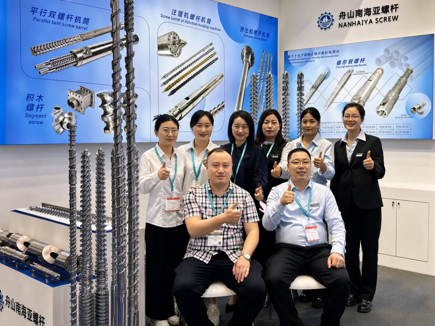
Related Articles
More insights on screw barrel technology and plastics processing.

PVC Profile Extruder Stripped Down: Screws, Dies, and Defect Fixes
Nov 3, 2026
PVC profile extruder guide covering screw types, die design, temperature control, defect troubleshooting, and sizing advice for window frames, trunking, and trims.
Read Article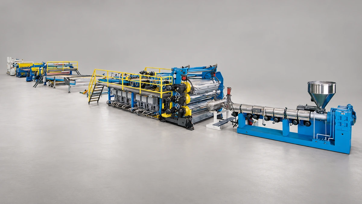
Sheet Extrusion Troubleshooting: Trace Every Defect to Its Root Cause
Nov 2, 2026
Master sheet extrusion troubleshooting with a systematic defect diagnosis framework. Fix orange peel, gauge variation, gels, flatness issues, and co-extrusion problems fast.
Read Article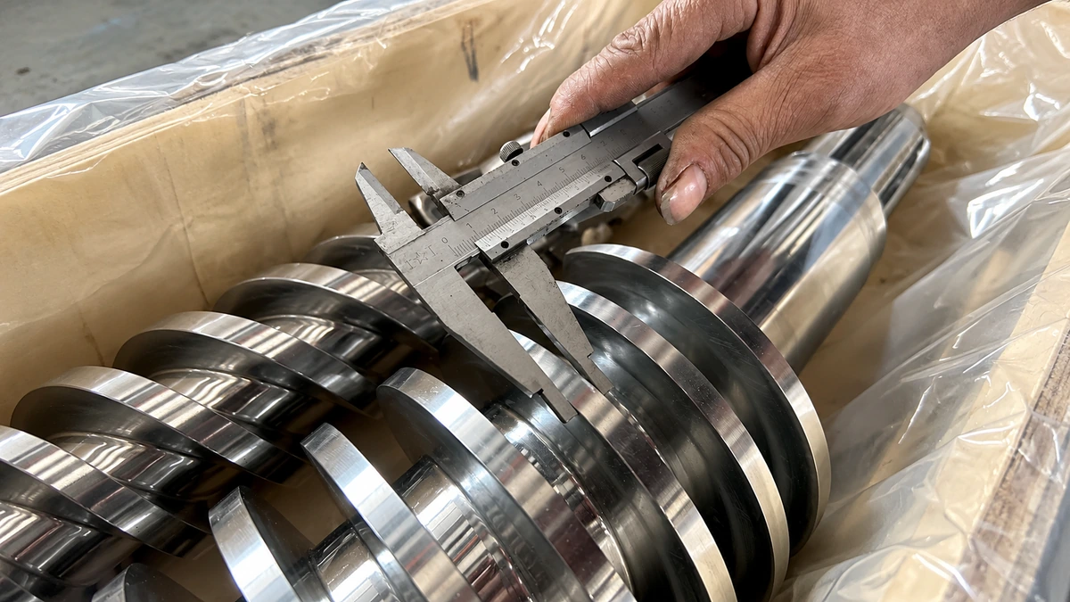
Extrusion Screw Compression Ratio: The Math Most Processors Get Wrong
Nov 2, 2026
Learn how to calculate extrusion screw compression ratio correctly, compare geometric vs. effective ratios, and match compression to every common thermoplastic.
Read ArticleLooking for something else?
Search by material, symptom or product and jump straight to the relevant page.
These are navigation suggestions based on keyword matching — not a quotation, not a delivery commitment, and not a substitute for engineering review. Final specification is confirmed by our engineers against your drawings and processed material.
Need help with screw barrel selection?
Share your machine model, processed material and application. Our team can help with pricing and technical support.