

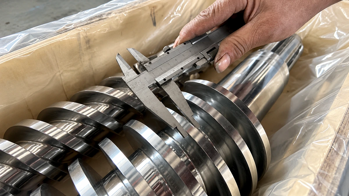
What Extrusion Screw Compression Ratio Really Means
Ask three process engineers to explain extrusion screw compression ratio and you'll likely get three answers of varying depth. Some recite a quick formula. Others wave vaguely toward the screw's transition zone. The reality is straightforward, yet surprisingly misunderstood on production floors worldwide.
Defining Compression Ratio in Plain Terms
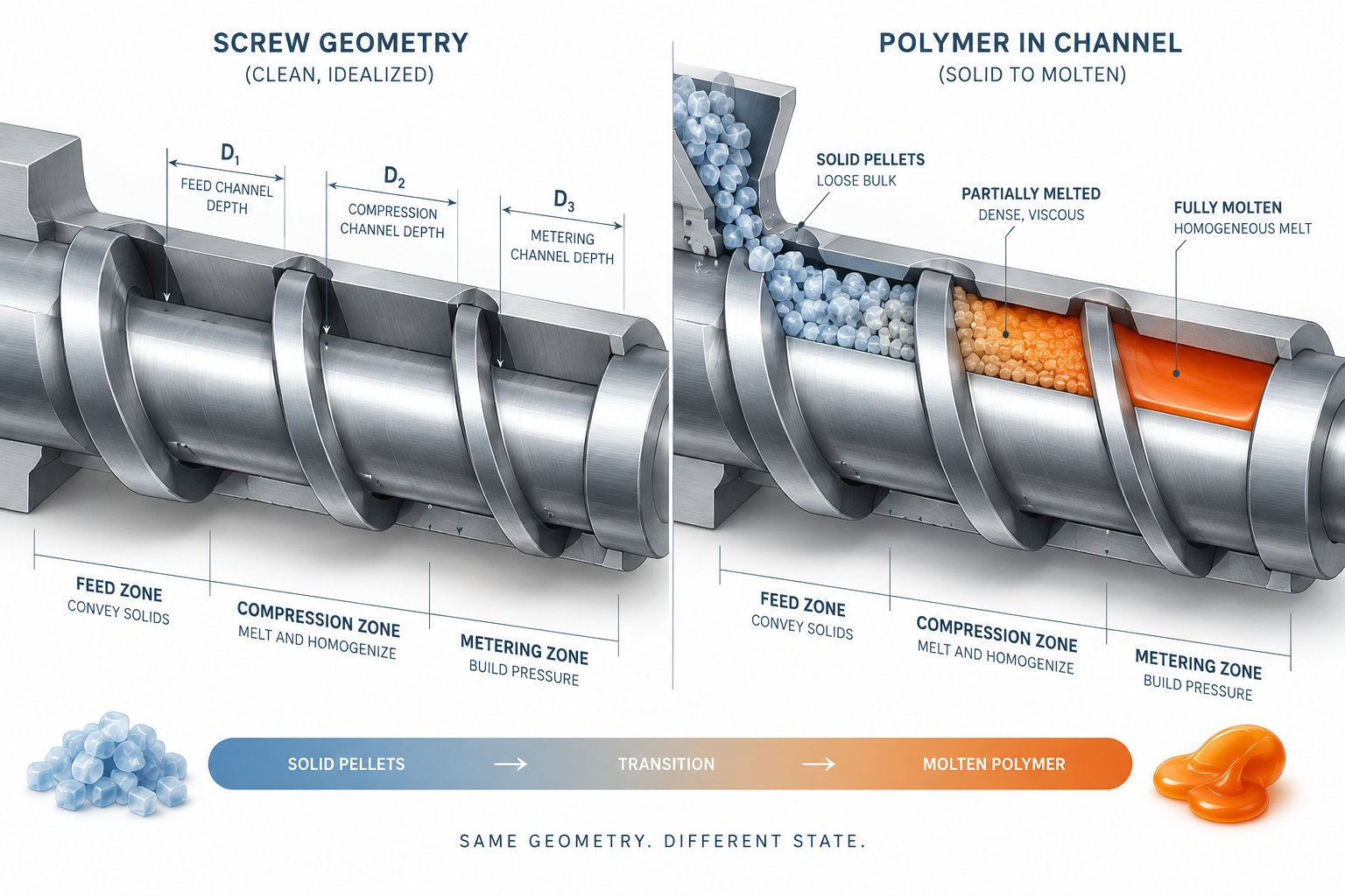
Extrusion screw compression ratio is the ratio of the channel depth in the feed zone (H1) to the channel depth in the metering zone (H2). Expressed as CR = H1 / H2, it quantifies how much the screw's channel volume decreases from the point where solid pellets enter the extruder feed barrel to the point where fully molten polymer exits toward the die.
Imagine squeezing a handful of loose pellets into a progressively tighter space. That tightening is exactly what the decreasing channel depth achieves along the screw's length. A ratio of 3:1, for instance, means the feed channel is three times deeper than the metering channel, so the material experiences a threefold reduction in available volume as it travels forward through the extruder barrels.
Why This Parameter Controls Melt Quality
This single number quietly governs three outcomes that define process success: melting efficiency, melt homogeneity, and output consistency. A compression ratio that's too low for a given resin leaves pellets poorly compacted, trapping air that can cause splay, gels, and pressure instability. Too high, and the screw overfeeds the downstream sections, generating excessive shear heat, promoting degradation, and even plugging mixers. Extruder screw wear issues often accelerate under both extremes, as mismatched compression forces metal surfaces to absorb energy the polymer should be receiving.
The compression ratio also sets the pressure profile inside the transition zone, directly influencing where and how quickly solids convert into a uniform melt. When that pressure profile doesn't match the resin's bulk density and frictional behavior, every downstream quality metric suffers.
What This Guide Covers That Others Miss
Most resources stop at the H1/H2 formula and a short polymer table. This guide goes further. You'll find worked calculation examples at multiple complexity levels, the critical distinction between geometric and effective compression ratio, a deep dive into compression rate versus compression ratio, polymer-specific reference data covering everything from commodity resins to biopolymers, and a systems-level decision framework that ties compression ratio to L/D, flight geometry, and barrel configuration. Every section addresses a gap that no single competitor resource covers end to end.
The logical starting point is the math itself, and there's more to it than a simple division problem.
How to Calculate Extrusion Screw Compression Ratio Step by Step
Most spec sheets and textbooks present the compression ratio formula as a one-liner. In practice, though, the way you calculate it determines whether you get a rough approximation or a number that actually reflects what's happening inside the extrusion barrel. Below are two methods at different levels of detail, followed by an honest look at where both fall short.
Basic Channel-Depth Calculation Method
The simplest and most widely used approach treats compression ratio as a straightforward depth comparison. You only need two measurements from the extruder screw drawing or physical inspection:
- Measure the feed-zone channel depth (Hf). This is the distance from the screw root to the top of the flight in the first full turn of the feed section. Suppose you measure an Hf of 10 mm.
- Measure the metering-zone channel depth (Hm). Take the same measurement in the last full turn of the metering section. For this example, assume Hm is 2 mm.
- Divide feed depth by metering depth. CR = Hf / Hm = 10 / 2 = 5.0
A result of 5:1 tells you the channel volume shrinks roughly fivefold as material moves from intake to output. For a constant-pitch, single-flighted extruder screw, this quick calculation is a reasonable first pass. It's the method most operators rely on, and it works well enough when you're comparing screws of similar diameter and flight geometry.
But "well enough" leaves room for error, especially when screw diameters differ or flight widths vary between designs.
Volumetric Approach Accounting for Flight Geometry
A more precise method calculates the actual volume of one channel turn in the feed and metering zones, rather than relying on depth alone. This volumetric compression ratio accounts for the fact that the screw root diameter grows as the channel gets shallower, which slightly changes the cross-sectional area available to the polymer.
The channel volume per unit length in a barrel extruder system can be approximated with:
V = π × (D − H/2) × H
where D is the nominal screw diameter and H is the channel depth at the section of interest. Here's how to apply it:
- Establish your screw dimensions. Use a 50 mm diameter screw with Hf = 10 mm and Hm = 2 mm.
- Calculate feed-zone channel volume per unit length.
Vf = π × (50 − 10/2) × 10 = π × 45 × 10 = 450π mm² - Calculate metering-zone channel volume per unit length.
Vm = π × (50 − 2/2) × 2 = π × 49 × 2 = 98π mm² - Divide feed volume by metering volume.
CRvol = 450π / 98π ≈ 4.6
Notice the difference: the basic depth method returns 5.0, while the volumetric method yields approximately 4.6. That 8% gap comes from the geometric reality that the root diameter in the metering zone is larger than in the feed zone, slightly increasing the effective cross-sectional area at the shallow end. On smaller-diameter screws, this discrepancy is proportionally larger and can mislead screw selection if ignored.
You'll also find that flight width plays a role. Industry convention puts flight width at roughly 10% of barrel diameter. Wider flights reduce the open channel area available for polymer transport, meaning two screws with identical channel depths but different flight thicknesses won't compress material at the same effective rate. Although the standard formulas above omit flight width for simplicity, engineers working with non-standard flight proportions should factor this in when precision matters.
Where Simple Formulas Fall Short
Both methods above assume a conventional single-flighted, constant-pitch extruder screw with uniform flight geometry from feed to metering. In the real world, many modern screws break those assumptions:
- Variable-pitch designs achieve compression partly by tightening the flight spacing rather than only reducing channel depth. The H1/H2 ratio alone misses this contribution entirely.
- Barrier screws introduce a secondary flight that splits the channel into separate solids and melt passages, each with its own depth progression. Calculating a single compression ratio for these screws oversimplifies two distinct compression paths.
- Multi-stage (vented) screws decompress and recompress partway down the extrusion barrel, creating two separate compression events. A single ratio can't describe this behavior.
There's another, subtler limitation. The formulas treat the polymer as though it has a constant density from hopper to die. In reality, loose pellets entering the feed zone have a bulk density far lower than the melt density at the metering end. That density transition means the actual compression the polymer experiences differs from the geometric number on the spec sheet, sometimes significantly. A screw rated at 3:1 geometrically might behave closer to 2.5:1 or 3.5:1 depending on the specific resin's bulk-to-melt density ratio.
This gap between the calculated number and what the polymer actually feels inside the barrel is exactly where many processing problems originate, and it's the reason experienced engineers draw a sharp line between geometric and effective compression ratio.
Geometric vs. Effective Compression Ratio: What the Spec Sheet Doesn't Tell You
That gap between what the formula says and what the polymer actually experiences inside the barrel? It has a name. Engineers call it the difference between geometric compression ratio and effective compression ratio, and confusing the two is one of the most common sources of screw extrusion problems that never get properly diagnosed.
Geometric Ratio from the Spec Sheet
The geometric compression ratio is the number you calculated in the previous section: Hf / Hm, pure metal geometry, completely independent of whatever polymer you run through the machine. Order a plastic extruder screw with a 3.0:1 compression ratio and you'll get exactly that ratio whether you feed it HDPE pellets, powdered PVC, or recycled flake. The screw doesn't change shape based on resin selection.
This is the number on every spec sheet, every purchase order, and every CAD drawing. It's useful as a design starting point and a standardized way to compare screw geometries. But here's the catch: it describes the machine, not the process. Two extrusion screws with identical 3:1 geometric ratios, identical diameters, and identical L/D values can produce wildly different melt quality when processing different resins, or even different grades of the same polymer family.
The reason lies in what happens between the metal surfaces.
Effective Ratio in Real Processing Conditions
The effective compression ratio accounts for the actual volume reduction the polymer undergoes as it transitions from loose solid feedstock to a dense, pressurized melt. Three factors drive the wedge between geometric and effective values:
- Bulk density vs. melt density transition. Loose pellets entering the feed zone typically occupy far more space than the same mass of molten polymer. HDPE pellets, for instance, have a bulk density around 590 kg/m3 but a melt density near 760 kg/m3. That means the polymer naturally densifies by roughly 29% as it melts, independent of any channel-depth change. A resin with a smaller bulk-to-melt density gap, like amorphous polystyrene, undergoes less natural densification, so the screw's geometry must do more of the compression work. Experimental extrusion studies on LLDPE confirm that feedstock bulk density directly dictates the compression ratio needed to keep the metering channel full and pressurized.
- Leakage flow over flights. No flight-to-barrel seal is perfect. Molten polymer bleeds backward over the flight lands, reducing the net forward flow. Research on leakage-flow models demonstrates that this backflow is highly dependent on the shear-thinning behavior of the melt and the flight clearance geometry. For pressure-generating metering zones, leakage reduces net throughput, effectively lowering the compression the polymer experiences. For screws with worn flights or intentionally undercut barriers, the leakage effect is even more pronounced.
- Drag-flow variations with viscosity. The traditional pumping model assumes the barrel drags material forward at a rate proportional to screw speed. In reality, polymer viscosity drops sharply with increasing temperature and shear rate. As the melt heats up along the transition zone, its resistance to flow changes, altering the actual volumetric throughput at each point along the screw. A highly shear-thinning resin will behave differently from a more Newtonian fluid even in geometrically identical channels.
The net result is that the effective compression ratio is a dynamic, resin-dependent number that shifts with processing conditions, while the geometric ratio remains fixed in steel.
| Characteristic | Geometric Compression Ratio | Effective Compression Ratio |
|---|---|---|
| Definition | Feed channel depth divided by metering channel depth (Hf / Hm) | Actual volume reduction the polymer experiences, accounting for density changes, leakage, and flow behavior |
| Depends on polymer? | No — purely a function of screw metal geometry | Yes — varies with bulk density, melt density, viscosity profile, and pellet form |
| Changes with processing conditions? | No — fixed unless the screw is physically modified | Yes — shifts with barrel temperature, screw speed, backpressure, and flight wear |
| Where you find it | Spec sheets, screw drawings, purchase orders | Calculated from process data or inferred from melt quality diagnostics |
| Primary use | Screw specification, comparison shopping, initial design parameter | Process optimization, troubleshooting melt defects, predicting real output behavior |
| Typical accuracy for predicting melt quality | Rough guideline only — can mislead across different polymers | Much closer to actual process behavior when properly estimated |
Why Experienced Engineers Look Beyond H1 over H2
Consider a practical scenario. You're running an extrusion screw with a 2.8:1 geometric compression ratio on LLDPE pellets with a bulk density around 590 kg/m3. The process runs well: the metering channel stays full, pressures are stable, and melt quality is excellent. Research from Dow engineers confirms that 2.8 is optimal for LLDPE pellet feedstocks in this configuration.
Now swap that feedstock for recycled LLDPE flake with a bulk density of 350 kg/m3. The geometric ratio hasn't changed — you're using the same screw. But the effective compression ratio has dropped dramatically because the lower bulk density means each channel turn captures far less mass. The feed section can no longer deliver enough material to keep the metering zone full and pressurized. Output falls, pressure fluctuates, and melt quality deteriorates. The fix isn't a process tweak; it's a deeper feed channel, which means a higher geometric compression ratio to restore the effective ratio the polymer needs.
This is exactly why running ABS resin on a screw designed for HIPS, or vice versa, creates problems even though both are styrenics processed at similar temperatures. Their bulk densities and solids conveying behaviors differ enough to shift the effective compression ratio out of the optimal window.
The takeaway for processors is simple but often overlooked: the geometric ratio printed on a spec sheet is a starting point, not a guarantee. Matching that number to a specific polymer requires understanding how bulk density, melt density, and viscosity interact inside the barrel. And even when the geometric ratio is well-chosen, the rate at which compression occurs along the transition zone introduces yet another variable that many engineers underestimate.
The Physics Behind Polymer-Specific Compression Ratios
Bulk density, melt density, and viscosity don't just shift the effective compression ratio on paper — they dictate distinct physical demands inside every extruder process. Understanding why different polymers need different compression ratios requires a look at three intersecting material properties: crystallinity-driven density changes, thermal stability limits, and viscous energy generation. Each one pushes the ideal ratio in a different direction, and ignoring any of them leads to screw selections based on guesswork rather than physics.
Bulk Density and Crystallinity Effects
The gap between a polymer's bulk density as solid feedstock and its melt density determines how much volume reduction the screw must achieve. Semicrystalline polymers undergo the largest density swing because their ordered crystalline regions pack far more tightly once melted and recrystallized structures collapse. HDPE, with crystallinity levels often above 60%, enters the feed zone as pellets with a bulk density around 590 kg/m3 and melts to roughly 760 kg/m3. That substantial densification requires a higher compression ratio — typically 3.0:1 to 4.5:1 — to fully consolidate the solids bed and keep the metering zone pressurized.
Amorphous polymers tell a different story. Polystyrene pellets, for example, already sit closer to their melt density because there's no crystalline structure to collapse. The volume change during melting is modest, so the extruder screws and barrels don't need to squeeze as aggressively. A ratio in the 2.0:1 to 3.0:1 range is generally sufficient. Push higher and you risk over-compressing the melt, generating unnecessary shear energy with no benefit to solids conveying.
- High-crystallinity resins (HDPE, POM, PA66): Large bulk-to-melt density gap demands higher compression ratios (3.0:1 – 4.5:1) to eliminate voids and maintain metering-zone pressure.
- Medium-crystallinity resins (PP, LLDPE, PET): Moderate density transition allows mid-range ratios (2.5:1 – 3.5:1), balancing compaction with manageable shear.
- Amorphous resins (PS, PC, PMMA, ABS): Minimal density change permits lower ratios (2.0:1 – 3.0:1), as the solids bed already approximates melt-phase packing.
Heat Sensitivity and Degradation Risk
Some polymers can't tolerate the mechanical energy that high compression ratios generate — regardless of what their density profile might suggest. PVC is the textbook example. Its thermal degradation window is narrow: processing typically occurs between 160 °C and 200 °C, and exceeding those limits triggers dehydrochlorination and rapid breakdown. Simulation research on PVC twin-screw extrusion demonstrates that screw configurations with lower compression ratios improve throughput while keeping melt temperatures within safe boundaries. The high viscosity of PVC compounds this challenge, because aggressive compression generates intense internal friction that barrel cooling alone cannot always offset.
This is why PVC screws typically use compression ratios of only 1.5:1 to 2.5:1 — values that seem low compared to polyolefins but are essential for preventing thermal damage. Similar caution applies to PVDC, certain bio-based polymers, and highly plasticized compounds where molecular chains are vulnerable to shear-induced scission. Effective extrusion controls for these materials mean deliberately limiting the compression the screw imposes, even if doing so sacrifices some solids-conveying efficiency.
Shear Heating and Energy Consumption Trade-Offs
Every increment of compression ratio increases viscous dissipation — the conversion of mechanical drive energy into heat within the polymer melt. Imagine the melt being forced through a progressively narrower channel: the velocity gradients across that channel steepen, shear rates climb, and friction between polymer chains converts kinetic energy into thermal energy. This is the thermodynamic cost of compression.
For high-viscosity resins like polycarbonate or high-molecular-weight HDPE, the effect is amplified. Their resistance to flow is already substantial, so squeezing them through a deep-compression screw generates disproportionate shear heating. The practical consequences are measurable:
- Elevated melt temperature: Exceeding the target exit temperature degrades surface finish, reduces mechanical properties, and narrows the processing window for downstream operations.
- Increased motor load: The extruder drive must supply more torque to push viscous material through tighter channels, raising energy consumption per kilogram of output. Industry analysis confirms that shear heating is a direct function of the compression ratio, as it governs shear rates throughout the screw.
- Reduced thermal uniformity: Shear heating is not evenly distributed — it concentrates near the barrel wall and flight tips, creating hot spots that can degrade sensitive additives or colorants even when average melt temperature appears acceptable.
The implication is a fundamental trade-off. Higher compression ratios improve solids compaction and melting completeness, but they also dump more energy into the melt as heat. For polymers that can absorb that energy — like LDPE or PP with broad processing windows — a moderately high ratio improves productivity. For heat-sensitive or high-viscosity resins, the same ratio creates problems that no amount of downstream cooling can fully correct.
Selecting the right compression ratio, then, is never just about matching a bulk density number. It's a balance between three competing physical demands: compaction, thermal safety, and energy efficiency. And even when that balance is struck perfectly, how fast the screw achieves that compression — over a few turns or many — introduces a separate variable with its own set of consequences.
Compression Rate: The Extruder Screw Barrel Variable Hiding in Plain Sight
Two screws sit side by side on a workbench. Both have identical 3:1 compression ratios, the same metering depth, and the same overall L/D. Install the first in your extruder system and you get stable melt pressure, clean extrudate, and consistent output. Install the second and you're chasing surging, finding unmelted particles in the product, and watching pressure traces oscillate wildly. Same ratio, completely different results. The culprit? Compression rate.
Defining Compression Rate Versus Compression Ratio
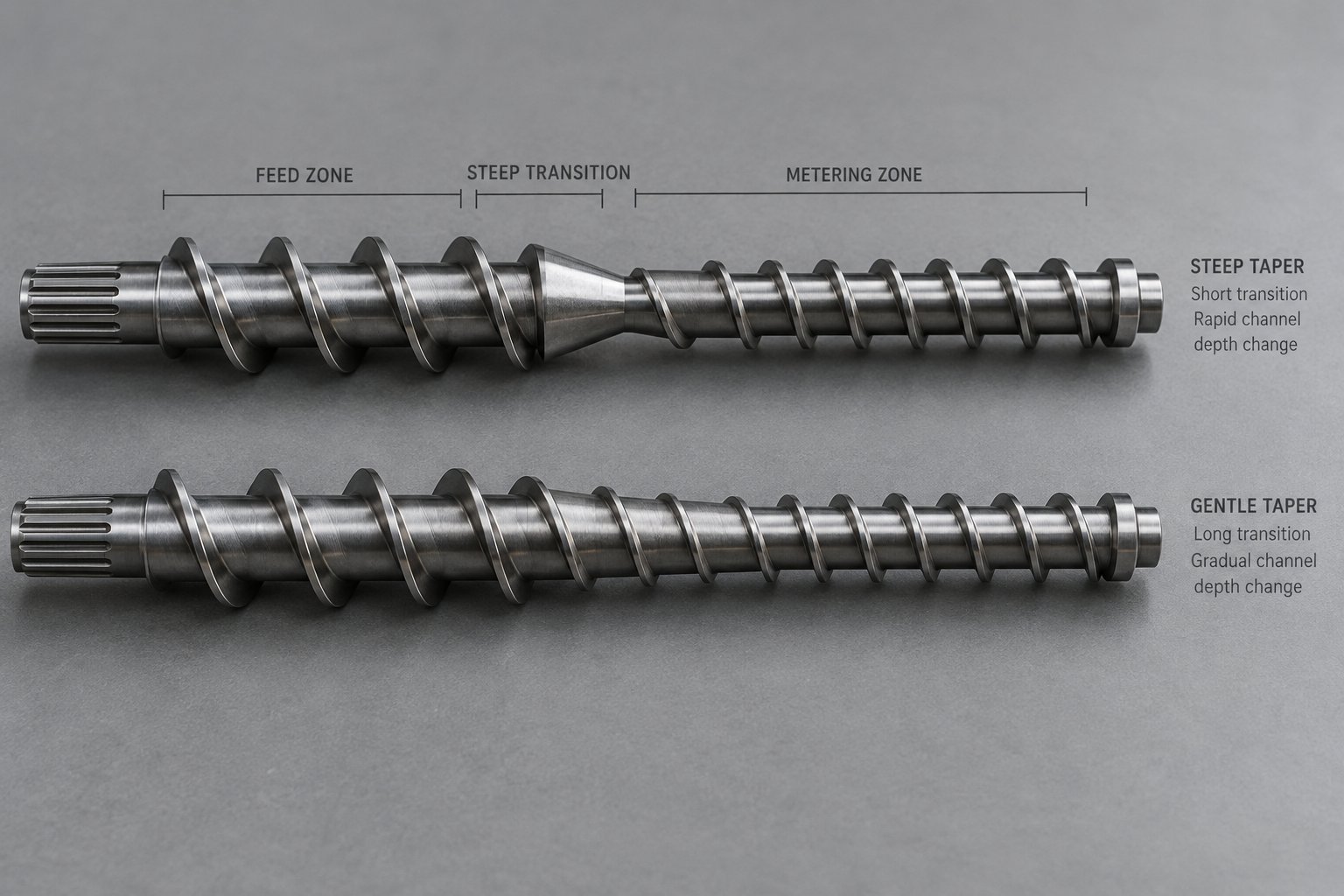
Compression ratio tells you how much the channel depth changes from feed to metering. Compression rate tells you how quickly that change happens across the transition zone. It's measured as the depth reduction per screw turn — essentially the slope of the channel-depth taper rather than just the endpoints.
Compression ratio is the destination. Compression rate is the speed of the journey. Two screws can arrive at the same endpoint while taking dramatically different paths — and those paths determine whether the polymer melts uniformly or breaks apart into fragments.
The formal calculation, as presented in single-screw extrusion performance research, defines compression rate as:
R = (Hf − Hm) / (M × L × sin θb)
where Hf is the feed channel depth, Hm is the metering channel depth, M is the number of turns in the transition section, L is the lead length, and θb is the helix angle at the barrel wall. For a quick mental model, though, you can simplify it to the depth change divided by the number of transition turns: (Hf − Hm) / M.
Imagine two screws, both with a 9 mm feed depth and a 3 mm metering depth — a 3:1 ratio. Screw A compresses over 4 transition turns, giving a rate of (9 − 3) / 4 = 1.5 mm per turn. Screw B spreads the same depth change over 10 turns: (9 − 3) / 10 = 0.6 mm per turn. Screw A squeezes the polymer more than twice as aggressively per revolution, even though any extruder drawing would show the same compression ratio printed on both spec sheets.
How Transition Zone Length Changes Everything
The transition zone is where the real work of melting happens. Solid pellets compact against the barrel wall, form a solid bed, and progressively convert into a melt pool that grows turn by turn. The rate at which the channel depth decreases directly controls the pressure buildup in this critical region — and pressure, in turn, governs melting performance.
An aggressive compression rate — depth dropping steeply over just a few turns — ramps up channel pressure quickly. That spike forces the solid bed downstream faster than the melting flux can consume it. Experimental data from instrumented extrusion barrels shows that when channel pressure peaks sharply near the end of the transition section, the solid bed can break apart, sending unmelted fragments into the metering zone and out through the die. The result is the translucent white streaks and irregular solid inclusions visible in cross-sectioned extrudate — defects that no amount of downstream mixing fully eliminates at high rates.
A gradual compression rate takes the opposite approach: the channel narrows gently over many turns, giving the melting flux more barrel surface area and more time to work through the solid bed. Pressure builds steadily rather than spiking. The solid bed remains intact longer, which actually helps melting because a coherent bed maintains better contact with the barrel wall than a fragmented one.
But gradual isn't always better. Spreading compression over too many turns wastes valuable barrel length that could be allocated to a longer metering zone for better melt homogeneity, or to a mixing section for dispersing additives. In a fixed-length extruder system, every extra turn devoted to a leisurely transition is a turn stolen from somewhere else. The goal is finding the rate that matches the polymer's melting behavior — fast enough to use barrel length efficiently, slow enough to avoid solid bed breakup.
Signs of Mismatched Compression Rate in Production
Because compression rate problems masquerade as other issues, they're frequently misdiagnosed. Here are the telltale symptoms to watch for on the production floor:
- Pressure surging at the die: Cyclical oscillations in discharge pressure — often with periods of 15 to 30 seconds — are a classic indicator. Troubleshooting research identifies poor solids conveying and melting instabilities as primary causes, and an overly aggressive compression rate amplifies both by creating pressure spikes that destabilize the solid bed.
- Unmelted particles ("unmelt") in the extrudate: Solid polymer fragments appearing in finished products point to a melting capacity that can't keep up with throughput. While reducing screw speed is the short-term fix, the root cause is often a compression rate that forces material through the transition zone faster than the barrel surface can melt it.
- Erratic motor current: When the solid bed alternately compacts and breaks apart due to an aggressive compression rate, the torque demand on the drive fluctuates in sync, showing up as motor-current swings even at constant screw speed.
- Elevated discharge temperature at moderate speeds: A steep compression rate concentrates shear energy in a short section, creating localized overheating. You'll notice discharge temperatures climbing above target well before you reach the screw's rated speed — a warning sign that compression is happening too abruptly.
The tricky part is that all of these symptoms can also result from other causes: a hot feed casing, inadequate screw cooling, or simply running the wrong compression ratio for the resin. The distinguishing clue is pattern: compression-rate problems tend to appear specifically as screw speed increases, because higher speeds amplify the mismatch between solids conveying capacity and melting flux. Experimental extrusion data consistently shows that solid polymer fragments become progressively worse at higher screw speeds when the compression geometry is mismatched, because the melting flux increases only by a factor of about 1.4 when screw speed doubles, while solids conveying capacity doubles outright.
Recognizing that compression rate and compression ratio are independent design parameters — each requiring separate optimization for every polymer and production target — is what separates a screw specification from a screw design. The next logical question becomes: for a given polymer, what combination of ratio and rate actually works? Answering that requires a comprehensive reference that maps both parameters across the full range of commercial thermoplastics.
Screw Compression Ratio Chart for Every Common Thermoplastic
Knowing that compression ratio and compression rate are independent variables is valuable. Knowing which values to start with for a specific polymer is what actually gets your line running. The tables below consolidate general industry guidance into a single screw compression ratio chart covering commodity resins, engineering plastics, and specialty materials — including categories like recycled feedstocks and biopolymers that most references ignore entirely.
A quick but important disclaimer before you reference these numbers: the ranges listed are general starting points based on widely accepted thermoplastic extrusion screw design practice. Actual values depend on specific resin grades, filler content, additive packages, pellet versus powder form, and production targets. Treat them as a calibrated first guess, not a final specification.
Standard Thermoplastics Compression Ratio Reference
Commodity resins account for the vast majority of extrusion output worldwide, and their compression ratio ranges are the most well-established. Even so, you'll notice meaningful variation within families — LDPE and HDPE, for instance, land in different zones because their crystallinity and bulk density profiles diverge significantly. Industry experts confirm that PE screws typically use a 3:1 ratio as a starting point, while nylon screws typically start at 4:1, with adjustments driven by the extruder screw design parameters discussed in previous sections.
| Polymer | Typical Compression Ratio Range | Relative Bulk Density | Heat Sensitivity | Processing Notes |
|---|---|---|---|---|
| LDPE | 3.0:1 – 4.0:1 | Low-medium | Low | Broad processing window; higher ratios tolerated well due to low viscosity and good thermal stability. |
| LLDPE | 2.8:1 – 3.5:1 | Medium | Low | Slightly lower than LDPE due to higher viscosity and greater shear sensitivity; 2.8:1 often optimal for pellet feedstocks. |
| HDPE | 3.0:1 – 4.5:1 | Medium | Low | High crystallinity demands more compression to consolidate solids bed; grooved feed barrels may require ratio adjustment. |
| PP (homopolymer) | 2.5:1 – 3.5:1 | Medium | Low-moderate | Lower melt viscosity than HDPE allows moderate ratios; random copolymer grades lean toward lower end. |
| PS (GPPS / HIPS) | 2.0:1 – 3.0:1 | Medium-high | Low-moderate | Amorphous structure means small bulk-to-melt density gap; over-compression generates unnecessary shear heat. |
| PVC (rigid) | 1.5:1 – 2.5:1 | Variable (powder vs. pellet) | High | Narrow thermal window; aggressive compression causes degradation. Powder forms need carefully matched feed depth. |
| PVC (flexible) | 2.5:1 – 3.5:1 | Medium | High | Plasticizer content lowers viscosity, permitting somewhat higher ratios than rigid PVC, but thermal limits still apply. |
| PET | 2.5:1 – 3.5:1 | Medium-high | Moderate | Moisture-sensitive; must be dried thoroughly. Excessive shear increases acetaldehyde generation in packaging applications. |
| ABS | 2.0:1 – 3.0:1 | Medium-high | Moderate | Amorphous; rubber-phase morphology is shear-sensitive. Over-compression can degrade impact properties. |
Engineering and High-Performance Polymers
Engineering resins bring tighter processing windows and higher melt viscosities into the equation. The extruder screw design parameters for these materials often lean toward moderate compression ratios to control shear heating, even when crystallinity levels might otherwise suggest going higher. Nylon is a notable exception — its high crystallinity and large density swing during melting push starting ratios above those of most commodity resins.
| Polymer | Typical Compression Ratio Range | Relative Bulk Density | Heat Sensitivity | Processing Notes |
|---|---|---|---|---|
| PA6 (Nylon 6) | 3.5:1 – 4.0:1 | Medium | Moderate | High crystallinity and sharp melting point; requires thorough drying. Rapid melting benefits from controlled compression rate. |
| PA66 (Nylon 66) | 3.5:1 – 4.5:1 | Medium | Moderate | Similar to PA6 but with a higher melting point (~260 °C); slightly more compression helps consolidate the solids bed at higher thermal input. |
| PC (Polycarbonate) | 2.0:1 – 2.8:1 | Medium-high | Moderate-high | High melt viscosity generates significant shear heat; lower ratios protect optical clarity and color stability. |
| PMMA (Acrylic) | 2.0:1 – 3.0:1 | Medium-high | Moderate | Amorphous; sensitive to bubbles and moisture-induced splay. Moderate compression avoids thermal yellowing. |
| TPU | 2.0:1 – 3.0:1 | Medium | Moderate-high | Elastic melt behavior complicates pumping; low ratios reduce die-swell variability and prevent thermal crosslinking. |
| PEEK | 2.5:1 – 3.5:1 | Medium-high | Low (high Tm) | Extremely high processing temperatures (~380 °C); ratio selection driven by viscosity and crystallization kinetics rather than thermal degradation risk. |
Specialty Applications Including Recycled and Bio-Based Resins
This is where standard charts fall short — and where many processors run into trouble. Recycled plastics introduce wildly variable bulk densities, mixed-polymer contamination, and inconsistent pellet geometry. Biopolymers like PLA and PHA bring narrow thermal windows that rival or exceed PVC in sensitivity. And highly filled compounds change the wear equation entirely, as research on thermoplastic composites demonstrates that improperly optimized volumetric compression ratios for filled resins cause extreme abrasive wear on the screw root. The extrusion screw compression ratio alone doesn't capture these challenges — but it remains the starting framework.
| Material Category | Typical Compression Ratio Range | Relative Bulk Density | Heat Sensitivity | Processing Notes |
|---|---|---|---|---|
| PLA (Poly-lactic acid) | 2.5:1 – 3.5:1 | Medium-high | Moderate-high | Semi-crystalline grades need more compression than amorphous. Sensitive to moisture and residence time; excessive shear causes molecular weight loss. |
| PHA / PHBV | 2.5:1 – 3.0:1 | Medium-high | High | Decomposition temperature sits dangerously close to the melting point. Studies on PHA extrusion coating confirm that melt temperatures must stay below 185 °C, demanding gentle compression profiles. |
| Recycled PE/PP (pellet) | 3.0:1 – 4.0:1 | Low-medium (variable) | Low-moderate | Lower and inconsistent bulk density often requires deeper feed zones. Mixed-resin batches may need compression ratios determined separately from standard values. |
| Recycled PE/PP (flake/regrind) | 3.5:1 – 5.0:1 | Low (highly variable) | Low-moderate | Flake geometry traps air and bridges in the feed throat. Very deep feed channels and higher ratios compensate for poor packing density. |
| Mixed recycled polymers | Case-specific | Highly variable | Variable | No standard ratio applies. Industry experts recommend determining feeding and melting requirements separately rather than relying on standard values. |
| Highly filled compounds (>30% filler) | 1.5:1 – 2.5:1 | High (dense fillers raise it) | Variable (matrix-dependent) | Fillers increase effective bulk density, reducing the need for compression. Over-compression accelerates abrasive wear on flights and screw root. Hardened screw surfaces essential. |
Notice how recycled flake and regrind can push ratios well above 4:1, while heavily filled compounds pull them below 2.5:1 — a range spanning more than double from low end to high. This spread illustrates why a single "recommended ratio" for any broad material category is inherently imprecise. Grade-specific data, actual bulk density measurements, and target melt conditions should always override a chart lookup.
These tables provide a solid foundation for screw selection, but a question still lingers for processors who work across both extrusion and injection molding: do the same ratio ranges apply when the screw reciprocates instead of rotating continuously? The answer introduces an entirely separate set of design priorities.
Injection Screw vs. Extrusion Screw: Why Compression Ratios Don't Translate Directly
The H1/H2 formula is universal — it works for any plasticating screw regardless of machine type. Yet applying a compression ratio that performs flawlessly in extrusion to an injection molding screw, or vice versa, routinely causes problems. The reason comes down to how each machine uses that screw, and the differences run deeper than most online resources acknowledge.
Continuous vs. Reciprocating Screw Operation
An extrusion screw rotates continuously in a fixed axial position. Polymer enters the feed zone, melts through the transition, and exits the metering section in a steady stream. The screw's only job is to plasticate and pump — nonstop, one direction, at a relatively constant throughput.
A reciprocating screw design in injection molding does something fundamentally different. During the recovery phase, it rotates to plasticate material and accumulate a shot of melt in front of the screw tip. Then it stops rotating and drives forward like a plunger to inject that melt into a mold cavity. This dual-function cycle — part plasticator, part hydraulic ram — changes every assumption about how compression behaves during operation.
Consider what happens during shot recovery. As molten polymer accumulates ahead of the screw, backpressure resists the screw's rearward travel, forcing the melt to work against an adjustable hydraulic or electromechanical load. That resistance directly affects how completely the polymer compresses and homogenizes in the metering zone. Increase backpressure and you effectively raise the compression the melt experiences — even without changing screw geometry. Decrease it and the screw recovers faster but delivers a less uniform melt.
Extrusion has no equivalent mechanism. Die-head pressure provides some resistance, but it doesn't cycle on and off, and the screw never reverses direction.
How Injection Molding Changes Compression Design Priorities
The injection molding screw compression ratio must account for variables that simply don't exist in extrusion. A non-return valve (check ring) sits at the screw tip, and its sealing behavior during injection influences how much melt leaks backward — altering the effective compression the polymer experienced during recovery. Decompression (suck-back) after recovery relieves pressure to prevent drool at the nozzle, but excessive decompression pulls air into the melt stream, causing splay and bubbles in finished parts. These cyclic pressure swings mean the melt is never in the steady-state flow regime that extrusion screws are designed around.
The practical result is that injection screws tend to use slightly lower compression ratios than their extrusion counterparts for the same polymer. Backpressure provides supplemental compression that barrel geometry alone must supply in extrusion, and the shorter effective plasticating length (since part of the screw retracts during recovery) limits how aggressively the transition zone can compress material.
| Design Factor | Extrusion Screw | Injection Molding Screw |
|---|---|---|
| Operation mode | Continuous rotation, fixed axial position | Intermittent rotation with axial reciprocation |
| Compression ratio calculation | H1/H2 — same formula | H1/H2 — same formula |
| Typical ratio range (general-purpose) | 2.5:1 – 4.0:1 depending on polymer | 2.0:1 – 3.5:1 depending on polymer; backpressure supplements compression |
| Backpressure influence | Die pressure only — relatively constant during steady-state operation | Adjustable backpressure during recovery adds supplemental melt compression and mixing |
| Check ring / non-return valve | Not present | Present — leakage past the check ring alters effective compression during injection |
| Decompression cycle | None | Suck-back after recovery relieves pressure but risks air entrainment if excessive |
| Effective plasticating length | Full screw length available at all times | Varies with shot size — screw retraction shortens the active feed and transition zones |
| Primary design priority | Maximize steady-state melt quality and output rate | Balance melt quality with shot-to-shot consistency, recovery time, and injection repeatability |
The key takeaway? While the math is identical, the engineering context is not. A 3:1 ratio on an extrusion screw delivers a fixed, predictable compression profile every second of operation. That same 3:1 on an injection screw interacts with backpressure settings, shot size, recovery speed, and check-ring condition — all of which shift the effective compression from cycle to cycle. Processors who run both machine types should resist the temptation to swap screw specs between platforms without accounting for these differences.
This distinction between extrusion and injection molding also hints at a broader truth: the simple H1/H2 formula, no matter how accurately calculated, captures only a fraction of what modern screw technology actually does. Barrier flights, vented multi-stage layouts, and variable-pitch geometries all achieve compression through mechanisms that a single depth ratio was never designed to describe.
Barrier Screw Design and Advanced Geometries Beyond H1 over H2
A single-flight, constant-pitch screw is the simplest geometry to describe — and the only one the H1/H2 formula was ever meant to handle. Yet walk through any modern extrusion plant and you'll find screws with secondary barrier flights, multi-stage vented layouts, and variable-pitch channels, none of which compress material through channel depth alone. Trying to characterize these designs with a single depth ratio is like describing a car's performance using only its top speed: it captures one data point while missing the entire driving experience.
Understanding how these advanced geometries achieve compression — and why they often outperform conventional designs — requires looking at three distinct categories of modern screw technology.
Barrier Flight Screws and Dual-Channel Compression
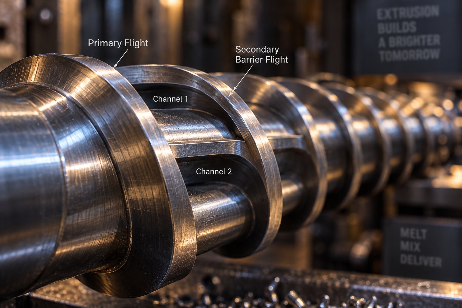
Imagine splitting the screw channel into two parallel pathways: one dedicated to unmelted solids, the other reserved exclusively for molten polymer. That's exactly what a barrier screw design does. A secondary flight — the barrier flight — runs alongside the primary flight through the transition zone, creating separate solids and melt channels with independent depth progressions.
In a conventional single-flight screw, solids and melt share the same channel. As the melt pool grows, it coexists with the shrinking solid bed, and if that bed fractures (a phenomenon called solid-bed breakup), fragments of unmelted polymer get carried into the metering zone. Extrusion expert Jim Frankland explains that barrier screws essentially eliminate this problem because solids remain trapped in the solids channel until they melt and pass over the barrier flight into the melt channel. The result is a more thermally homogeneous melt exiting the screw — without needing a restrictive mixing section to finish the job.
Here's where the H1/H2 formula breaks down. In a barrier screw, the solids channel and melt channel each have their own depth profile. The solids channel typically starts deep and narrows progressively, forcing the bed against the barrel wall to maximize heat transfer. The melt channel, meanwhile, starts shallow and deepens as it collects molten polymer from over the barrier flight. You're looking at two compression behaviors happening simultaneously, in parallel, within the same screw — a reality that no single ratio can describe.
Barrier designs do introduce unique extruder screw wear issues, though. If the solids channel's compression rate is too gradual, the solid bed can still break apart due to melt undermining its structural integrity. The broken fragments collect at the narrowing end of the solids channel, creating a plug. Since the surrounding melt offers no opposing pressure, the resulting force pushes the screw sideways against the barrel wall. Frankland documented one 8-inch barrier screw where this phenomenon generated an estimated 350,000 lb of localized force — enough to bend the screw shaft and wear flights completely down to the root diameter over a span of roughly five diameters. The wear pattern is distinctive: concentrated on one side of the barrel at the end of the barrier section, rather than evenly distributed as you'd see in a conventional screw with generalized abrasion.
Multi-Stage and Vented Screw Designs
What happens when your polymer carries moisture, trapped volatiles, or residual monomers that must escape before the melt reaches the die? A single compression event from feed to metering won't solve the problem. Multi stage screw extrusion tackles this by essentially stacking two (or even three) screws end-to-end on the same shaft, with a decompression zone between them where the barrel includes an open vent port.
The first stage behaves like a conventional screw: it compresses, melts, and pressurizes the polymer. Then, instead of pumping directly toward the die, the channel abruptly deepens again, dropping melt pressure to atmospheric levels. This decompression allows volatiles to escape through the vent opening. The second stage re-compresses the now-degassed melt and pumps it forward to overcome die-head pressure.
As vented extrusion specialists at SpiraMelt Technologies explain, the second stage must be designed to accommodate a higher output capacity than the first to ensure the vent zone channels remain only partially filled. If the second stage can't move melt forward fast enough, pressure builds in the vent section and molten polymer floods out the vent port — a costly and labor-intensive problem to remedy.
The compression ratio challenge here is obvious: which ratio do you specify? The first stage has its own feed depth and pre-vent metering depth. The second stage starts with a new "feed" depth at the vent zone and ends with its own metering depth. Quoting a single H1/H2 number for a vented screw is technically meaningless — you need two separate ratios, each optimized for different tasks. The first stage must fully melt the polymer and build enough pressure to feed a mixing element or restriction before the vent. The second stage must re-pressurize a melt-fed channel without excessive shear, since the polymer is already fully molten.
Adding to the complexity, longer L/D ratios are essential for vented designs to provide sufficient axial length for the vent section, mixing elements, and adequate second-stage pumping — all without sacrificing throughput. Even with longer barrels, every turn devoted to decompression and volatile removal is a turn unavailable for melting or homogenization, making efficient compression in each stage critically important.
Variable-Pitch and Mixed-Geometry Approaches
Conventional screws achieve compression by reducing channel depth while keeping the flight pitch (the axial distance between successive flights) constant. A variable pitch extruder screw flips this logic — or, more commonly, combines both strategies simultaneously. By tightening the flight spacing along the transition zone, the screw reduces the volume of each successive channel turn even if the depth doesn't change as dramatically.
Think of it this way: if you shorten the distance between flights from 60 mm to 40 mm while holding channel depth constant, each turn captures less axial length of material. The polymer gets squeezed tighter not because the floor rises, but because the walls close in. In practice, most variable-pitch designs use pitch reduction alongside some depth taper, creating a compound compression mechanism where the total volume change is distributed across two geometric variables rather than concentrated in one.
The advantages are practical. Distributing compression between pitch and depth gives screw designers an additional degree of freedom to tailor the pressure profile along the barrel. For polymers that respond poorly to sharp depth changes — PVC and PHA, for instance, where localized shear spikes cause degradation — a variable-pitch approach can achieve the same overall compression with a gentler, more uniform pressure buildup. The result is lower peak shear rates, more even melting, and reduced risk of thermal damage.
Here's a summary of the major advanced screw types and how they handle compression differently from the standard single-flight design:
- Barrier screws: A secondary barrier flight separates solids and melt into parallel channels, each with its own depth progression. Compression happens independently in each channel, improving melting efficiency and melt uniformity. Wear concentrates at the end of the solids channel if bed breakup occurs.
- Multi-stage (vented) screws: Two or three compression-decompression cycles occur along the screw length, separated by vent zones at atmospheric pressure. Each stage requires its own compression ratio specification. Wear patterns reflect the dual-pumping demand rather than a single continuous taper.
- Variable-pitch screws: Compression achieved partly or entirely through decreasing flight pitch rather than channel depth. Enables gentler pressure gradients for shear-sensitive polymers. Wear tends to distribute more evenly along the transition zone since pressure buildup is less concentrated.
- Mixed-geometry designs: Combine elements of barrier flights, variable pitch, and specialized mixing sections in a single screw. Common in high-performance applications where a single compression mechanism can't meet all process requirements simultaneously. No single ratio or rate captures the full compression behavior.
Across all these designs, wear behavior shifts in ways that matter for maintenance planning. Conventional screws wear primarily at the metering end where pressures peak. Barrier screws concentrate wear at the solids-channel terminus. Multi-stage designs can develop wear in two separate high-pressure zones. Variable-pitch screws tend to spread wear more broadly, since the pressure gradient is less abrupt. Understanding these patterns helps processors inspect the right locations rather than assuming all wear follows the same progression.
The fundamental lesson from all of these advanced geometries is consistent: the extrusion screw compression ratio expressed as a single H1/H2 number was designed for the simplest possible screw configuration. Modern screw technology has moved well past that baseline. What hasn't changed, however, is that compression ratio — however you measure or distribute it — remains one variable inside a larger system. L/D, flight geometry, barrel zoning, and die resistance all interact with compression to determine whether the melt that exits the screw is actually fit for purpose.

A Systems Approach to Extruder Screw Design Optimization
Compression ratio doesn't operate in isolation — it's one lever in a machine full of them. Change that lever without touching the others and the system pushes back. A processor who upgrades from a 2.5:1 screw to a 3.5:1 screw expecting better melt quality may instead get degraded output, higher motor amps, or worse surface finish, simply because the barrel zoning, L/D allocation, or die resistance wasn't recalibrated for the new geometry. Effective screw barrel system design demands that every parameter move in coordination, not independently.
How Compression Ratio Interacts with L/D and Flight Design
Think of L/D ratio as the budget for barrel length. A 24:1 L/D screw has fewer turns to distribute between feed, transition, and metering zones than a 30:1 design. Increase the compression ratio on the shorter screw without shortening the transition zone and you steal turns from either the feed section (reducing solids conveying capacity) or the metering section (reducing melt homogeneity and pumping stability). On the longer screw, you have more room to spread the compression over additional turns, keeping the compression rate gentle even at higher ratios.
Flight geometry adds another layer. Deeper flight clearances increase leakage flow, effectively lowering the compression the polymer experiences. Wider flights reduce open channel area, concentrating shear energy in a narrower cross-section. Even the helix angle matters — a steeper pitch moves material forward faster per revolution, changing the residence time at each point along the compression taper.
Barrel configuration interacts just as directly. Boosting the compression ratio without adequate cooling capacity in the transition zone traps shear-generated heat that has nowhere to go, pushing melt temperatures above target. Pairing a high-compression screw with a smooth-bore feed section on a resin that needs a grooved feed throat starves the transition zone of solids, creating the exact pressure instability the higher ratio was meant to prevent. And at the discharge end, die-head back pressure determines how hard the metering zone must work — a restrictive die amplifies the pressure demands on any compression geometry, while an open die may leave a high-compression screw generating more melt pressure than the process needs.
The point is straightforward but routinely ignored: every parameter in the screw-barrel-die system is coupled. Adjusting one without accounting for the rest is like tuning a single instrument in an orchestra while ignoring the rest of the section.
A Decision Framework for Selecting the Right Compression Ratio
Rather than guessing or defaulting to a chart value, work through the following decision framework. Each step narrows the recommended range by incorporating a specific process variable. Used sequentially, these steps guide you from a broad polymer-family starting point to a compression ratio and rate tailored to your actual production conditions.
- Step 1: Identify the polymer type and grade
- Semicrystalline resins (PE, PP, PA, POM) → start at 3.0:1 or higher
- Amorphous resins (PS, PC, ABS, PMMA) → start at 2.0:1 – 2.8:1
- Heat-sensitive materials (PVC, PHA, certain biopolymers) → start at 1.5:1 – 2.5:1
- Step 2: Account for bulk density of the actual feedstock
- Standard pellets → use the starting range from Step 1
- Powder, flake, or regrind → shift upward by 0.5:1 to 1.0:1 to compensate for lower packing density and trapped air
- High-bulk-density filled compounds → shift downward by 0.5:1, as the filler raises effective density
- Step 3: Assess heat sensitivity and degradation risk
- Broad processing window (LDPE, PP) → higher end of range is acceptable
- Narrow thermal window (PVC, PET for food-contact, PHA) → pull toward lower end; prioritize gentle compression rate
- High melt viscosity (PC, high-MW HDPE) → moderate ratio with extended transition length to limit shear heating
- Step 4: Determine if the compound is filled or reinforced
- Unfilled → standard range from previous steps
- Moderately filled (10–30% mineral or glass) → reduce ratio by 0.3:1 – 0.5:1 to limit abrasive wear and over-compaction of filler against flight surfaces
- Heavily filled (>30%) → target 1.5:1 – 2.5:1 regardless of base polymer; prioritize hardened screw surfaces and bimetallic barrel liners
- Step 5: Match to barrel configuration and L/D
- Short L/D (20:1 – 24:1) → favor moderate compression ratios with compact transition zones; extreme ratios risk inadequate melting or over-shearing
- Long L/D (28:1 – 36:1) → higher ratios feasible because more turns are available for gradual compression rate
- Grooved feed barrel → feed efficiency is higher, so the screw may need a slightly lower geometric ratio than smooth-bore equivalents to avoid over-pressurizing the transition zone
- Vented barrel → specify independent ratios for each compression stage, not a single overall value
- Step 6: Set the compression rate
- Target a transition length of 4–8 turns for most commodity polymers
- Extend to 8–12 turns for shear-sensitive or high-viscosity resins
- Verify that the resulting depth change per turn stays below the threshold where solid-bed breakup occurs for the target resin
By the end of Step 6, you've moved from a generic chart number to a compression specification that reflects your actual polymer, feedstock form, filler system, barrel hardware, and thermal constraints. That's the difference between extruder screw design optimization and simply ordering a screw off a standard catalog.
When to Engage Custom Screw Design Engineering Support
The framework above works well for straightforward applications — a single-polymer line running unfilled pellets through a conventional single-stage barrel. But production reality is often messier. Processing recycled mixed-resin streams, running the same extruder across multiple polymer families, extruding compounds with abrasive fillers that demand specialized metallurgy, or troubleshooting persistent melt quality issues that resist conventional adjustments — these scenarios push past what any decision tree can fully resolve.
When the variables stack up, custom extruder screw design becomes a practical necessity rather than a luxury. A screw engineered specifically for your resin, your barrel, your die, and your throughput target integrates all six decision-framework steps simultaneously, plus nuances that a general framework can't capture: flight-land coating selection to resist corrosive or abrasive compounds, optimized barrier-flight clearances tuned to your resin's melt behavior, and surface treatments that extend service life in the exact wear zones your application stresses hardest.
NANHAIYA's Custom Screw Design Services offer exactly this kind of systems-level engineering. Their team matches screw geometry, barrel design, material selection, and surface treatment to specific polymers, output targets, and production requirements — translating the decision framework above into a screw specification that accounts for every variable simultaneously rather than sequentially. For processors who've worked through the framework and realize the answer isn't a catalog part number, that's the logical next step.
Of course, even the best-designed screw only performs if the processor understands whether it's actually working. Knowing how to verify that your compression ratio is delivering the melt quality and throughput it should — and recognizing when it's time to revisit the design — closes the loop between theory and production floor results.
Putting Compression Ratio Knowledge into Practice
Every section of this guide has built toward one conclusion: the extrusion screw compression ratio is essential, but it's never the whole story. Treating it as a standalone specification — the way most spec sheets and quick-reference charts encourage — leaves too many variables unaccounted for. Processors who consistently achieve stable melt quality and high throughput treat the ratio as an entry point into a broader engineering conversation, not the final word.
Key Takeaways for Processors and Engineers
Here's what separates a well-optimized screw design for plastic extrusion from one that merely looks right on paper:
- Geometric ratio is not effective ratio. The H1/H2 number on your spec sheet describes the metal. The polymer doesn't care about the metal — it responds to the actual volume reduction it experiences, which shifts with bulk density, melt density, leakage flow, and viscosity behavior. Two identical screws processing different resins deliver different effective compression.
- Compression rate matters as much as the ratio. A 3:1 ratio compressed over 4 turns produces fundamentally different melt quality than the same ratio spread over 10 turns. Aggressive rates cause solid-bed breakup, surging, and unmelted particles. Overly gradual rates waste barrel length.
- Polymer physics dictate the design window. Crystallinity sets the bulk-to-melt density gap. Heat sensitivity caps the allowable shear input. Melt viscosity determines how much energy compression converts into heat. Ignoring any one of these leads to a mismatch the process can't compensate for.
- The screw lives inside a system. L/D ratio, barrel zoning, flight geometry, feed-throat design, and die resistance all interact with compression. Changing the screw without adjusting the system around it often trades one problem for another.
Compression ratio is a starting point for screw specification, not a complete one. The ratio tells you where the design begins — polymer physics, compression rate, and system integration tell you whether it will actually work.
Your Compression Ratio Optimization Checklist
If you suspect your current screw isn't delivering the melt quality optimization your process demands, work through these steps before ordering a replacement. Many problems that appear to require a new screw actually stem from a mismatch you can diagnose first.
- Audit your current screw dimensions. Measure the actual channel depth in the feed zone and metering zone. Compare these to the original spec sheet values. Worn flights and a shallowed root change the effective geometry — sometimes enough to drop your compression ratio by 0.3:1 or more without any visible damage.
- Compare your geometric ratio to the polymer-specific ranges in the reference tables above. If you're running HDPE on a 2.0:1 screw or PVC on a 4.0:1, the mismatch is obvious. Subtler gaps — running LLDPE regrind on a screw designed for virgin pellets, for instance — require factoring in actual feedstock bulk density, not just the polymer name.
- Assess melt quality indicators on the production floor. Check melt temperature uniformity across the cross-section (not just the single-point thermocouple reading), die pressure stability over time, and visual defects in the extrudate — gels, unmelt, streaks, and surface roughness all point to specific compression problems.
- Evaluate whether your compression rate matches the material. Count the number of turns in your transition zone and calculate the depth change per turn. If you're seeing surging or unmelted particles that worsen at higher screw speeds, the rate is likely too aggressive for the resin's melting flux capacity.
- Check for system-level conflicts. Verify that barrel zone temperatures support the compression profile, that the feed throat isn't restricting solids delivery, and that die-head pressure isn't forcing the metering zone to work outside its design envelope. A perfectly specified compression ratio still underperforms if the surrounding hardware fights against it.
- Document and compare. Record your findings alongside output rate, energy consumption, and scrap percentage. This baseline data makes it possible to quantify the impact of any screw or process change — and prevents you from chasing the same problem twice.
Next Steps for Matching Screw Design to Your Process
For processors running straightforward single-polymer lines with standard pellet feedstocks, the checklist above and the decision framework from the previous section may be all you need to identify and correct a compression mismatch. Adjust barrel temperatures, verify wear levels, and confirm that your geometric ratio falls within the right range for your resin — and many persistent quality issues resolve themselves.
But when the application grows more complex — multiple resins on the same line, recycled or filled feedstocks with variable bulk density, barrier or multi-stage screw geometries, or extruder screw optimization goals that extend beyond basic melt quality to include energy efficiency and wear life — a self-assessment reaches its limits. The variables interact in ways that no checklist fully captures, and the cost of trial-and-error screw purchases adds up quickly.
That's where engineering-driven screw design becomes the practical path forward. NANHAIYA's Custom Screw Design Services help processors translate the systems-level thinking outlined throughout this guide into a screw specification built for their exact polymer, barrel configuration, output target, and production constraints. Rather than selecting from catalog options and hoping the geometry fits, you get a screw engineered to match — with material selection, surface treatments, and flight geometry all aligned to the demands your process actually places on the hardware.
Whether you're validating an existing setup or designing from scratch, the principle stays the same: compression ratio is where the conversation starts. The quality of your melt — and the profitability of your line — depends on everything that follows.
Frequently Asked Questions About Extrusion Screw Compression Ratio
1. What is a good compression ratio for a single screw extruder?
A good compression ratio depends entirely on the polymer being processed. Semicrystalline resins like HDPE typically need 3.0:1 to 4.5:1 because their large bulk-to-melt density gap demands aggressive solids compaction. Amorphous resins like PS or PC perform best at 2.0:1 to 3.0:1 since their density change during melting is minimal. Heat-sensitive materials like PVC require gentle ratios of 1.5:1 to 2.5:1 to prevent thermal degradation. Beyond the polymer type, feedstock form matters too — recycled flake or regrind often needs ratios 0.5:1 to 1.0:1 higher than virgin pellets of the same resin due to lower and more variable bulk density. For processors running complex applications, NANHAIYA's Custom Screw Design Services (https://www.nhyscrews.com/services/custom-screw-design) can engineer a ratio matched to your specific resin, barrel, and output targets.
2. What is the difference between compression ratio and compression rate in extrusion?
Compression ratio measures the total channel depth reduction from the feed zone to the metering zone (H1 divided by H2), telling you how much the volume shrinks overall. Compression rate measures how quickly that depth change occurs across the transition zone, calculated as the depth reduction per screw turn. Two screws can share an identical 3:1 compression ratio yet produce completely different melt quality if one compresses over 4 turns and the other over 10. An aggressive compression rate causes pressure spikes, solid-bed breakup, and unmelted particles in the extrudate. An overly gradual rate wastes barrel length. Matching both the ratio and the rate to the polymer's melting behavior is essential for stable, defect-free output.
3. How does compression ratio differ between extrusion screws and injection molding screws?
While both use the same H1/H2 formula, the engineering context differs significantly. Extrusion screws rotate continuously in a fixed axial position, so the geometric compression ratio is the primary driver of melt compression. Injection molding screws reciprocate — they rotate during recovery and then plunge forward during injection. Adjustable backpressure during recovery provides supplemental compression that barrel geometry alone must supply in extrusion. This means injection screws typically use slightly lower compression ratios (2.0:1 to 3.5:1 general-purpose) than extrusion screws for the same polymer. Additionally, shot-size variation changes the effective plasticating length cycle to cycle, and check-ring leakage alters effective compression during injection — variables that don't exist in continuous extrusion.
4. Why does the same compression ratio work differently for different polymers?
The geometric compression ratio is fixed in steel and doesn't change with the resin. However, the effective compression ratio — what the polymer actually experiences — shifts dramatically based on three material properties. First, the bulk-to-melt density gap varies by polymer: HDPE pellets densify roughly 29% upon melting, while amorphous PS changes far less. Second, leakage flow over flights depends on the melt's shear-thinning behavior and viscosity. Third, drag-flow efficiency changes with temperature and shear rate as the polymer heats up along the barrel. These factors mean a screw rated at 3:1 geometrically might behave closer to 2.5:1 for one resin and 3.5:1 for another, explaining why a screw optimized for HIPS can fail on ABS despite similar processing temperatures.
5. What compression ratio should I use for recycled plastic extrusion?
Recycled plastics present unique challenges because their bulk density is typically lower and more variable than virgin pellets. Recycled PE or PP in pellet form generally needs 3.0:1 to 4.0:1, while recycled flake or regrind can require 3.5:1 to 5.0:1 due to the extremely poor packing density of irregular particle shapes that trap air and bridge in the feed throat. Mixed recycled polymer streams have no standard ratio — industry experts recommend determining feeding and melting requirements separately for each batch rather than relying on published values. Deeper feed channels compensate for low bulk density. For processors handling variable recycled feedstocks, NANHAIYA's Custom Screw Design Services (https://www.nhyscrews.com/services/custom-screw-design) can engineer screw geometry tailored to the specific density range and contamination profile of your recycled stream.
Written by
Nanhaiya Technical Team
Zhoushan Nanhaiya Plastic Machinery Co., Ltd.
The Nanhaiya technical team supports screw and barrel manufacturing projects through application review, technical communication, custom manufacturing coordination, and production and quality control.
Discuss Your Application
Related Articles
More insights on screw barrel technology and plastics processing.
Sheet Extrusion Troubleshooting: Trace Every Defect to Its Root Cause
Nov 2, 2026
Master sheet extrusion troubleshooting with a systematic defect diagnosis framework. Fix orange peel, gauge variation, gels, flatness issues, and co-extrusion problems fast.
Read Article
Twin Screw Extruder for Recycling: Scrap In, Sellable Resin Out
Oct 30, 2026
Learn how a twin screw extruder for recycling transforms contaminated plastic scrap into sellable pellets. Covers screw design, polymer guides, and line setup.
Read Article
Wrong Screw Barrel For PVC Pipe Quietly Kills Output Quality
Oct 29, 2026
Learn how to choose the right screw barrel for PVC pipe extrusion. Covers sizing, materials, coatings, troubleshooting, and total cost of ownership guidance.
Read ArticleLooking for something else?
Search by material, symptom or product and jump straight to the relevant page.
These are navigation suggestions based on keyword matching — not a quotation, not a delivery commitment, and not a substitute for engineering review. Final specification is confirmed by our engineers against your drawings and processed material.
Need help with screw barrel selection?
Share your machine model, processed material and application. Our team can help with pricing and technical support.