

What Shot Size Actually Means in Injection Molding
Shot size in injection molding is the total volume or weight of molten plastic injected into the mold during a single cycle. It includes every gram of material the machine pushes forward: the part or parts, the runner system, the sprue, and the gate vestiges. This single number drives machine selection, determines whether each cycle produces a good part or scrap, and directly influences per-part cost.
Here is the problem most people run into. Nearly every machine data sheet rates shot capacity in GPPS — general-purpose polystyrene. That rating almost never matches the resin you actually plan to process. A machine spec that reads "226 g shot capacity" means 226 grams of polystyrene, not 226 grams of the polypropylene, nylon, or polycarbonate sitting in your material hopper. Ignore that distinction, and your injection molding shot size calculation can be off by 20% or more before you even start molding.
Shot Size Defined in Plain Terms
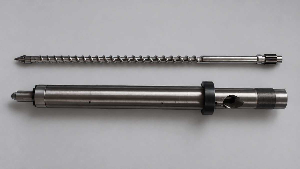
Imagine a syringe. You pull back the plunger, filling the barrel with liquid, then push it forward to dispense a measured dose. An injection molding barrel works the same way. The screw retracts during recovery, metering molten resin in front of it. Then it drives forward, injecting that dose — the shot — into the mold cavity. Shot size is simply how much plastic the machine pushes into the mold per cycle.
For project managers, buyers, and anyone quoting a new tool, the injection molding shot size is the first checkpoint for matching a mold to a machine. Get it right, and you set the foundation for stable production. Get it wrong, and you face a cascade of quality and cost headaches that no amount of process tweaking can fix.
Why Shot Size Matters for Part Quality and Cost
Calculating shot size incorrectly — or skipping the calculation altogether — triggers a predictable chain of failures. When the shot is too small for the cavity, the mold starves. You get short shots, sink marks, and incomplete features. When the barrel is far too large for the shot, resin sits in the heated barrel cycle after cycle. That extended residence time cooks the material, leading to thermal degradation, discoloration, black specks, and weakened mechanical properties. Overpacking the barrel in the other direction compromises melt homogeneity and leaves too little cushion for proper pack-and-hold pressure, producing flash and inconsistent part weights.
An undersized shot starves the cavity; an oversized barrel degrades the resin before it ever reaches the mold.
The financial consequences compound quickly. Degraded resin means scrap, purging downtime, and potential customer rejects. A machine that is too small for the mold forces an expensive rematch mid-production. A machine that is too large burns more energy per cycle and ties up capacity that could serve smaller jobs. As veteran processor John Bozzelli has noted, discovering a barrel-capacity mismatch after a machine is ordered or a schedule is set is never welcome news — and the fix always costs more than doing the homework upfront.
This guide walks you through every step of a proper injection molding machine shot size calculation — from the barrel-capacity formula and material correction factors to runner-system impact, the barrel utilization window, two complete worked examples, and a final machine-verification checklist. The goal is a single, end-to-end reference you can bookmark and revisit whenever a new mold needs a machine or a new machine needs validation.
Every step hinges on one detail that most quick-reference guides gloss over: the numbers on your machine spec sheet are denominated in GPPS, and the resin you run is not polystyrene. Bridging that gap requires understanding how barrel capacity is derived in the first place.
From Machine Specifications to Barrel Capacity
Every injection molding shot size calculation starts in the same place: the machine specification sheet. Whether you are evaluating a press already on your floor or comparing models from a manufacturer's catalog, three numbers form the foundation of the entire calculation. Miss one, misread the units, or confuse rated capacity with actual capacity for your resin, and every downstream number inherits the error.
The three values you need are screw diameter, maximum injection stroke, and rated shot capacity. Let's look at where they appear, what they mean, and how they connect to one another through a straightforward geometric formula.
Reading a Machine Data Sheet for Shot Size Inputs
Open any injection molding machine spec sheet and you will find an injection unit section — sometimes labeled "Injection Unit Specifications" or simply "Plasticizing Unit." According to Huarong's machine specification guide, this section lists parameters such as screw dimension, shot volume, shot weight, injection pressure, and injection speed. The three entries relevant to the shot size calculation are:
- Screw Diameter (D) — listed in millimeters. This is the outer diameter of the injection screw. It defines the cross-sectional area of the melt channel and, as you will see shortly, drives barrel capacity quadratically.
- Maximum Injection Stroke (L) — also in millimeters. This is the farthest distance the screw can travel forward during injection. It sets the upper limit on how much melt the barrel can push into the mold in a single shot.
- Rated Shot Capacity — given in grams (g), ounces (oz), or cubic centimeters (cm³). Here is the critical detail: this value is almost always referenced to GPPS (general-purpose polystyrene). A spec sheet that reads "Shot Weight (PS): 226 g" means the barrel can deliver 226 grams of polystyrene at maximum stroke, not 226 grams of whatever resin you plan to run.
You will sometimes see machines offer multiple screw diameter options for the same clamp frame — for example, a 36 mm, 40 mm, and 45 mm screw on a 150-ton press. Each diameter changes the shot capacity significantly, which is why a single machine model can appear multiple times in a catalog with different injection specs.
Here is what a simplified spec sheet comparison looks like across three machine sizes:
| Machine Class | Screw Diameter (mm) | Max Injection Stroke (mm) | Rated Shot Size — GPPS (g) |
|---|---|---|---|
| Small (50-ton) | 28 | 100 | 58 |
| Mid (150-ton) | 40 | 150 | 178 |
| Large (500-ton) | 70 | 200 | 726 |
Notice how the rated shot size jumps dramatically as screw diameter increases. The 70 mm screw does not simply deliver twice as much material as the 40 mm screw — it delivers roughly four times as much. That nonlinear relationship is baked into the geometry of a cylinder, and understanding it is the key to using any shot size calculator with confidence.
How Screw Diameter and Stroke Determine Barrel Capacity
The barrel in front of the screw is, geometrically, a cylinder. The volume of a cylinder is calculated with a formula you may remember from high school math:
Barrel Capacity (cm³) = (π / 4) × D² × L
Where D is the screw diameter and L is the maximum injection stroke, both expressed in centimeters. This gives you the theoretical maximum volume of melt the screw can displace in one forward stroke.
Let's plug in the mid-size machine from the table above. A 40 mm screw (4.0 cm) with a 150 mm stroke (15.0 cm) yields:
(3.1416 / 4) × 4.0² × 15.0 = 0.7854 × 16 × 15 = 188.5 cm³
That 188.5 cm³ is the volumetric barrel capacity at full stroke. To convert it into the GPPS gram rating you see on the spec sheet, multiply by the melt density of polystyrene — roughly 0.945 g/cm³ — giving about 178 g. That matches the rated shot size in the table, confirming that the spec sheet number is simply barrel volume multiplied by GPPS melt density.
Two relationships jump out of this formula and they matter for every shot size calculation in injection molding:
- Screw diameter increases capacity quadratically. Doubling the diameter from 28 mm to 56 mm does not double the capacity — it quadruples it, because the diameter is squared. Even a modest step up from a 36 mm to a 40 mm screw increases cross-sectional area by roughly 23%.
- Stroke increases capacity linearly. Adding 10% more stroke adds exactly 10% more volume. Stroke adjustments give you fine-tuning; diameter changes give you big jumps.
This is why experienced molders pay close attention to available screw diameters when sizing a machine. A slightly larger screw can open up enough capacity to accommodate a bigger mold, while a slightly smaller one can bring utilization into the ideal window for a small part.
One related spec often causes confusion: the L/D ratio (length-to-diameter ratio of the screw). A 40 mm screw with a total flighted length of 880 mm has an L/D of 22:1. This ratio describes the screw's melting and mixing performance — a higher L/D means more residence length for plasticizing, which is important for melt quality. However, L/D does not tell you the shot capacity by itself. Two screws can share the same L/D ratio yet have completely different diameters, stroke lengths, and therefore vastly different shot volumes. As MD Plastics notes, standard L/D ratios run 18:1 to 24:1 and influence how well the screw melts and mixes — but you still need diameter and stroke to calculate how much material the barrel can deliver per cycle.
With barrel capacity in hand — expressed either as a volume in cm³ or as a GPPS-equivalent weight — the next step is converting that number into a capacity that reflects the resin you actually plan to mold. That conversion hinges on a single multiplier most guides skip past too quickly: the material correction factor derived from melt density.

The Shot Size Calculation Formula Explained
You know your barrel capacity in GPPS grams or cubic centimeters. You know the part weight your mold needs to produce. The temptation at this point is to divide one by the other and call it done. Resist that temptation — because the formula linking those two numbers contains a step that, when skipped, introduces errors large enough to derail machine selection entirely.
The shot size in injection molding is not simply "part weight divided by barrel capacity." It is a structured sequence that accounts for every gram the machine must deliver per cycle, adjusts for the physical difference between your resin and the polystyrene baseline the machine was rated against, and then checks whether the resulting number lands in a safe operating zone. Here is that sequence, laid out so you can follow it from raw inputs to a confirmed machine match.
The Shot Size Formula Step by Step
How to calculate shot size in injection molding comes down to five discrete steps. Each one builds on the previous, and skipping any single step compromises the accuracy of everything that follows.
- Determine total part weight. Multiply the weight of a single part by the number of cavities in the mold. If you are running a four-cavity mold and each part weighs 35 g, the total part weight is 140 g. Use the solid (room-temperature) density of your resin multiplied by the part volume from CAD if you do not yet have a physical part to weigh.
- Add runner and sprue weight (cold runner molds only). In a cold runner system, the runner, sprue, and sub-runners solidify every cycle and eject with the parts. This material must be included in the total cycle weight. Runner weight can range from a small fraction to 30% or more of the total shot, especially in multi-cavity tools with long flow paths. For hot runner molds, skip this step — the runner stays molten and is not part of the per-cycle shot. (A later section covers this distinction in detail.)
- Apply the melt-density correction factor. Because your machine's rated capacity is expressed in GPPS, you need to convert your total cycle weight into its GPPS equivalent so the comparison is apples to apples. The correction factor is the ratio of GPPS melt density to your resin's melt density:
Correction Factor = Melt Density of GPPS / Melt Density of Your Resin
Multiply the total cycle weight from Step 2 by this factor to get the GPPS-equivalent shot weight. For example, if you are molding polypropylene with a melt density of about 0.74 g/cm³ and GPPS has a melt density of roughly 0.945 g/cm³, the correction factor is 0.945 / 0.74 = 1.28. A 164 g PP shot becomes 164 × 1.28 = 210 g in GPPS-equivalent terms. That 46-gram jump is invisible if you skip the correction — and it is the difference between a barrel that looks adequate on paper and one that is actually undersized for your job. - Calculate barrel utilization percentage. Divide the corrected (GPPS-equivalent) shot weight by the machine's rated barrel capacity and multiply by 100:
Utilization % = (GPPS-Equivalent Shot Weight / Rated Barrel Capacity) × 100
This percentage tells you how much of the barrel's available volume each cycle consumes. - Confirm the result falls within the recommended utilization window. Industry best practice places the target between roughly 20% and 65% of barrel capacity. Falling below 20% means the resin dwells in the heated barrel for too many cycles, risking thermal degradation. Exceeding 65% compromises melt homogeneity and leaves insufficient cushion for pack-and-hold pressure. If your utilization percentage lands outside this window, the machine is not a good match — regardless of how well the clamp tonnage or platen size fits the mold.
Pulling these steps together, the core formula looks like this:
Required Shot Size (GPPS-equivalent) = (Part Weight × No. of Cavities + Runner Weight + Sprue Weight) × Correction Factor
And the verification check:
Utilization % = Required Shot Size (GPPS-equivalent) / Rated Barrel Capacity (GPPS) × 100
Many experienced molders also add a 10% safety margin to the required shot size before running the utilization check. This buffer accounts for real-world variables like check-ring leakage and minor shot-to-shot variation. As John Bozzelli recommends, building that safety factor into the calculation upfront prevents unpleasant surprises once the mold is hung and the machine is cycling.
Understanding the Material Correction Factor
Of the five steps above, Step 3 is where most calculations go wrong. The correction factor exists for a simple physical reason: different polymers occupy different volumes per gram when molten. A barrel rated at 226 g of GPPS can hold 226 grams of polystyrene melt — but polystyrene melt has a specific density. Swap in a resin with a lower melt density, like polypropylene or HDPE, and each gram of that resin takes up more space inside the barrel. The barrel's volume has not changed, but the weight of material it can hold has dropped.
Think of it this way. Imagine two buckets of identical size. Fill one with wet sand and the other with dry popcorn. Both buckets are full to the brim — same volume — but they weigh very different amounts because the materials have different densities. Your injection barrel works exactly the same way. As Suhas Kulkarni illustrates, replacing polystyrene with a glass-filled PBT (density 1.53 g/cm³) increases the barrel's weight capacity, while replacing it with a lower-density polyolefin decreases it — even though the barrel itself is physically unchanged.
A critical nuance here: you must use melt densities, not room-temperature solid densities. When polymer molecules are heated to processing temperature, they spread apart, and density drops. The magnitude of that drop varies by resin type. Polystyrene's solid density is about 1.04 g/cm³, but its melt density falls to roughly 0.945 g/cm³. Polypropylene drops from around 0.90 g/cm³ solid to approximately 0.74 g/cm³ molten. Using solid densities instead of melt densities in the correction factor underestimates the volume your resin actually occupies inside the barrel, and the whole calculation drifts optimistic — telling you the machine has more room than it really does.
Processors sometimes estimate melt density by multiplying the solid density by a factor of 0.70 to 0.80, a rule of thumb noted in Plastics Technology's coverage of density calculations. That range gives a reasonable starting point, but the precise value depends on melt temperature and back pressure — both of which shift from application to application. For tighter accuracy, you can calculate melt density empirically from a known process: divide the shot weight by the volume the screw displaced (shot size position minus cushion, converted to volume using the barrel's cross-sectional area). This method, detailed in Kulkarni's work, yields a number specific to your actual processing conditions rather than a textbook average.
Skipping the material correction factor is the single most common error in shot size calculation — it can throw your estimate off by 20% or more depending on the resin.
Consider the real-world impact. A molder scheduling a PP job on a machine rated at 226 g GPPS might assume 164 g of PP fits comfortably — that is only 73% of 226 g, which seems fine at a glance. Apply the melt-density correction, though, and the GPPS-equivalent jumps to 210 g. Add Bozzelli's recommended 10% safety factor and you reach 231 g — already beyond the barrel's 226 g rating. What looked like a comfortable fit is actually a machine that cannot deliver the shot. This is precisely the scenario custom molders encounter when they skip the density offset and discover process instability only after the mold is running.
The correction factor is not a single fixed number per resin, either. It shifts with filler content, specific grade formulation, and processing temperature. A 30% glass-filled nylon behaves differently from a neat nylon. A PP copolymer processed at 230 °C has a different melt density than the same grade processed at 260 °C. The most reliable approach is to request melt-density data from your resin supplier for the specific grade and temperature range you plan to use, then calculate the correction factor from that data.
So far, the correction factors discussed have been described conceptually — ratios, ranges, and a single PP example. Applying this step confidently across a range of resins demands a reference table mapping common polymers to their approximate melt densities and correction factors, a resource that most quick-reference guides fail to provide.
Melt Density Corrections for Real-World Resins
The previous section described the correction factor as a ratio of melt densities — a clean concept in the abstract. The practical question is: what is shot size in injection molding terms for your specific resin? Answering that requires actual numbers, not just a formula. Polypropylene, polycarbonate, nylon, acetal, and every other common polymer each displace a different volume per gram when molten, and those differences are large enough to shift your machine selection in either direction.
The table below fills a gap that most quick-reference guides leave open. It maps twelve of the most frequently injection-molded resins to their approximate melt densities and the correction factors you need for converting a GPPS-rated barrel capacity into a meaningful number for your application.
Why GPPS-Rated Capacity Does Not Equal Actual Capacity
GPPS became the industry benchmarking standard for a practical reason: it melts predictably, flows consistently, and has well-documented thermal behavior. When machine builders need a single resin to stamp onto a spec sheet, polystyrene is the obvious choice. The problem is that almost nobody molds GPPS in production volumes compared to the universe of PP, PE, nylons, polycarbonate, ABS, and engineering resins that fill real-world factories.
Each of those resins has a different melt density — the mass per unit volume of the polymer in its molten state at processing temperature. A machine rated at 200 g GPPS has a fixed barrel volume. Pour in a resin with a lower melt density than polystyrene, and fewer grams fit in that same volume. Pour in a denser melt, and more grams fit. The barrel has not changed; only the weight it can deliver per stroke has shifted.
Consider two extremes from the Stelray density reference tables. Polypropylene has a melt density of roughly 0.70 g/cm³, while acetal (POM) sits around 1.17 g/cm³. On that same 200-g-GPPS machine:
- PP capacity: 200 × (0.70 / 0.97) = approximately 144 g
- POM capacity: 200 × (1.17 / 0.97) = approximately 241 g
That is a 97-gram swing — nearly half the machine's rated capacity — driven entirely by the resin in the hopper. Ignore melt density, and you could schedule a polypropylene job on a machine that physically cannot deliver the shot, or tie up an oversized machine for an acetal part that could run on a smaller press.
Melt Density Correction Factors for Common Resins
The correction factor used in the shot size formula (established in the previous section) follows this relationship:
Correction Factor = GPPS Melt Density / Resin Melt Density
You multiply your total cycle weight by this factor to convert it into a GPPS-equivalent value that you can compare directly against the machine's rated capacity. A correction factor above 1.00 means the resin is lighter than GPPS in the melt — it occupies more barrel volume per gram, so the barrel effectively holds fewer grams. A factor below 1.00 means the resin is denser than GPPS in the melt, and the barrel can deliver more grams per stroke.
The table below uses a GPPS melt density baseline of 0.97 g/cm³, consistent with published resin density data from Stelray. All values are approximate and representative of unfilled grades at typical processing temperatures.
| Resin | Typical Melt Density (g/cm³) | Correction Factor vs. GPPS |
|---|---|---|
| GPPS (General-Purpose Polystyrene) | 0.97 | 1.00 (baseline) |
| ABS (Injection Grade) | 0.97 | 1.00 |
| PA6 (Nylon 6) | 0.97 | 1.00 |
| PA66 (Nylon 6/6) | 0.97 | 1.00 |
| PMMA (Acrylic, General Purpose) | 1.04 | 0.93 |
| PC (Polycarbonate) | 1.02 | 0.95 |
| PBT (Polyester) | 1.11 | 0.87 |
| POM (Acetal) | 1.17 | 0.83 |
| TPU (Polyurethane Elastomer) | 1.13 | 0.86 |
| LDPE (Low-Density Polyethylene) | 0.76 | 1.28 |
| HDPE (High-Density Polyethylene) | 0.72 | 1.35 |
| PP (Polypropylene) | 0.70 | 1.39 |
A few patterns stand out immediately. The polyolefins — PP, HDPE, and LDPE — all carry correction factors well above 1.00. These are the resins where skipping the density adjustment hurts the most. A molder running polypropylene without the correction underestimates the GPPS-equivalent shot by nearly 40%. That is not a rounding error; it is a miscalculation that can push barrel utilization beyond the safe window or result in a machine that simply cannot fill the mold.
On the other side of the table, engineering resins like POM, PBT, and TPU have melt densities higher than GPPS. Their correction factors fall below 1.00, meaning the barrel actually delivers more grams per stroke than the GPPS rating suggests. For these materials, the risk flips: you might select a machine larger than necessary, wasting energy and increasing residence time without realizing the smaller press down the aisle could handle the job.
ABS and the nylons (PA6, PA66) land right at the GPPS baseline — a melt density near 0.97 g/cm³ — so their correction factors hover around 1.00. For these resins, the GPPS rating on the spec sheet is a reasonable proxy for actual capacity. That coincidence, however, can breed a false sense of security. Molders who happen to run mostly ABS or nylon may never encounter a density-driven mismatch and then get blindsided the first time they quote a polypropylene or HDPE project on the same equipment.
Keep in mind that these values represent unfilled, commodity grades at mid-range processing temperatures. Real-world conditions shift the numbers in several ways:
- Fillers and reinforcements increase melt density. A 30% glass-filled nylon has a significantly higher density than neat nylon, which lowers the correction factor and increases the effective gram capacity of the barrel.
- Processing temperature affects melt density inversely. Running a resin at the high end of its recommended window lowers melt density slightly compared to the low end, because the polymer chains spread farther apart at higher thermal energy.
- Grade-to-grade variation exists even within the same polymer family. A PP homopolymer, a PP random copolymer, and a PP impact copolymer each have subtly different melt densities.
For custom-size two-shot injection molding applications or any project where tight weight tolerance matters, relying on table averages introduces unnecessary risk. The most reliable path is to request melt-density data directly from your resin supplier for the specific grade and processing temperature you plan to use. Many material data sheets now include melt density at one or more reference temperatures — if yours does not, ask for it. The correction factor you calculate from supplier-specific data will always be more accurate than a generic table value.
With the correction factor applied, your shot size estimate finally reflects the actual resin going into the barrel. The next variable that determines whether that number is complete or incomplete is the runner system sitting between the barrel and the cavity — because whether those channels are cold or hot changes which grams count toward each cycle's shot.

How Runner Systems Determine Injection Mold Shot Size
Your melt-density correction factor is dialed in. Your part weights are accurate. Yet the number you plug into the shot size formula can still be fundamentally wrong if you miscategorize the material that travels between the barrel and the cavity. The runner system — the network of channels, sprues, and gates that delivers melt from the nozzle to each cavity — either adds a significant chunk of plastic to every cycle or contributes almost nothing, depending on whether those channels run cold or hot.
This distinction changes the definition of shot size in injection molding for a given mold. Overlook it, and you will either oversize the machine for a hot runner tool or undersize it for a cold runner tool. Both mistakes carry real cost.
Cold Runner Molds and Full-System Shot Weight
In a cold runner system, the sprue, primary runner, sub-runners, and gates are all unheated channels cut into the mold plates. Molten plastic flows through them on its way to the cavities, but once the cooling cycle finishes, every bit of that channel material solidifies right alongside the parts. The mold opens, and the runner system ejects as a solid tree of plastic — still physically attached to the parts or separated by shearing at the gate.
Because that solidified runner ejects every single cycle, it must be counted in the total shot weight. There is no way around it: the machine has to push enough melt to fill the parts and the entire runner network in one forward stroke of the screw.
How much weight does the runner add? It depends on the mold layout. A two-cavity mold with a short, balanced runner might add 10-15% to the total cycle weight. A 16-cavity mold with long flow paths and thick primary runners can push that figure to 30% or higher. Imagine running a four-cavity mold where each part weighs 25 g — the parts total 100 g. If the cold runner tree weighs another 30 g, the machine must deliver 130 g every cycle. Drop that runner weight from the calculation, and you underestimate the required shot by 23%.
Runner thickness matters too. As SIMTEC's engineering team notes, cold runner dimensions must be larger than the part wall thickness to ensure the melt packs into the cavity before the runner freezes off. Thicker runners mean heavier runners, which in turn inflate the shot size your machine must handle. For anyone trying to determine shot size for injection molding on a cold runner tool, ignoring the runner tree is like calculating the fuel for a road trip but forgetting to include the drive back.
Hot Runner Molds and Cavity-Only Calculations
Hot runner molds flip the equation. A heated manifold system keeps the entire runner channel — from the machine nozzle through the manifold and drops down to the gate — at or above the resin's melt temperature throughout the cycle. The plastic inside those channels never solidifies. When the mold opens, only the molded parts (and a tiny gate vestige at each drop) eject. The runner material stays molten inside the manifold, ready to be pushed forward on the next shot.
This means the per-cycle shot weight for a hot runner mold is dramatically simpler:
Shot Weight = Part Weight × Number of Cavities + Gate Vestige (negligible)
No sprue weight. No runner tree. No sub-runner branches. For that same four-cavity, 25-g-part example, the hot runner shot is essentially 100 g — not 130 g. That 30-gram reduction can shift barrel utilization by 10 percentage points or more, potentially allowing you to run the job on a smaller, less expensive machine.
There is a nuance worth flagging, though. The molten plastic sitting inside the hot runner manifold does not vanish — it still exists inside the mold, occupying volume and absorbing heat cycle after cycle. While it is not part of the per-cycle shot weight, it absolutely contributes to residence time. A large manifold holding a significant volume of melt means some portion of that material dwells at processing temperature for extended periods, which matters for thermally sensitive resins. When you verify machine suitability later in the process (covered in a subsequent section), residence time calculations must account for the manifold volume even though the shot size calculation does not.
Gate geometry — whether the mold uses a hot-tip, valve gate, or edge gate — also deserves a quick note. Different gate styles affect injection pressure requirements and the aesthetic quality of the gate mark on the finished part. Valve gates, for instance, produce a cleaner surface finish and are common in medical device molding, while hot tips may leave a small remnant. These design choices influence processing parameters and cycle time, but they do not meaningfully change the weight of material the machine must inject per cycle. Pressure drop through a restrictive gate may require higher injection pressure, yet the total mass delivered remains the same.
Side-by-Side: What Counts Toward Shot Size
The table below lays out exactly which weight components enter the shot size calculation for each runner type. Use it as a quick-reference checklist when you are determining injection mold shot size for a new project.
| Calculation Component | Cold Runner | Hot Runner |
|---|---|---|
| Part Weight × Number of Cavities | Included | Included |
| Sprue Weight | Included | Excluded (stays molten) |
| Primary Runner Weight | Included | Excluded (stays molten) |
| Sub-Runner / Branch Weight | Included | Excluded (stays molten) |
| Gate Vestige | Included (shear remnant) | Minimal (tip or valve mark) |
| Manifold Melt Volume | N/A | Not in shot weight, but affects residence time |
| Melt-Density Correction Factor | Applied | Applied |
Notice that the melt-density correction factor applies in both scenarios. Whether the runner is cold or hot, the machine's barrel is still rated in GPPS, and the resin you are processing still has its own melt density. The runner type determines what you are correcting; the correction factor determines how much adjustment is needed relative to the machine's published capacity.
For molders evaluating a mold conversion — say, retrofitting a cold runner tool with a hot runner system — this table makes the downstream impact tangible. Eliminating the runner weight from the per-cycle shot can reduce barrel utilization enough to open the door to a smaller machine, shorten cycle times (no runner to cool), and cut material waste. The tradeoff is higher upfront mold cost and added maintenance for the manifold and heater system, a balance Aptyx's engineering team frames as a decision driven by production volume, part specification, and budget goals.
With the runner system's contribution properly categorized, every variable in the shot size formula is accounted for: part weight, cavity count, runner weight (or lack thereof), and the melt-density correction. The remaining question is whether the resulting number actually fits the machine — and that answer lives inside the barrel utilization window, where too little and too much each carry their own set of consequences.
The Barrel Utilization Rule and Why the Ideal Shot Size Percentage Matters
Every guide on injection molding shot size calculation mentions the 20-65% barrel utilization window. Most leave it at that — a pair of numbers with no explanation of where they come from, what breaks when you cross them, or what to do if your calculation lands outside. That is a problem, because a number without context is just trivia. Understanding why those boundaries exist turns them into actionable engineering limits you can defend during machine selection, troubleshoot against during production, and push back on when someone suggests ignoring them.
Think of barrel utilization as a comfort zone for molten plastic. Too little material cycling through the barrel, and the resin overcooks. Too much, and the screw cannot do its job properly. Both extremes produce the same frustrating outcome: inconsistent shot size in injection molding, unpredictable part weights, and quality defects that resist process adjustment. The difference is in the failure mechanism — and knowing which one you are fighting determines the fix.
Why the Lower Bound Exists — Residence Time and Degradation
Imagine a heated barrel that can hold 500 grams of GPPS-equivalent melt, but the mold only requires a 50-gram shot. That is 10% utilization — well below the 20% floor. What happens to the other 450 grams of molten plastic sitting in the barrel?
It waits. Cycle after cycle, the bulk of the melt sits at processing temperature while only a small fraction gets pushed into the mold and replaced with fresh material. The number of shots' worth of material sitting in the barrel — sometimes called the barrel inventory — climbs dramatically as utilization drops. At 10% utilization, roughly ten full shots' worth of resin occupy the barrel at any given moment. Multiply that by the cycle time, and you get the residence time: the total duration any given pellet spends in the heated barrel from the moment it enters to the moment it exits through the nozzle.
Extended residence time is not a theoretical concern — it actively degrades the polymer. Here is how the damage unfolds:
- Thermal degradation: Polymer chains break down when exposed to heat beyond their stability window. The barrel temperature itself may be within spec, but the duration of exposure pushes the material past its limits. Degraded chains mean reduced molecular weight, weaker mechanical properties, and brittleness in the finished part.
- Discoloration and black specks: Overcooked resin yellows, darkens, or produces carbonized particles — black specks that embed themselves in otherwise good parts. These defects are cosmetically unacceptable in most applications and structurally suspect in all of them.
- Outgassing and odor: Some polymers release volatile byproducts as they degrade. These gases can cause splay, bubbles, or surface defects on the molded part, and they accelerate corrosion inside the barrel and mold.
- Loss of process control: Degraded melt behaves differently from fresh melt. Viscosity shifts unpredictably, fill patterns change, and shot-to-shot consistency erodes. You end up chasing a process that refuses to stabilize because the material itself is no longer uniform.
A barrel that is far too large for the shot essentially cooks the material. As Basilius engineering explains, having too small of a shot size relative to barrel capacity causes longer residence times, material degradation, quality issues, and poor process control. The 20% lower bound exists precisely to cap residence time at a level most commodity and engineering resins can tolerate without significant property loss.
The sensitivity varies by resin. PVC, POM, and certain bio-based polymers degrade aggressively at elevated temperatures and demand tighter residence-time limits. Polyolefins like PP and PE are more forgiving, but even they will yellow and lose impact strength if they sit in a barrel long enough. When you are molding a thermally sensitive material and your utilization calculation dips below 20%, treat it as a hard stop — not a soft guideline.
Why the Upper Bound Exists — Cushion and Melt Homogeneity
The upper boundary of 65% is less about time and more about space — specifically, the space the screw needs to do two critical jobs during every cycle: maintaining a cushion and ensuring uniform melt quality.
Cushion is the small pad of melt that remains in front of the screw after injection is complete. It acts as a hydraulic buffer during the pack-and-hold phase, allowing the machine to transmit holding pressure into the cavity to compensate for volumetric shrinkage as the part cools. Without adequate cushion, the screw bottoms out against the barrel end cap, holding pressure drops to zero, and the cavity is left to shrink freely. The result? Sink marks, voids, dimensional variation, and inconsistent part weight — the textbook symptoms of injection molding inconsistent shot size problems.
When barrel utilization exceeds 65%, the screw is already near the end of its stroke after delivering the shot. There is physically little room left for a stable cushion. Even minor shot-to-shot variation — from check-ring leakage, slight plastication differences, or temperature fluctuations — can push the cushion to zero on some cycles and leave a surplus on others. That inconsistency ripples directly into part weight and dimensional scatter.
Melt homogeneity is the second casualty. The screw does not just push plastic forward — it melts, mixes, and homogenizes the resin as it rotates during recovery. A larger shot demands more screw retraction, which means the screw has less effective mixing length available during plastication. The melt that reaches the front of the barrel may contain unmelted pellets, temperature gradients, or poorly dispersed additives. You can sometimes compensate with higher back pressure or slower screw speed, but those adjustments increase cycle time and may introduce other issues like shear heating.
Rosti's processing guidance frames the upper limit slightly more conservatively, noting that large shot sizes exceeding 50% of barrel capacity can lead to poor melt uniformity and extended screw recovery times. Whether you draw the line at 50% or 65% depends on the resin, the screw design, and how much process margin your quality requirements demand. For thermally sensitive or high-performance resins, erring toward the lower end of that range is prudent. For robust commodity resins with wide processing windows, pushing closer to 65% is more defensible — but exceeding it is rarely wise.
When Barrel Utilization Falls Outside the Window
So your injection molding shot size calculation returned a utilization of 12%. Or 78%. The number is outside the safe zone. What are your options?
The most straightforward corrective action is selecting a machine with a different screw diameter. Many press manufacturers offer two or three screw-diameter options for the same clamp frame. Stepping down from a 45 mm screw to a 36 mm screw on a 150-ton machine, for example, reduces barrel capacity by roughly 36% — enough to bring a low-utilization job back into range without changing the clamp tonnage or press footprint. Stepping up works the same way in reverse for an oversized shot.
Sometimes, though, the clamp tonnage requirement locks you into a specific machine. A mold with a large projected area needs every bit of a 500-ton press, but the part itself is small and the shot only uses 15% of that machine's barrel. In these cases, consider the following options:
- Evaluate whether the plasticizing unit can be resized. Some machine platforms allow the injection unit to be swapped or reconfigured with a smaller screw and barrel assembly that fits the same drive system. This reduces barrel volume without changing the clamp side of the equation.
- Adjust the mold design. Adding cavities (if part demand supports it) increases the per-cycle shot and raises utilization. Conversely, for an oversized shot, reducing cavity count or switching from a cold runner to a hot runner (eliminating runner weight) can bring the number down.
- Review cycle time. A shorter cycle time reduces residence time even at low utilization, partially offsetting the risk of degradation. This is a mitigation, not a cure — it helps with borderline cases but cannot rescue a gross mismatch.
- Inspect and replace worn plasticizing components. This is where hardware condition enters the equation. A worn check ring that does not seal properly allows melt to flow backward past the screw during injection, reducing the effective shot the machine delivers. A scored barrel with increased clearance between the screw flight OD and the barrel ID compounds the problem — material slippage increases, compression efficiency drops, and dead zones develop, all of which erode volumetric consistency. Even if your calculation says 30% utilization, a worn barrel and check ring might mean you are effectively operating at 22% — right at the edge.
For molders who have confirmed that the plasticizing unit itself is the weak link — whether because of wear, a mismatch from repurposing the machine for a different resin, or a screw geometry that was never optimized for the current application — replacing the screw and barrel with components tailored to the job is one of the most direct fixes available. NANHAIYA's custom injection molding screw barrels are manufactured around the specific machine platform, resin characteristics, and shot requirements of each application, with a technical review that evaluates screw geometry, wear resistance, melting efficiency, mixing performance, and material-retention behavior. This kind of tailored approach is especially relevant when the calculation reveals that utilization is borderline and the existing hardware introduces enough variability to push it outside the window.
Regardless of the corrective path you choose, the key takeaway is that barrel utilization is not a suggestion — it is a physical constraint rooted in polymer science and machine mechanics. An injection molding machine does not care whether the number on your spreadsheet says 25%. If the barrel is worn, the check ring leaks, or the screw geometry mismatches the resin, your effective utilization may be very different from your calculated utilization. Verifying the hardware matches the math is what separates a reliable process from one that drifts.
All of the principles discussed so far — barrel capacity, melt-density correction, runner-system impact, and utilization boundaries — come together most clearly when you walk through a complete calculation from start to finish. Seeing the numbers interact across a real scenario reveals details that formulas alone cannot convey, especially when you compare a cold runner layout against a hot runner layout on the same part.

Two Complete Worked Examples You Can Follow
Formulas are useful. Formulas with numbers running through them are unforgettable. The two scenarios below put every concept from the previous sections — part weight, runner contribution, melt-density correction, safety margin, and barrel utilization — into motion so you can see exactly how each variable shifts the final answer. One example uses a cold runner multi-cavity mold running polypropylene; the other uses a hot runner single-cavity mold running polycarbonate. The contrast between the two reveals just how dramatically runner type and resin choice reshape the injection molding machine shot size your application demands.
Worked Example — Cold Runner Multi-Cavity Mold
Picture a four-cavity cold runner mold producing small PP housings. Here is how the calculation unfolds, step by step:
- Determine total part weight. Each cavity produces a part weighing 30 g. Four cavities yield a total part weight of 4 × 30 = 120 g.
- Add runner and sprue weight. The cold runner tree — sprue, primary runner, and four sub-runner branches — weighs 36 g. This material solidifies and ejects every cycle, so it must be included. Total cycle weight: 120 + 36 = 156 g.
- Apply the melt-density correction factor. From the correction table established earlier, polypropylene carries a factor of 1.39 (based on a GPPS melt density of 0.97 g/cm³ divided by PP's 0.70 g/cm³). GPPS-equivalent shot weight: 156 × 1.39 = 217 g.
- Add a 10% safety margin. This buffer accounts for check-ring leakage and shot-to-shot variation. Adjusted shot: 217 × 1.10 = 239 g (GPPS equivalent).
- Identify a candidate machine. A 250-ton press with a 50 mm screw is rated at 400 g GPPS barrel capacity.
- Calculate barrel utilization. Utilization = 239 / 400 × 100 = 59.8%.
- Confirm the result. 59.8% falls within the 20–65% window. The machine can deliver the shot with adequate cushion and acceptable residence time. This press is a viable match for the job.
Notice the correction factor's impact. Without it, a molder might compare 156 g of PP directly to the 400 g GPPS rating and conclude utilization is only 39%. The actual figure — nearly 60% — tells a very different story. That gap is the entire reason melt density cannot be skipped.
Worked Example — Hot Runner Single-Cavity Mold
Imagine a single-cavity hot runner mold producing a PC (polycarbonate) structural bracket. The runner stays molten inside the manifold, so the per-cycle calculation simplifies considerably:
- Determine total part weight. One cavity, one part weighing 82 g. Total part weight: 82 g.
- Assess runner contribution. The hot runner manifold keeps the melt channel heated — no solidified runner ejects. Runner weight added to the shot: 0 g. Total cycle weight: 82 g.
- Apply the melt-density correction factor. Polycarbonate has a correction factor of 0.95 (GPPS melt density of 0.97 g/cm³ divided by PC's 1.02 g/cm³). GPPS-equivalent shot weight: 82 × 0.95 = 78 g.
- Add a 10% safety margin. Adjusted shot: 78 × 1.10 = 86 g (GPPS equivalent).
- Test against the same 250-ton, 400 g machine. Utilization = 86 / 400 × 100 = 21.5%. That scrapes the bottom of the acceptable range, and residence time on a thermally sensitive resin like PC becomes a real concern at this level.
- Evaluate a smaller machine. A 150-ton press with a 40 mm screw rated at 178 g GPPS is a better candidate. Utilization = 86 / 178 × 100 = 48.3%.
- Confirm the result. 48.3% sits comfortably in the middle of the utilization window — plenty of room for cushion, good melt homogeneity, and manageable residence time. The smaller machine is the right choice, assuming clamp tonnage and platen size accommodate the mold.
Two things stand out in this example. First, the hot runner eliminated the entire runner weight from the cycle, shrinking the raw shot from what would have been roughly 110–120 g (had a cold runner been used) down to 82 g. Second, polycarbonate's correction factor actually reduced the GPPS-equivalent number because PC melt is denser than polystyrene melt — the barrel effectively holds more grams of PC per stroke. Together, these factors opened the door to a press nearly half the injection-unit size of the cold runner scenario's machine.
Side-by-Side Comparison
The table below summarizes both examples so you can see the injection molding part volume to shot size relationship at a glance. Every row traces a different variable, and the final utilization percentages highlight how runner type and resin selection compound to reshape machine requirements.
| Parameter | Example 1 — Cold Runner PP | Example 2 — Hot Runner PC |
|---|---|---|
| Part Weight per Cavity | 30 g | 82 g |
| Number of Cavities | 4 | 1 |
| Total Part Weight | 120 g | 82 g |
| Runner + Sprue Weight | 36 g | 0 g (hot runner) |
| Total Cycle Weight | 156 g | 82 g |
| Resin Correction Factor | 1.39 (PP) | 0.95 (PC) |
| GPPS-Equivalent Shot | 217 g | 78 g |
| With 10% Safety Factor | 239 g | 86 g |
| Candidate Barrel Capacity (GPPS) | 400 g (250-ton press) | 178 g (150-ton press) |
| Barrel Utilization | 59.8% | 48.3% |
| Within 20–65% Window? | Yes | Yes |
The injection molding machine shot size by tonnage relationship is visible here, too. The PP cold runner job requires a 250-ton class machine not because of clamp force alone, but because the combined effect of four cavities, a full runner tree, and a high correction factor demands a larger barrel. The PC hot runner job, despite using a heavier individual part, fits a 150-ton machine comfortably because no runner weight inflates the shot and the resin's higher melt density works in the barrel's favor.
Running through these numbers yourself — substituting your own part weights, cavity counts, and resin grades — is the fastest way to internalize the calculation. And if your parts exist only as CAD models at this stage, the question becomes how to extract reliable weight estimates from digital geometry before a single pellet has been melted.
Translating CAD Data Into Injection Molding Shot Size Inputs
Every worked example so far started with a known part weight — 30 g, 82 g — as though that number simply appeared. In practice, most projects reach the shot sizing stage long before a physical part exists to place on a scale. The part lives inside a CAD file, and pulling a reliable weight estimate from that digital geometry is the real starting point of the injection molding shot size formula. Get this step wrong, and every calculation downstream — correction factor, utilization, machine selection — inherits the error.
The gap between a 3D model on screen and the grams-per-cycle number on a process sheet is smaller than it seems, but it involves a few conceptual steps that trip up even experienced engineers when they move too quickly.
Extracting Part Volume from CAD Software
Every major CAD platform includes a mass-properties or volume-analysis tool. In SolidWorks, you will find it under Evaluate > Mass Properties. CATIA uses Measure Inertia. Siemens NX, Creo, and Fusion 360 each have their own equivalent. The output you need is the part volume, typically reported in cubic millimeters (mm³) or cubic centimeters (cm³). If the software reports mm³, divide by 1,000 to convert to cm³.
One critical requirement: run the analysis on the net molded geometry — the final part model complete with draft angles, fillets, ribs, bosses, and every feature the mold will actually produce. A simplified bounding-box approximation or an early-stage concept model without draft and radii will overestimate or underestimate the volume, sometimes by 5-10% depending on part complexity. As Huashuo Molding's engineering guide notes, single-part volume is typically derived directly from the CAD model's volume output, and that output must reflect the geometry the mold will form — not an idealized or pre-draft version.
For multi-cavity molds, total part volume is straightforward: multiply the single-part volume by the number of cavities. But make sure each cavity produces the same part geometry. If cavities are family-style (different parts in the same mold), sum each unique volume individually.
Converting Volume to Weight Using Solid and Melt Density
Here is where a common confusion surfaces, and it is worth slowing down to untangle it.
You have a part volume in cm³ from CAD. You want a part weight in grams. The conversion is simple multiplication:
Part Weight (g) = Part Volume (cm³) × Solid Density of Resin (g/cm³)
You use solid density — the room-temperature density listed on the resin data sheet — because part weight describes what the finished, cooled part will weigh when it lands on a scale. A polypropylene part with a volume of 33.3 cm³ and a solid density of 0.90 g/cm³ weighs about 30 g. That is the number you carry into the injection molding shot size formula as "part weight per cavity."
The confusion creeps in when it is time to compare that part weight against the machine's barrel capacity. The barrel does not deliver solid plastic — it delivers molten plastic, which has a lower density and therefore occupies more volume per gram. This is exactly why the melt-density correction factor exists: it bridges the gap between the weight of the solid part you want and the volume of molten resin the barrel must displace to deliver that weight.
Think of it as two separate questions:
- "How heavy is my part?" — Answer using solid density. This gives you shot weight in real grams.
- "Can my machine deliver that weight as a melt?" — Answer using the melt-density correction factor. This converts your real-gram shot weight into a GPPS-equivalent number you can compare against the machine's rated capacity.
Mixing up the two densities — applying melt density to estimate part weight, or solid density to gauge barrel capacity — is a quiet error that skews the entire calculation. As Suhas Kulkarni emphasizes in Plastics Technology, to determine what the part will weigh, the designer multiplies the volume of the part by the density of the material from which it will be molded — and that density is the solid density. The melt density enters the picture only when you are sizing the barrel and evaluating whether the machine can deliver the shot.
For injection molding shot size polypropylene projects, this distinction matters more than usual. PP's solid density (~0.90 g/cm³) and melt density (~0.70 g/cm³) diverge by over 22%. Using solid density in place of melt density when checking barrel capacity makes the machine look like it has more room than it actually does — a mistake that compounds with every cavity added to the mold.
Accounting for Shrinkage in the Calculation
There is one more layer between the CAD model and the actual injection molding size shot the machine must deliver: shrinkage. Plastic parts shrink as they cool from melt temperature to room temperature. To compensate, mold cavities are cut larger than the final part dimensions — a practice tooling engineers call cutting "steel-safe." The cavity volume the machine must fill on each cycle is therefore bigger than the finished-part volume your CAD model reports.
How much bigger depends on the resin. ICOMold's shrinkage guide notes that typical shrink rates range from 0.001 in/in to 0.020 in/in, with the average hovering around 0.006 in/in. When calculating shrinkage compensation, the tooling engineer scales the mold dimensions by a factor of 1.00X, where X is the material's shrinkage rate. That scaling increases the cavity volume proportionally.
Two broad resin categories behave very differently here:
- Amorphous resins (ABS, PC, PMMA, polystyrene) typically shrink in the range of 0.004–0.007 in/in. Their molecular chains do not reorganize into crystalline structures during cooling, so dimensional change is relatively modest and uniform.
- Semi-crystalline resins (PP, PE, PA6, PA66, POM, PBT) shrink significantly more — often 0.010–0.020 in/in — because their chains pack tightly into ordered crystalline regions as the melt cools. Higher crystallinity means greater volumetric contraction.
For the shot size calculation, this means the cavity volume (and therefore the melt volume the machine must deliver) is larger than the CAD part volume by a factor related to the shrinkage rate. A polypropylene part with a nominal CAD volume of 33.3 cm³ might require a cavity volume of roughly 34.3 cm³ after shrinkage compensation — an increase of about 3%. That may sound trivial on a single cavity, but multiply it across an eight-cavity mold and the cumulative difference adds measurable grams to the required shot.
There is also an asymmetric shrinkage consideration for filled resins. Glass-fiber-reinforced nylons, for instance, shrink less in the direction of fiber alignment (flow direction) than in the transverse direction. As ICOMold's engineering team explains, this makes round features become elliptical and complicates cavity geometry. While this asymmetry primarily affects dimensional tolerances rather than total shot volume, it reinforces the importance of using cavity volume — not simplified CAD volume — as the true input for your calculation.
The most accurate approach is to ask your tooling supplier for the cavity volume after shrinkage compensation has been applied. If that number is not yet available (perhaps the mold is still being quoted), apply the material's published shrinkage rate to the CAD part volume as a volumetric scale factor: multiply the CAD volume by (1 + shrinkage rate)³ for a three-dimensional approximation. The result gives you a closer estimate of the melt volume the machine actually needs to push into the mold each cycle.
With a reliable part weight derived from CAD geometry, a clear understanding of which density applies where, and shrinkage accounted for, the shot size number feeding into your formula is as accurate as it can be before steel is cut. The final step is zooming out from the shot itself to verify that the machine — as a complete system — can support the process, checking not just barrel capacity but residence time, cushion, clamp tonnage, and the condition of the plasticizing hardware.

Machine Selection Verification Beyond Shot Size
A barrel utilization percentage that lands between 20% and 65% is necessary — but it is not sufficient. Shot size is one leg of a multi-legged stool, and a machine that passes the shot size check can still fail the application if residence time exceeds the resin's thermal stability limit, if the cushion cannot sustain pack-and-hold pressure, or if the clamp tonnage falls short of what the projected cavity area demands. Treating the recommended shot size percentage of barrel capacity as the finish line, rather than the first checkpoint, is how molders end up with a machine that looks right on paper and misbehaves on the production floor.
This section builds a verification framework that catches the gaps shot size alone cannot reveal. Think of it as the pre-flight checklist you run after the calculation is done but before you commit to a machine — or before you hang a new mold on an existing press.
Verifying Barrel Utilization and Residence Time Together
Barrel utilization tells you what fraction of the barrel's volume each cycle consumes. Residence time tells you how long the average pellet sits inside that barrel before it exits through the nozzle. The two metrics are related but not interchangeable. A utilization of 40% might produce a perfectly acceptable residence time on a fast-cycling thin-wall part, yet the same 40% utilization on a thick-walled structural component with a 60-second cycle could push residence time well beyond what the resin can tolerate.
The straightforward residence time estimate uses the formula described by Umberto Catignani in Plastics Technology:
Residence Time = (Barrel Capacity / Actual Shot Size) × Cycle Time
For example, a machine with a barrel capacity equivalent to 12 inches of stroke, running a 1.5-inch actual shot (displacement minus cushion) on a 15-second cycle, yields a residence time of (12 / 1.5) × 15 = 120 seconds, or 2 minutes. A commonly accepted target for residence time falls between 2 and 5 minutes for most commodity and engineering thermoplastics. However, as Catignani notes, high-temperature resins like PEEK and thermally sensitive materials like PBT or PVC may demand tighter limits, while fast-cycling packaging applications on PP and PE sometimes push below 1.5 minutes — a duration that can be too short to fully bring semicrystalline polymers to optimal processing temperature.
A more refined approach accounts for the material sitting between the screw flights in the feed, compression, and metering zones — plastic that is being conveyed and plasticized but has not yet reached the shot-accumulation zone in front of the screw tip. Research by Bernie Olmstead and Martin Davis, referenced in Catignani's analysis, introduced a barrel factor — typically 1.4 for injection strokes of four diameters or more, and 2.0 for three-diameter strokes — that multiplies the basic residence time to capture this additional inventory. Applying a barrel factor of 1.4 to the 2-minute example above yields 2.8 minutes; a factor of 2.0 yields 4.0 minutes. The difference is significant enough to flip a machine from "acceptable" to "borderline" for a thermally sensitive resin.
Before committing to a machine, run through this verification checklist:
- Barrel utilization falls within 20–65% of rated capacity (GPPS-equivalent, after melt-density correction and safety factor).
- Estimated residence time stays within the resin supplier's recommended maximum. If your resin data sheet specifies a maximum residence time — many engineering resins do — confirm that the calculated value, including the barrel factor, does not exceed it. A utilization of 25% might look fine in isolation, but if the cycle time is long and the barrel factor pushes residence to 8 minutes on a POM job, the barrel is too large.
- Cushion size is adequate for pack-and-hold. A typical starting point is 5–10% of the maximum shot stroke, though the exact requirement depends on part geometry and packing needs. If utilization is high, verify that enough stroke remains after injection for a stable cushion.
- Clamp tonnage is sufficient for projected cavity area × cavity pressure. Shot size and clamp force are independent calculations that must both pass. A machine with perfect barrel utilization is useless if the mold flashes open during injection.
If residence time exceeds the resin's limit even though utilization looks acceptable, the barrel is simply too large for the combination of shot size and cycle time. The corrective action is a machine — or a plasticizing unit — with a smaller barrel volume, not a process adjustment.
Matching Clamp Tonnage to Shot Requirements
Clamp tonnage and shot capacity scale with machine size, but the relationship is not linear. A 50-ton press does not have exactly half the barrel capacity of a 100-ton press. Each tonnage class carries its own range of available screw diameters, stroke lengths, and therefore shot capacities — shaped by the types of parts that tonnage class typically serves.
As Daya Machinery's machine selection guide emphasizes, a suitable machine must pass all five checks — clamping force, shot capacity, mold dimensions, mold thickness, and opening stroke. Meeting only the shot-weight requirement does not mean the machine can operate the mold safely. The practical formula for clamping force is:
Required Clamping Force (tons) = Projected Area (cm²) × Cavity Pressure (kg/cm²) ÷ 1,000 × Safety Factor
A safety factor of 1.1 to 1.2 is commonly used for preliminary selection, with the final value confirmed based on part geometry, flow length, wall thickness, and gate design. Higher clamping force is typically needed for thin-wall parts, long flow paths, high-viscosity resins, and multi-cavity molds — all scenarios where cavity pressure spikes during fill.
The table below maps common tonnage classes to their typical shot size ranges. These figures represent general catalog patterns — actual values vary by manufacturer, screw diameter selection, and machine platform — but they illustrate the non-proportional relationship between clamp force and injection capacity.
| Machine Tonnage Class | Typical Screw Diameter Range (mm) | Approximate Shot Size Range — GPPS (g) |
|---|---|---|
| 50 tons | 22–32 | 30–80 |
| 100 tons | 30–40 | 70–180 |
| 150 tons | 36–45 | 120–280 |
| 250 tons | 40–55 | 180–450 |
| 500 tons | 55–75 | 400–900 |
| 1000 tons | 70–100 | 800–2500 |
Notice the overlapping ranges. A 150-ton machine with a large screw can match the shot capacity of a 250-ton machine with a small screw. This overlap is why you cannot select a machine by tonnage alone — or by shot size alone. The two parameters must be cross-checked against each other and against the mold's specific demands.
For anyone researching a specific machine — say, a Newbury injection molder shot size or a Newbury injection molder HI30RS shot size — the same principle applies. Pull the screw diameter, stroke length, and GPPS-rated capacity from that model's spec sheet, apply your melt-density correction, and verify utilization and clamp force independently. Brand and model do not change the physics; they only change which numbers you plug into the formula.
When the Plasticizing Unit Needs Attention
Sometimes the calculation reveals a mismatch that no machine swap can solve — because the issue lives inside the plasticizing unit itself. This scenario is more common than most molders realize. Machines get repurposed. A press that ran ABS for five years gets reassigned to glass-filled nylon. A mold with a 90-gram shot replaces one that required 250 grams. The clamp side still fits, but the screw and barrel were never designed for the new resin or the new shot profile.
Three hardware-level problems erode the effective shot a machine can deliver, independent of what the spec sheet says:
- Worn check rings. The check ring (non-return valve) at the screw tip must seal tightly during injection to prevent melt from flowing backward. A worn or damaged ring allows backflow, reducing the actual volume of melt pushed into the mold. The spec sheet still says 400 g, but the barrel may only deliver 360 g effectively. As Catignani's residence-time analysis points out, cushion and post-decompression values should be removed from the displacement measurement to determine the actual amount of plastic displaced — a step that exposes check-ring leakage in real-world conditions.
- Scored or worn barrels. Increased clearance between the screw flight OD and the barrel bore allows material to slip backward instead of being conveyed forward. Dead zones develop in the widened gap, trapping resin that degrades and periodically releases as contamination. Volumetric efficiency drops, and shot-to-shot consistency deteriorates.
- Mismatched screw geometry. A general-purpose screw designed for easy-flow polystyrene will not melt, mix, or meter a glass-filled engineering resin the same way. Insufficient compression ratio leads to unmelted pellets in the shot. Shallow metering channels restrict output for high-viscosity materials. Wrong flight depth profiles create excessive shear on sensitive resins like PVC or POM. The screw may physically fit the barrel, but it is functionally wrong for the application.
When the injection molding shot size calculation points to utilization that looks acceptable on paper but the process tells a different story — short shots despite adequate calculated capacity, inconsistent part weights, or degradation symptoms at utilization levels that should be safe — the plasticizing unit is often the hidden variable. The math assumed a healthy barrel and a properly sealing check ring. Reality delivered something less.
Corrective actions range from simple to comprehensive:
- Replace the check ring if inspection shows wear, galling, or poor seating. This is the quickest fix and restores volumetric sealing.
- Reline or replace the barrel if bore measurements show clearance beyond the manufacturer's tolerance — typically 0.05–0.10 mm on the diameter for most machine sizes.
- Replace the screw with a design matched to the current resin and shot requirement. This is where generic off-the-shelf components often fall short, because the ideal screw geometry depends on the specific polymer's melting behavior, the shot size relative to barrel volume, and the mixing demands of the application.
For operations where the calculation confirms a plasticizing-unit mismatch — whether from wear, repurposing, or an original specification that never quite fit — NANHAIYA's custom injection molding screw barrels offer a tailored replacement path. Their technical review evaluates screw geometry, wear resistance, melting efficiency, mixing performance, and material-retention behavior against the specific machine platform, resin characteristics, and shot requirements of the application. This approach is particularly valuable when the standard replacement screw from the machine OEM was a general-purpose design to begin with — swapping like-for-like simply reinstalls the same mismatch.
Regardless of the corrective path, the principle is the same: your injection molding shot size calculation is only as accurate as the hardware executing it. A formula that assumes a perfect barrel and a leakproof check ring will overstate the machine's real capability if those components are worn. Verifying the physical condition of the plasticizing unit — not just the numbers on the spec sheet — is the final step that closes the loop between calculation and consistent production.
Shot size governs machine selection. Melt density governs shot size accuracy. And the barrel, screw, and check ring govern whether the machine can actually deliver what the math promises. Treat all three as equally important, and the calculation you build will hold up not just on a spreadsheet but on the production floor, cycle after cycle.
Frequently Asked Questions About Injection Molding Shot Size Calculation
1. What is the formula for calculating shot size in injection molding?
The formula is: Required Shot Size (GPPS-equivalent) = (Part Weight x Number of Cavities + Runner Weight + Sprue Weight) x Melt Density Correction Factor. The correction factor equals the melt density of GPPS divided by the melt density of your actual resin. After calculating, verify that barrel utilization (required shot size divided by rated barrel capacity times 100) falls between 20% and 65%. Most processors also add a 10% safety margin to account for check-ring leakage and shot-to-shot variation before running the utilization check.
2. Why do injection molding machines rate shot size in GPPS instead of other resins?
GPPS (general-purpose polystyrene) became the industry standard because it melts predictably, flows consistently, and has well-documented thermal properties. Machine builders need a single reference resin to stamp onto spec sheets for universal comparison. However, since almost no production facility molds GPPS exclusively, every other polymer requires a melt density correction factor to convert the GPPS-rated capacity into a meaningful number for the resin actually being processed. Skipping this conversion can throw your estimate off by up to 40% for low-density polyolefins like polypropylene.
3. What happens if barrel utilization is too low or too high in injection molding?
When utilization drops below 20%, resin sits in the heated barrel for too many cycles, causing thermal degradation, discoloration, black specks, and weakened mechanical properties. When utilization exceeds 65%, the screw lacks sufficient room for a stable cushion during pack-and-hold, and melt homogeneity suffers because less mixing length is available during recovery. Both extremes produce inconsistent part weights and quality defects. Corrective actions include selecting a different screw diameter, adjusting cavity count, switching runner types, or replacing worn plasticizing components such as custom-engineered screw barrels from suppliers like NANHAIYA that tailor the hardware to specific resin and shot requirements.
4. How does the runner system affect injection molding shot size?
Cold runner molds require the shot to include all solidified runner, sprue, and gate material that ejects every cycle, often adding 10-30% or more to the total shot weight. Hot runner molds keep the runner channel molten inside a heated manifold, so only the parts and a negligible gate vestige eject each cycle. This difference can shift barrel utilization by 10 percentage points or more and may allow a smaller, more efficient machine for hot runner applications. However, hot runner manifold volume still counts toward residence time calculations even though it is excluded from per-cycle shot weight.
5. How do I convert CAD part volume into shot weight for machine sizing?
First, extract the net molded part volume in cubic centimeters from your CAD software's mass-properties tool, using the final geometry with all draft angles, fillets, and features. Multiply that volume by the resin's solid (room-temperature) density to get the part weight in grams. Then apply the melt density correction factor when comparing against the machine's GPPS-rated barrel capacity. Also account for shrinkage: mold cavities are cut larger than the finished part to compensate for cooling contraction, so multiply the CAD volume by (1 + shrinkage rate) cubed for a three-dimensional approximation before calculating total shot requirements.
Written by
Nanhaiya Technical Team
Zhoushan Nanhaiya Plastic Machinery Co., Ltd.
The Nanhaiya technical team supports screw and barrel manufacturing projects through application review, technical communication, custom manufacturing coordination, and production and quality control.
Discuss Your Application
Related Articles
More insights on screw barrel technology and plastics processing.

Blown Film Defects and Solutions: Fix What Others Can't Diagnose
Nov 4, 2026
Master blown film defects and solutions with a systematic diagnostic framework covering defect taxonomy, process-zone troubleshooting, resin-specific behavior, and prevention programs.
Read Article
Screw Speed Injection Molding: The Parameter Most Molders Get Wrong
Nov 4, 2026
Learn how screw speed in injection molding controls melt quality, shear heating, and residence time. Avoid common RPM mistakes with this in-depth process guide.
Read Article
Sink Marks Injection Molding: Fix the Dent Before You Cut Steel
Nov 4, 2026
Learn how to fix sink marks in injection molding with actionable DFM rules, process parameter guides, mold cooling strategies, and a systematic troubleshooting framework.
Read ArticleLooking for something else?
Search by material, symptom or product and jump straight to the relevant page.
These are navigation suggestions based on keyword matching — not a quotation, not a delivery commitment, and not a substitute for engineering review. Final specification is confirmed by our engineers against your drawings and processed material.
Need help with screw barrel selection?
Share your machine model, processed material and application. Our team can help with pricing and technical support.